
Classify events by the monitored device, selected input behavior and approved panel function before assigning an operational response. A butterfly valve tamper switch provides a position-related input for its designated supervisory duty. Waterflow detection, circuit-fault reporting and auxiliary functions need their own definitions in the project records.
An event entry reading ‘valve alarm’ leaves staff guessing which valve changed and what the system detected. That ambiguity can send a mechanical question to the alarm contractor or obscure a circuit fault behind a familiar label. Give each point an identified device role, event class, location and response owner before handover.
1. What does a butterfly valve tamper switch point mean?
Define the monitored role of a butterfly valve tamper switch before interpreting its event text. The assigned contact follows a documented position relationship at an identified valve or operator. The connected input and panel configuration determine how that condition appears to the people responsible for the system.
Which facts belong in the point definition?
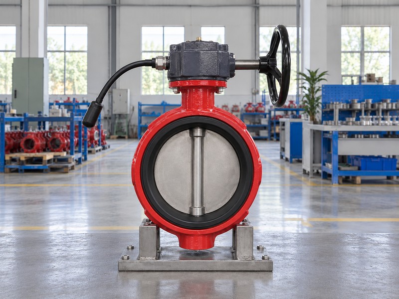
Link the point with its physical source. Record valve tag, location, switch arrangement, designated input and intended supervisory duty, then retain the applicable configuration documents. A position-related signal cannot by itself describe conditions throughout the water supply network. The static closed-disc illustration depicts an exterior only and provides no evidence of the normal service position, internal switching or an installed panel response.
- Identify the valve location and assigned supervisory role.
- Link the designated contact with its actual input.
- Keep the point definition with accepted system documents.
Key takeaway: A useful point definition connects one identified sensing function with its configured system indication.
| Check | What you should confirm |
|---|---|
| Physical source | Identified valve and sensing arrangement provide the input |
| System point | Assigned input represents the documented device role |
| Event display | Selected configuration determines the reported condition |
2. Which butterfly valve tamper switch state is normal?
The normal state of a butterfly valve tamper switch point begins with the intended normal valve position and selected sensing arrangement. A supply valve designed for supervised-open duty has a different mechanical basis from a model intended to supervise closed. Contact terminology alone cannot establish that basis.
How should mechanical and electrical states be recorded?
Keep both descriptions in the schedule. The Victaulic Series 705 information identifies an open-supervised model that cannot supervise closed, demonstrating why the actual product matters. Its switch diagram then defines contact behavior for that arrangement. Record the expected panel indication separately, without assuming that ‘normally closed’ means the valve is closed or that changing leads converts the supervised mechanical position.
- Record the actual intended normal valve position.
- Use the selected diagram for contact-state descriptions.
- Retain the expected input and panel conditions separately.
Key takeaway: Define normal at the valve, contact and panel levels before classifying a reported change.
| Check | What you should confirm |
|---|---|
| Valve state | Project duty and selected model define normal position |
| Contact state | Product diagram defines the electrical reference condition |
| Panel state | Accepted configuration defines the expected indication |

3. Is a butterfly valve tamper switch a waterflow alarm?
A butterfly valve tamper switch monitors its defined valve-position relationship rather than water moving through the piping. A separate waterflow device and assigned input serve the project’s waterflow-detection function. Keep these sources distinct even when their points share the same riser, room or panel.
Why must the device source remain visible?
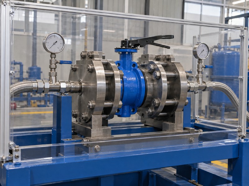
Describe what each input detects. A valve-position event can indicate departure from the intended position, while the waterflow point reports the condition defined by its own device and system configuration. A normal valve point does not prove available supply, an unobstructed waterway or actual flow. The hydraulic fixture illustration concerns another evidence category; it supplies no waterflow alarm result, pressure reading or demonstrated supervisory response.
- Name position supervision and waterflow as separate functions.
- Keep each device linked with its assigned input.
- Avoid using a normal valve point as proof of supply.
Key takeaway: Classify an event from its identified device and configured function rather than its location near a water pipe.
| Check | What you should confirm |
|---|---|
| Valve position | Switch reports its monitored mechanical relationship |
| Waterflow | Dedicated device detects its specified flow condition |
| Hydraulic evidence | Records address their stated pressure, flow or leakage scope |
4. Which faults concern a butterfly valve tamper switch?
Circuit trouble associated with a butterfly valve tamper switch is a different condition from the intended position-related event. The selected input design determines which electrical faults it can detect and how they appear. A familiar valve label cannot establish that the disc actually moved when trouble is reported.
What should the fault definitions explain?
Read the selected input and panel documentation. Contact actuation, a broken conductor and loss of module communication describe different situations, even if one point description appears beside them in a log. The actual circuit topology and programming control their detection and displayed classification. Record the supported fault conditions rather than declaring that every open circuit, short circuit or contact change produces the same event across all systems.
- Separate intended contact actuation from detected circuit faults.
- Record supported fault indications from selected equipment information.
- Keep module communication faults distinct from valve-position assumptions.
Key takeaway: Trouble describes a detected equipment or circuit condition whose meaning follows the selected system.
| Check | What you should confirm |
|---|---|
| Position event | Configured input receives the designated switch condition |
| Input fault | Selected equipment detects a supported circuit abnormality |
| Communication | Panel reports module-link conditions as its design specifies |
5. Where does a butterfly valve tamper switch input belong?
A butterfly valve tamper switch contact belongs on the compatible monitored input specified for its supervisory duty. In an addressable system, a monitoring module can connect that contact function with the panel. The module’s monitored input and its panel communication circuit perform separate roles.
How does the module boundary affect event meaning?
Identify the actual module and accepted configuration. The Potter PAD100-MIM manual distinguishes its compatible SLC connection from the separate monitored input used for dry contacts. Ordinary valve contacts must not connect directly across the SLC. Input compatibility, supervised circuit arrangement and panel programming govern the point’s behavior, so a generic contact symbol cannot define every event or fault response.
- Identify compatible panel and module equipment.
- Separate the monitored input or IDC from the SLC.
- Keep selected circuit and programming information with the point schedule.
Key takeaway: An addressable point needs the module, monitored circuit and panel configuration identified as separate parts.
| Check | What you should confirm |
|---|---|
| Valve contact | Provides its assigned dry-contact condition |
| Monitored input | Receives contacts through the specified circuit arrangement |
| Compatible SLC | Connects the addressable module with its permitted panel |

6. Which butterfly valve tamper switch output is auxiliary?
An auxiliary contact in a butterfly valve tamper switch assembly can have a different permitted duty from the designated supervisory contact. Matching SPDT contact symbols do not make those outputs interchangeable. Identify each circuit from the selected manufacturer’s information before assigning local or system functions.
Can a spare contact replace the supervisory output?
Preserve the manufacturer’s assigned roles. The Victaulic installation instructions designate S1 for the fire alarm supervisory connection and S2 for auxiliary devices, with restrictions stated for that product. Other assemblies need their own circuit-duty review. Record any auxiliary indication or equipment function separately from the fire panel point, including its response owner and the evidence required for acceptance.
- Identify designated supervisory and auxiliary circuit duties.
- Retain manufacturer restrictions on permitted connections.
- Assign auxiliary functions their own descriptions and owners.
Key takeaway: Preserve each contact’s documented duty instead of treating an unused output as a universal spare.
| Check | What you should confirm |
|---|---|
| Supervisory output | Selected product permits its fire panel input duty |
| Auxiliary output | Selected product permits its separate assigned function |
| Operational record | Each function has an identified purpose and response owner |
7. How should a butterfly valve tamper switch point be named?
Name a butterfly valve tamper switch point so staff can locate the valve and recognize its assigned function. Use the project tag and a physical location that remains meaningful after handover. A label such as valve alarm can blur device identity, event classification and the area affected.
Which details make event text usable?
Link the screen description with the installed tag. A description can identify a riser, valve tag and supervisory role without implying waterflow detection or automatic shutoff. Keep point address, area served and device identity in the supporting schedule when display space is limited. The static installation illustration carries no readable location labels and cannot validate the mapping between a real valve and a programmed point.
- Use the actual valve tag and recognizable location.
- Keep device role distinct from the displayed event class.
- Retain supporting address and area information in the schedule.
Key takeaway: Point text should identify the source clearly while the schedule preserves its complete functional definition.
| Check | What you should confirm |
|---|---|
| Identity | Point maps to an installed valve tag |
| Location | Description guides staff to the correct valve |
| Function | Supporting schedule states position supervision and assigned event |

8. What actions follow a butterfly valve tamper switch event?
The response to a butterfly valve tamper switch event should follow the approved cause-and-effect schedule and site responsibilities. Define who receives the information, who evaluates its source and who can authorize physical work. The contact itself does not decide notification routes or command automatic valve movement.
What should the response schedule distinguish?
Assign actions by event class. Position-related supervisory information, detected circuit trouble and a separately configured waterflow alarm can require different escalation paths under the project’s accepted arrangements. Acknowledging an indication does not change the physical valve position or demonstrate restored protection. Keep any authorized testing, valve movement or corrective work within the selected instructions and project controls rather than treating a generic event label as permission.
- Assign notification and evaluation responsibilities by event class.
- Separate acknowledgement from correction and verified restoration.
- Keep physical action subject to the authorized project procedure.
Key takeaway: A response schedule connects the classified event with accountable actions and defined authorization.
| Check | What you should confirm |
|---|---|
| Notification | Accepted schedule defines recipients and escalation |
| Evaluation | Responsible team checks the identified event source |
| Physical work | Authorized personnel follow selected instructions and controls |

9. What records verify a butterfly valve tamper switch event?
Acceptance records for a butterfly valve tamper switch point should correlate the identified device with its actual programmed indication. Record the required normal, changed and restored conditions under the authorized verification procedure. Keep circuit-fault observations separate from valve-position observations so their event meanings remain traceable.
How should verification evidence be described?
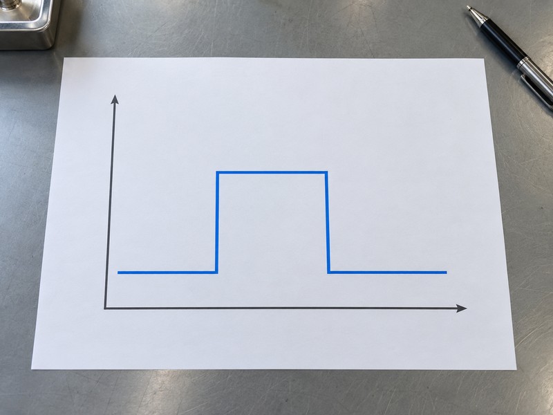
Record observations at their source. The responsible team needs the valve identity, selected input, actual event class and displayed text, with results assessed against the approved project requirements. The abstract sequence chart shows initial, changed and restored states only, without contact polarity, voltage, valve angle, elapsed time or measured results. A record of normal restoration must state what was verified rather than imply proof of water supply or seat sealing.
- Link observations with the valve tag and selected input.
- Record actual event class, displayed text and restoration.
- Keep required circuit-fault evidence under its own scope.
Key takeaway: Verify event meaning through accepted device-to-point records rather than a conceptual chart or assumed contact behavior.
| Check | What you should confirm |
|---|---|
| Source | Observed condition belongs to the identified device |
| Display | Recorded event class and text match accepted mapping |
| Restoration | Required states return as specified and are documented |
10. Who owns a butterfly valve tamper switch response?
Give each butterfly valve tamper switch point a clear handover chain from product information through panel configuration to operational response. The valve supplier, alarm team and facility team contribute different information. A shared event log cannot replace an agreed owner for unresolved classifications or reported defects.
Which responsibilities should survive handover?
Retain named roles with the records. Product documentation identifies the permitted sensing and contact duties, the alarm team records accepted input behavior and programming, and the facility team follows its agreed response arrangements. Keep replacement identities and approved changes linked with that same point history. RUITO can review valve application and assembly information; the responsible project teams must define and verify panel behavior and site response ownership.
- Retain product and replacement identities with the point history.
- Assign accepted programming and event records to the alarm team.
- Document facility response ownership and change-review responsibilities.
Key takeaway: Handover should leave an identifiable event source, accepted classification and accountable response owner.
| Check | What you should confirm |
|---|---|
| Product information | Supplied documents define permitted sensing and contact duties |
| Alarm configuration | Responsible team retains accepted input and event mapping |
| Site operation | Assigned owner follows documented response and escalation |
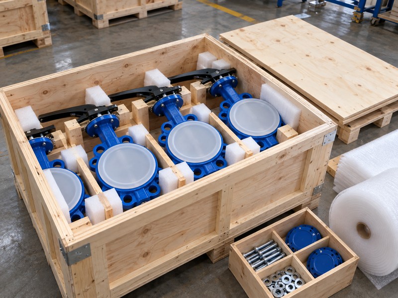
Send RUITO the valve identification, intended normal position and available assembly documents when the product’s sensing or contact duties need clarification. We can review the supplied application information and identify outstanding product questions. Contact us while the responsible project teams retain the accepted panel configuration and event-response records.
FAQ
Q1: Does a valve supervisory event mean water is flowing?
No. Valve-position supervision and waterflow detection have separate device roles and assigned inputs.
Q2: Does circuit trouble prove that the valve moved?
No. Read the actual fault classification using selected input and panel documents; the reported condition may concern circuitry or communication.
Q3: Can an auxiliary contact replace the designated supervisory output?
Only where the selected product and approved project arrangement permit it. Matching contact symbols do not establish interchangeable duties.
Q4: Does acknowledging an event restore the valve?
No. Acknowledgement does not change physical valve position or verify restored protection. Follow the accepted response and restoration arrangements.
Q5: What should the handover point schedule retain?
Keep valve tag, location, device role, selected input, intended normal state, event classification, displayed text and response owner.