
Fix drawing mistakes by matching each required fact with the correct controlled document and applicable revision. A double offset butterfly valve drawing can show an external arrangement, internal section or component detail, depending on its purpose. Read it within the complete document chain before accepting fit, geometry, duty or supplied configuration.
Two files can show the same nominal valve size while describing different body styles, seat arrangements or operator mountings. Their similar appearance can conceal a revision mismatch that reaches purchasing or inspection. Request the document index, identify the applicable configuration and check the references before treating either file as authority for the supplied valve.
1. What identifies a double offset butterfly valve drawing?
Identify a double offset butterfly valve drawing through its drawing number, revision, model or configuration reference and stated purpose. Nominal diameter alone cannot distinguish body, seat and operator variants. Check document status and the supply reference before using an image or catalogue page as a project drawing.
Which identifiers should agree across the package?
Read the drawing identity. Match the title block and configuration reference with the accepted order, data sheet and supplied valve identification where available. RUITO’s separate wafer and double-flanged double-offset descriptions do not establish one combined construction or drawing set. A generic exterior image cannot verify internal geometry, model identity, revision or availability for the proposed configuration.
- Record drawing number, revision and configuration reference.
- Identify document purpose and applicable supply scope.
- Match the drawing identity with accepted project records.
Key takeaway: Link the identified drawing with its accepted configuration and supply scope.
| Check | What you should confirm |
|---|---|
| Document | Number and revision identify the actual file |
| Configuration | Model and component references define the reviewed construction |
| Application | Order or project reference establishes intended use |
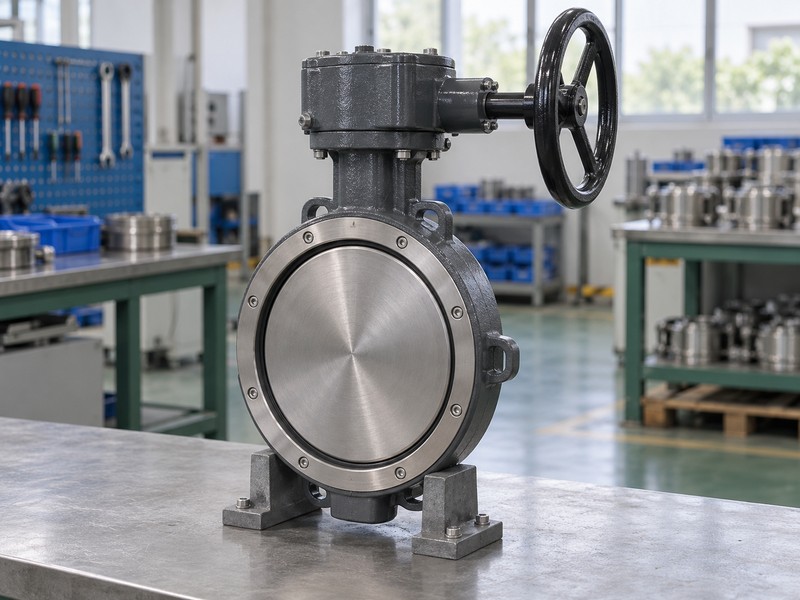
2. What does a double offset butterfly valve drawing GA show?
A general arrangement, or GA, within a double offset butterfly valve drawing package usually addresses the external assembly and interfaces identified on that sheet. Read the actual views, dimensions and notes rather than assuming every internal detail is included. A complete exterior outline cannot by itself establish seat construction or offset dimensions.
Which facts need another document type?
Separate external arrangement from internal definition. The Bray McCannalok technical manual distinguishes body-style dimensions, component information and performance tables for its identified family. Use the selected GA for its stated external scope, then follow references to sections, parts definitions and duty records. Wafer, lug and double-flanged versions require their own applicable interfaces; one outline cannot establish another construction’s dimensions.
- Read each GA view and its stated external scope.
- Follow references for internal components and duty information.
- Keep body-style variants tied to their actual drawings.
Key takeaway: Use each document for its defined facts and follow references for missing details.
| Check | What you should confirm |
|---|---|
| GA | Shows the external arrangement and stated interfaces |
| Section | Defines identified internal relationships and construction |
| Supporting data | Establishes component and performance details within its scope |
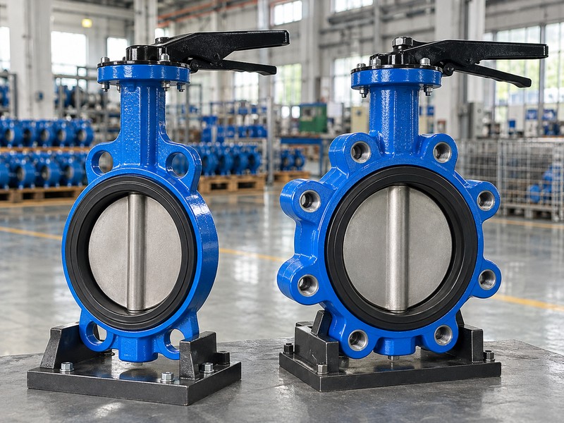
3. What section supports a double offset butterfly valve drawing?
A section in a double offset butterfly valve drawing package must identify the shaft rotation axis and the sealing references needed to read the two offsets. View direction and datum definitions determine how dimensions should be interpreted. The offsets describe designed displacements, not a bent shaft or separate rotation axes.
Which references make offset dimensions readable?
Locate the dimension references. The Keystone K-LOK technical sheet illustrates axis relationships for its identified design. Read displacement from the seat plane and the bore or seat centerline using the selected manufacturer’s coordinate and naming conventions. A diagram without controlled dimension references, tolerances or configuration identity cannot supply missing manufacturing dimensions, and an exterior photograph cannot establish them.
- Identify rotation axis, sealing plane and centerline references.
- Read view direction and selected datum conventions.
- Request missing controlled dimensions instead of estimating from pictures.
Key takeaway: Read offset dimensions through controlled references and the applicable section.
| Check | What you should confirm |
|---|---|
| Axis | Section identifies the designed shaft rotation reference |
| Offsets | Dimensions relate the axis to stated sealing references |
| Control | Required dimension and tolerance definitions remain traceable |
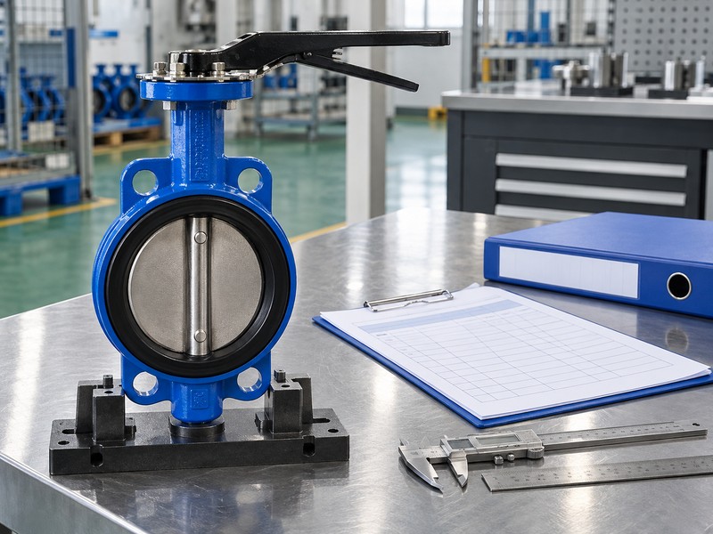
4. What dimensions govern a double offset butterfly valve drawing?
Dimensional facts in a double offset butterfly valve drawing need explicit callouts, applicable notes and the selected interface definition. Separate face-to-face length, flange construction and bolting from the disc’s moving envelope. A static body outline cannot establish every clearance needed by the open disc or adjacent components.
How should readers handle incomplete or unscaled views?
Read the stated dimensions. Identify units, referenced standards where given, view applicability and any separate swept-envelope detail for the selected construction. Do not derive manufacturing or installation values from an AI image, screenshot or resized catalogue illustration. The static layout supplies no accepted fit result; unresolved flange, facing, bolting, lining or disc-clearance information needs the appropriate controlled detail rather than a proportional estimate.
- Read units, dimension notes and applicable interface references.
- Separate body dimensions from the full disc envelope.
- Request missing details without scaling illustrative pictures.
Key takeaway: Use stated dimensions and controlled envelope details for the actual construction.
| Check | What you should confirm |
|---|---|
| Static dimensions | Selected callouts define the external mating geometry |
| Moving envelope | Applicable detail defines required disc movement space |
| Missing data | Manufacturer detail resolves the unresolved interface fact |
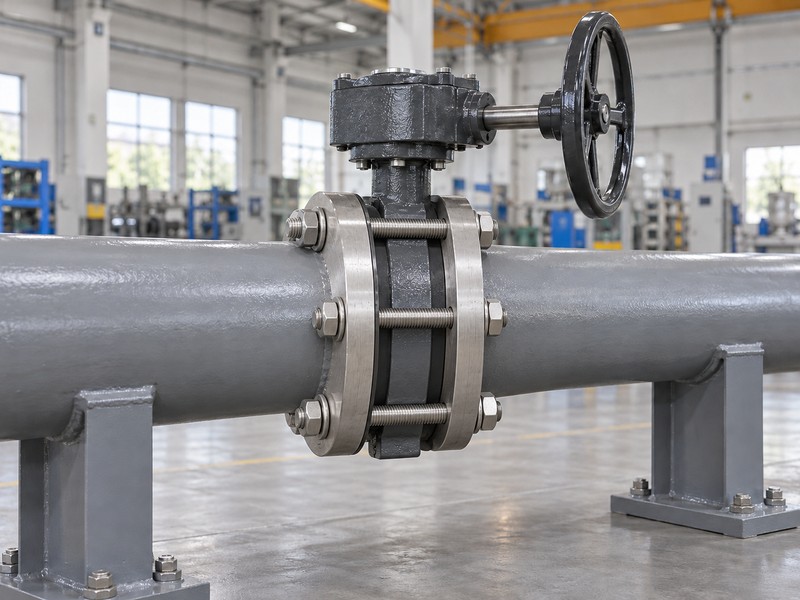
5. What drive details need a double offset butterfly valve drawing?
A double offset butterfly valve drawing package should identify which sheet defines the stem drive and operator attachment. Mounting-face dimensions and drive geometry answer different questions. Shaft profile, engagement, orientation, bracket arrangement and permitted loads may require a separate detail or selected operator document.
Which operator facts cannot come from an outline alone?
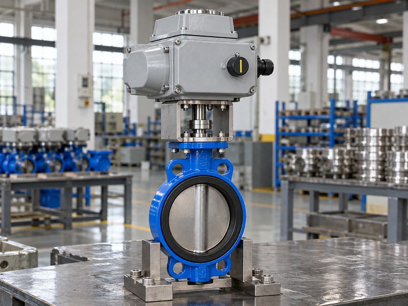
Follow the drive references. Match the shaft and mounting detail with the actual valve and operator versions, including the selected travel and indication definitions. Request missing coupling or engagement information when a GA shows only the outer enclosure. A generic electric-operator illustration proves no shaft fit, torque capacity or internal valve geometry, while a matching mounting pattern cannot establish the complete operating package.
- Separate mounting-face data from actual drive geometry.
- Match valve, coupling, bracket and operator references.
- Retain selected travel, indication and permitted-load documents.
Key takeaway: Follow referenced details and operating records for the complete drive definition.
| Check | What you should confirm |
|---|---|
| Mounting | Selected detail defines attachment geometry and bracket arrangement |
| Drive | Actual profile, engagement and orientation are identified |
| Operation | Separate records define travel and permissible operating loads |
6. What parts match a double offset butterfly valve drawing?
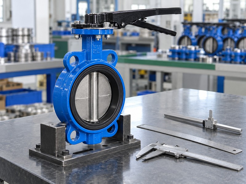
Assembly views and parts lists supporting a double offset butterfly valve drawing should connect item callouts with the actual component definition. Seat, retainer, gasket, fasteners, shaft and support parts need applicable identities. An exploded view can locate components without providing all material, tolerance or replacement-compatibility information.
How should assembly callouts connect with repair records?
Match callouts with the parts definition. The Bray McCannalok maintenance manual distinguishes component arrangements and matched replacement relationships for its identified constructions. Follow the selected assembly’s parts list and maintenance instructions rather than assuming similar-looking retainers or seats are interchangeable. Keep seat-retainer hardware distinct from pipe-flange bolting, with materials and revision references read from the appropriate controlled records.
- Link assembly item callouts with applicable parts records.
- Check selected seat and retainer versions explicitly.
- Use maintenance information for permitted replacement relationships.
Key takeaway: Link parts callouts with the correct component and repair definitions.
| Check | What you should confirm |
|---|---|
| Assembly view | Item references locate components in the selected construction |
| Parts definition | Applicable identity and material records describe those items |
| Repair information | Selected instructions define permitted replacement relationships |
7. What duty backs a double offset butterfly valve drawing?
A double offset butterfly valve drawing can reference operating limits without containing every supporting performance record. Identify where the selected configuration’s media, pressure-temperature, directional differential and torque information resides. An arrow or pressure-class note cannot replace the complete duty definition for the supplied assembly.
Which cross-references establish the operating basis?
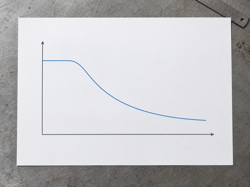
Connect geometry with selected duty records. Retain the applicable data sheet, pressure-temperature information, direction definitions and operator-sizing basis under the same configuration identity. Read preferred orientation separately from permitted forward and reverse differential or throttling restrictions. The conceptual chart shows temperature increasing rightward and allowable pressure upward, but it supplies no actual rating drawing, material curve, operating point or universal derating rule.
- Identify separate selected pressure-temperature and media records.
- Retain actual directional differential and orientation definitions.
- Link torque and operator data with the same assembly identity.
Key takeaway: Confirm operating capability through the referenced configuration and duty data.
| Check | What you should confirm |
|---|---|
| Limits | Selected performance documents define the permitted duty |
| Direction | Applicable records distinguish orientation and differential limits |
| Operator | Sizing information matches the selected valve and service |
8. What records verify a double offset butterfly valve drawing?
Inspection records associated with a double offset butterfly valve drawing should identify the supplied valve and the applicable drawing requirements. A drawing states what the selected design requires; an inspection result records what was checked. Keep dimensional, material, functional and pressure evidence within their separately defined scopes.
How should drawing requirements connect with acceptance results?
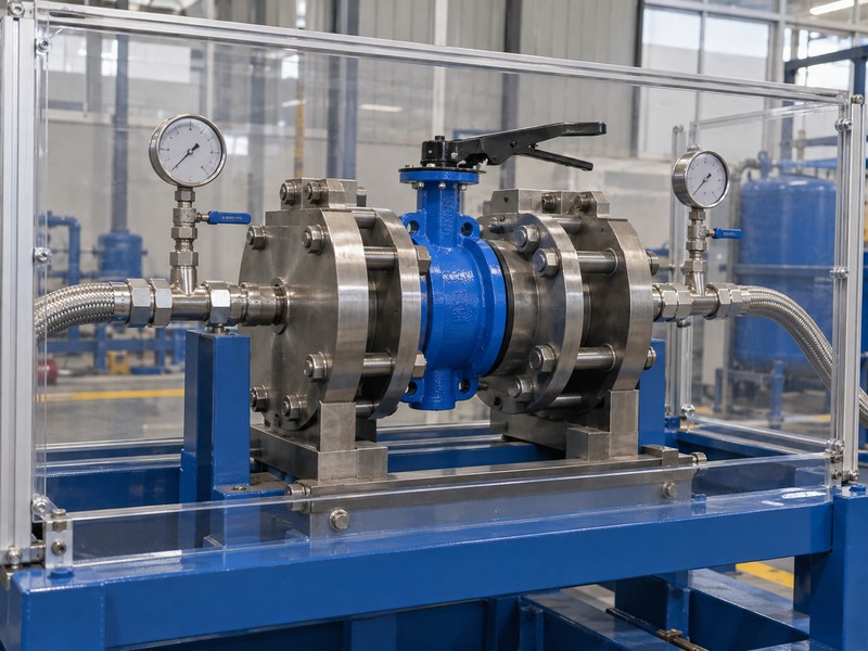
Trace the requirement to its evidence. Match actual product identity, drawing revision and relevant inspection definition with the agreed results, including accepted deviations where applicable. A dimensional report cannot prove seat leakage or actuator performance, and a pressure report cannot establish every critical interface dimension. The generic hydraulic fixture image provides no actual reading, test result or confirmation that the supplied drawing was followed.
- Match supplied identity and applicable drawing revision.
- Link required characteristics with their actual inspection records.
- Keep deviations and separate test scopes visible at acceptance.
Key takeaway: Accept the supplied assembly through identified requirements and matching inspection results.
| Check | What you should confirm |
|---|---|
| Requirement | Applicable drawing and inspection definition identify the check |
| Result | Recorded evidence identifies the actual supplied item |
| Acceptance | Agreed criteria and accepted deviations remain traceable |
9. What revision governs a double offset butterfly valve drawing?
The governing revision of a double offset butterfly valve drawing is the version applicable to the accepted configuration and supply scope. The newest online file is not automatically the released drawing for an existing order. Check status, revision history and accepted changes across the document package.
How should readers resolve conflicting versions?
Check the applicable release chain. Retain the accepted drawing list, change record and affected parts or instruction revisions, then identify which documents remain valid for the supplied assembly. Resolve a mismatch through the responsible document owner instead of selecting whichever sheet looks newer. Keep replaced versions identifiable as superseded for that scope, with shipment or handover records linked to the accepted configuration.
- Identify the revision released for the actual supply.
- Review accepted changes across drawings, parts and instructions.
- Resolve version conflicts through the responsible document owner.
Key takeaway: Use the applicable accepted revision and its connected configuration records.
| Check | What you should confirm |
|---|---|
| Applicability | Accepted document list identifies the required revision |
| Change | Revision record describes affected configuration information |
| Handover | Supplied identity and records match the accepted release chain |
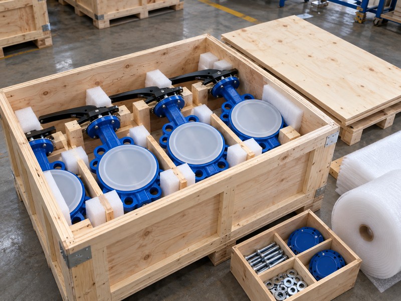
10. What CAD supports a double offset butterfly valve drawing?
Request CAD associated with a double offset butterfly valve drawing by actual configuration, revision and intended use. An external coordination model may answer envelope questions while leaving internal design or manufacturing detail outside its scope. File format alone cannot establish accuracy, completeness, permission to modify or release authority.
What should the actual drawing request specify?
Request an identified deliverable. State the valve and operator identity, required interfaces, application purpose and preferred format, then confirm which files can be supplied under the applicable authorization. Ask which controlled document governs when a CAD model and a formally issued drawing differ. RUITO can review the application and document request, but a general product category or rendered picture cannot establish a ready-to-download model for an unconfirmed configuration.
- Identify configuration, revision and the intended CAD use.
- Confirm available formats and the permitted delivery scope.
- Retain the governing drawing and accepted model relationship.
Key takeaway: Request an identified drawing or model and confirm its applicable scope.
| Check | What you should confirm |
|---|---|
| Request | Actual configuration and required interfaces are identified |
| Deliverable | Supplier confirms format, revision and authorized scope |
| Authority | Accepted records define which document governs the review |
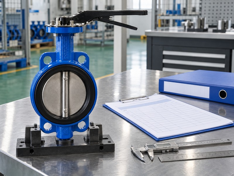
Send RUITO the valve and operator identity, existing drawing number and revision, service requirements and the detail or CAD purpose you need resolved. We can review the supplied application information and confirm the proposed document scope. Contact us before treating an unidentified picture or separate product descriptions as a controlled drawing package.
FAQ
Q1: Can a GA prove the two offset dimensions?
Only if it explicitly defines them with applicable references. Otherwise request the selected controlled section or dimensioned detail.
Q2: Can I measure missing dimensions from an AI valve image?
No. Use stated dimensions and controlled details for the actual model and revision rather than picture proportions.
Q3: Does the newest catalogue drawing govern an existing order?
Not automatically. Confirm the revision applicable to the accepted configuration, released document list and approved changes.
Q4: Does an assembly drawing establish every replacement part?
No. Connect its callouts with the applicable parts definition and maintenance instructions for the selected construction.
Q5: Does a CAD format guarantee an approved manufacturing model?
No. Confirm configuration, revision, intended purpose, authorized scope and the governing relationship with the formally issued drawing.