
Correct mounting starts with an aligned, supported drive between the valve shaft and actuator. When you specify a butterfly valve with double acting actuator, check the shaft connection, bracket, mounting faces, fasteners, and full installation envelope together. A package can share a nominal mounting pattern and still bind because its coupling or support is wrong. Use the approved assembly drawing to close those interfaces before a factory sample becomes the production configuration.
1. How should a butterfly valve with double acting actuator fit?
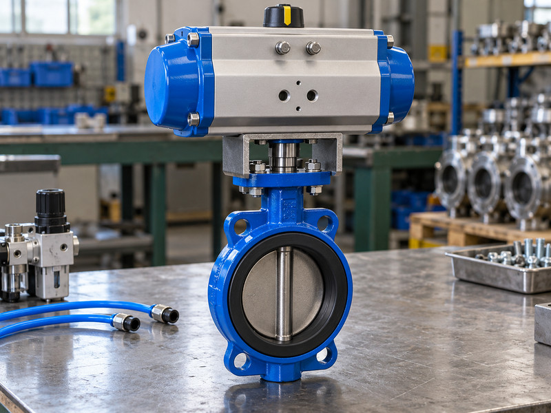
An acceptable arrangement transmits torque through the intended drive while supporting the actuator and maintaining alignment. Your butterfly valve with double acting actuator needs more than matching bolt holes. Its coupling engagement, mounting faces, bracket stiffness, travel limits, and access must suit the actual operating load and installation.
Which drawing should you approve?
It should show the valve, actuator orientation, bracket, coupling, fasteners, and any mounted accessories. Check that component descriptions correspond to the quotation and bill of materials. A drawing of a bare valve cannot establish clearance for an actuator end cap or a top-mounted switch box. If the supplier uses a standard bracket, request the dimensions and load basis relevant to your assembly.
- Identify the actual valve and actuator combination.
- Include mounting hardware and accessories in the envelope.
- Keep the approved revision with the purchase record.
- Record the approved revision so a later substitute does not change installation fit without review.
| Drawing item | Required detail | Purpose |
|---|---|---|
| Drive connection | Shaft form and coupling engagement | Transmit torque correctly |
| Support | Bracket and fastener arrangement | Maintain alignment under load |
| Envelope | Actuator and accessory dimensions | Preserve installation and service access |
Key takeaway: Approve the assembly you will install rather than two compatible-looking component drawings.
2. What does the mounting pad tell you?
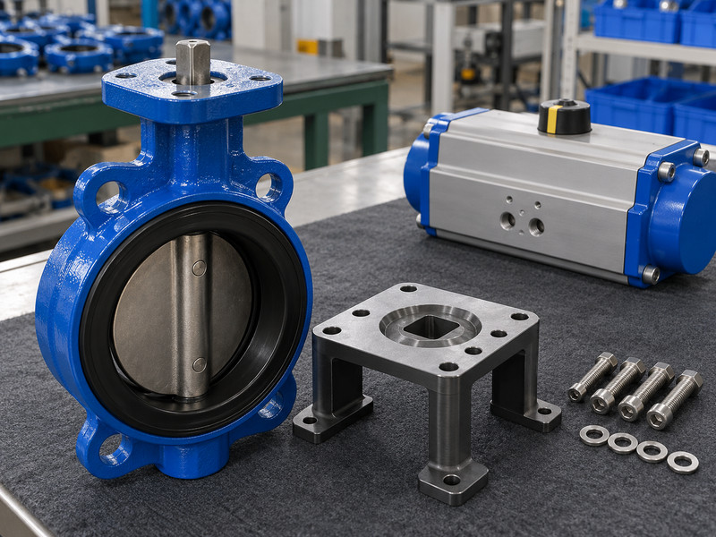
The mounting pad identifies part of the actuator connection, including its relevant dimensional arrangement. A butterfly valve with double acting actuator still needs a separate torque and drive-strength review. A mounting reference alone does not prove that the selected actuator fits the actual shaft or suits the service.
Which interface dimensions should you compare?
Check bolt pattern, pilot or locating features where used, shaft position, shaft projection, and the coupling’s internal form. Confirm how the assembly locates the actuator relative to the shaft. A plate drilled with convenient holes can conceal poor location or excessive clearance. Where an ISO 5211 interface is specified, verify the applicable dimensions and the complete drive arrangement rather than treating the standard’s name as approval of the valve torque, material, or process duty.
- Check locating features as well as mounting holes.
- Confirm shaft projection and drive orientation.
- Review the complete interface against the selected hardware.
| Interface feature | Comparison | Failure it can prevent |
|---|---|---|
| Hole pattern | Valve, bracket, and actuator drawing | Incorrect assembly fit |
| Shaft location | Coaxial drive geometry | Binding and side loading |
| Shaft projection | Available coupling engagement | Partial engagement or bottoming |
Key takeaway: A recognized mounting interface helps dimensional review but does not replace it.
3. How should you check the shaft coupling?
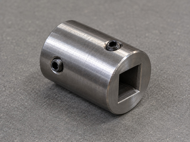
Check coupling fit, engagement, material, retention, and allowable torque against the approved drive arrangement. In a butterfly valve with double acting actuator, a coupling that engages only a short length can concentrate load even when the actuator moves normally without process pressure. Inspect the connection before judging the assembly by cycling alone.
What should you inspect during assembly?
Confirm that the coupling engages the specified shaft shape without forcing, bottoming, or relying on unintended contact. Check any keys, retaining features, and permitted clearances according to the drawing. Avoid modifying a coupling at the assembly bench to make it fit without engineering approval. If a replacement uses a different coupling design, review its torque capacity and engagement dimensions.
- Verify the engagement length and actual shaft form.
- Check retention and any specified key arrangement.
- Approve coupling changes before fitting the actuator.
- Retain enough information to order the correct part later rather than describing it only as a “standard adaptor.”
| Coupling detail | Acceptance basis | Inspection method |
|---|---|---|
| Internal form | Matches the specified shaft | Drawing and dimensional check |
| Engagement | Meets the approved arrangement | Assembly measurement |
| Torque capacity | Covers applicable drive output | Documented engineering review |
Key takeaway: Correct coupling engagement is a mechanical requirement even when an unloaded cycle looks satisfactory.
4. What should the bracket support?
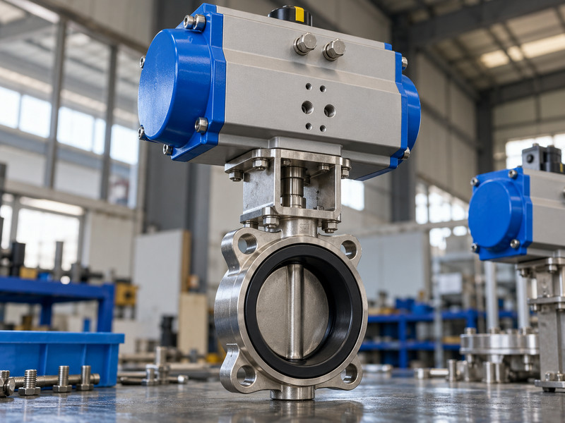
The bracket should support the actuator and transmit the applicable reaction loads while preserving drive alignment. A butterfly valve with double acting actuator can suffer from a bracket that distorts when bolts are tightened or when the drive develops torque. Review the bracket as a loaded component.
How do you evaluate a substitute bracket?
Review material, geometry, mounting-face alignment, fasteners, support spacing, and the loads used for selection. Include environmental exposure and any accessory or manual-override weight that changes the assembly. A taller bracket may improve access but also change stiffness and loads. Mounting bolts should bring correctly made faces together; they should not pull a misaligned actuator into position.
- Confirm the bracket’s geometry and material.
- Review reaction loads and mounting-face alignment.
- Reassess extensions or orientation changes before assembly.
- If insulation, shaft extensions, or an unusual orientation are required, obtain an approved arrangement for those conditions.
| Bracket change | Possible effect | Required review |
|---|---|---|
| Greater height | Different stiffness and loading | Mechanical design and alignment |
| New material | Different corrosion or strength behaviour | Material suitability |
| Added accessories | Additional mass and envelope | Support and service clearance |
Key takeaway: Freeze the bracket design with the actuator selection so installation fit and load assumptions remain connected.
5. How do you protect disc clearance at the pipe connection?
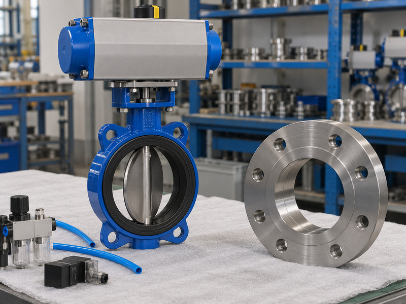
Protect disc clearance by comparing the full disc travel envelope with the actual mating bores and nearby components. A butterfly valve with double acting actuator can strike a flange, lining, or adjacent fitting even when its actuator mounting is correct. Check the pipe interface before energizing the assembly.
Which installation details change the available space?
Confirm pipe bore, flange bore, lining thickness, face-to-face length, and the position of nearby equipment. Follow the valve’s installation procedure for disc position during fitting and tightening. For resilient-seated designs, check whether the seat’s flange faces provide the intended seal and whether additional gaskets are permitted. Do not add a gasket by habit.
- Compare the disc envelope with actual mating bores.
- Follow the specified seat and gasket arrangement.
- Verify free travel under the permitted installation procedure.
- For flanged butterfly valves, use the approved model’s face length and drilling rather than assuming a wafer valve’s dimensions apply.
| Installation feature | Required information | Risk |
|---|---|---|
| Flange or pipe bore | Actual internal dimensions | Disc interference |
| Lining or gasket | Approved arrangement and thickness | Reduced clearance or damaged sealing |
| Nearby fitting | Position relative to valve travel | Contact at an intermediate angle |
Key takeaway: Correct mounting above the valve does not establish clearance inside the pipeline.
6. What should you check about mounting fasteners?
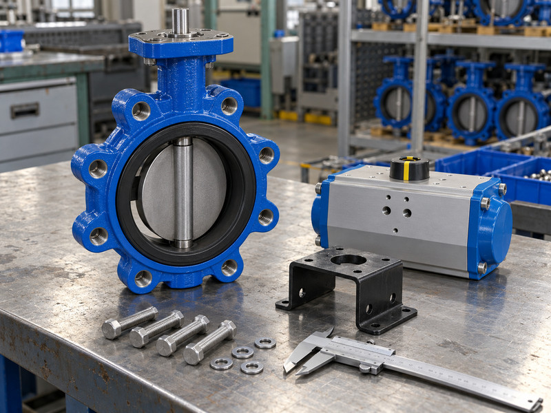
Check fastener grade, dimensions, engagement, tightening method, and connection-specific requirements. A butterfly valve with double acting actuator contains several bolted interfaces, and their requirements differ. Actuator mounting bolts, bracket bolts, and pipe-connection bolts should not be treated as one interchangeable set.
Why does usable thread engagement need review?
Include washers, bracket or flange thickness, available tapped depth, and any interference at the end of the hole. A long bolt can bottom before it clamps correctly, while a short bolt may provide inadequate engagement. Use the specified tightening procedure and tools rather than a general torque borrowed from another assembly. For lug valves, confirm the approved pipe-bolt arrangement and any separately declared end-of-line duty.
- Identify each bolted interface on the drawing.
- Check usable engagement and bottoming clearance.
- Follow the applicable tightening and inspection procedure.
- Threaded lugs alone do not establish that service rating.
| Fastener location | Review focus | Record |
|---|---|---|
| Actuator and bracket | Grade, fit, clamping arrangement | Assembly specification |
| Coupling retention | Intended retention function | Drive drawing |
| Valve and pipe | Connection-specific bolt stack | Installation drawing and procedure |
Key takeaway: Review bolt length against the assembled interface rather than the loose component alone.
7. How much access should you leave around the actuator?
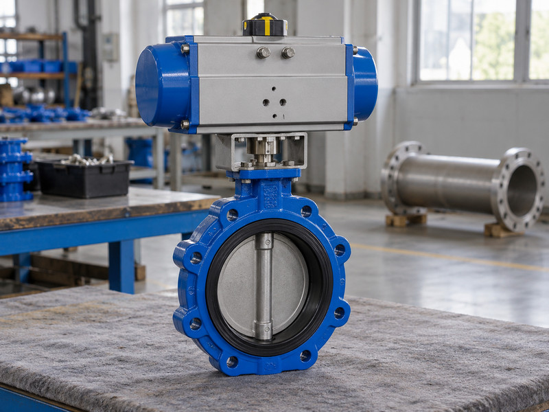
Leave the access needed for installation, adjustment, inspection, and the maintenance activities permitted by the instructions. A butterfly valve with double acting actuator can fit a space yet be difficult to support if its solenoid, switch enclosure, air fittings, or end caps become inaccessible. Include those service needs in layout review.
Which access requirements should appear on the layout?
Check space for connectors, tubing bends, cable glands, fastener tools, and any removable covers. Confirm lifting and support arrangements using approved lifting points; do not assume an actuator or air fitting can carry the complete valve assembly. If a manual override is supplied, review its operating envelope and engagement restrictions. Keep the actuator away from avoidable external loads and unsuitable temperature exposure, and obtain the manufacturer’s guidance when the process or surroundings can affect the drive package.
- Include accessories in the installed envelope.
- Identify tools and access needed for approved service work.
- Confirm lifting and support arrangements before delivery.
| Access location | Task to support | Layout check |
|---|---|---|
| Solenoid and fittings | Inspection or replacement | Tool and connector space |
| Feedback enclosure | Setting and service | Cover and cable access |
| Manual override | Permitted operation | Engagement and operating clearance |
Key takeaway: Check service access before a compact layout becomes a permanent maintenance constraint.
8. How do you set and verify travel alignment?
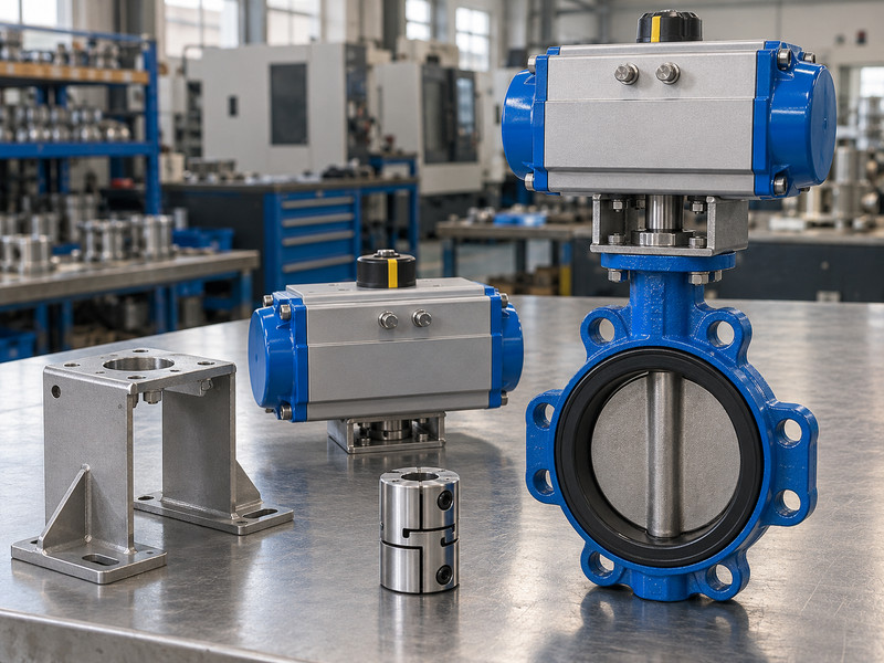
Verify travel alignment by matching actual disc positions with the actuator’s permitted travel and indication. A butterfly valve with double acting actuator should follow the valve and actuator setting procedures together. Do not force extra rotation to make an indicator look correct or to compensate for a misindexed coupling.
What should a final movement check demonstrate?
Confirm coupling indexing, free travel, and the specified open and closed limits. Then verify the local indicator and remote end-position signals against the actual movement. A closed indication does not establish seat leakage acceptance, which needs its own specified test. Record any adjusted stops and use the procedure applicable to the valve design.
- Set the mechanical relationship using the approved procedure.
- Match indication and signals to actual disc travel.
- Keep leakage acceptance separate from position confirmation.
- Excess closing travel or torque can damage a seat even when the actuator itself can continue turning.
| Verification | What it proves | Separate requirement |
|---|---|---|
| Travel check | Defined movement limits | Pressure integrity |
| Feedback check | Correct position signal | Seat leakage acceptance |
| Stop record | Accepted adjustment state | Continued suitability after a change |
Key takeaway: Retain the accepted mechanical settings so later maintenance can restore the same arrangement.
9. What should your assembly release record contain?
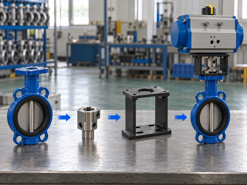
The release record should identify the approved hardware, dimensions, settings, and completed inspections. Your butterfly valve with double acting actuator needs a repeatable assembly definition that purchasing and maintenance can use. A photograph helps identification but cannot replace dimensions or load information.
How do you control later substitutions?
An actuator substitution can change output and clearance; a coupling or bracket substitution can change engagement and alignment. A valve-body change can alter shaft projection or the pipe interface. Require the supplier to present the revised drawing and relevant checks before manufacture. Keep any accepted deviation with the final documents.
- Freeze the assembly bill of materials and drawing revision.
- Retain coupling, bracket, fastener, and travel checks.
- Define the approval process for replacement components.
- This prevents an apparently minor purchasing substitution from returning as a mounting problem when a repeat order reaches the installation crew.
| Release item | Required connection | Used by |
|---|---|---|
| Assembly drawing | Actual delivered configuration | Installation team |
| Mechanical checks | Approved interfaces and limits | Quality and engineering |
| Replacement information | Controlled component identity | Maintenance and procurement |
Key takeaway: Send the valve duty, mounting details, and available space when you contact us. RUITO can identify the interface information needed to review the proposed assembly.
10. What should you ask before fitting an actuator?
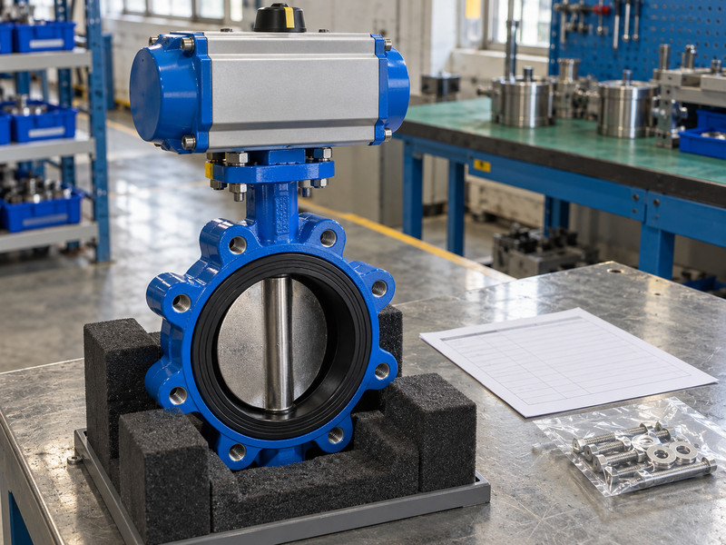
Use these questions when purchasing or modifying a butterfly valve with double acting actuator.
- Q1: Can I use matching mounting holes as proof of compatibility? No. Check shaft form, projection, coupling engagement, allowable torque, support, travel, and the complete installation envelope as well.
- Q2: What’s the best bracket height? Use the height required by the approved geometry and service access. A taller bracket changes stiffness and loading, so it needs a suitable mechanical review.
- Q3: Can I machine a coupling to make it fit? Only through an approved engineering change. Modified geometry or engagement can affect strength, alignment, retention, and the ability to obtain a correct replacement.
- Q4: How do I know if extra flange gaskets are allowed? Read the exact valve’s installation instructions. Some resilient-seat arrangements seal at the flange faces; an added gasket can change compression and clearance.
- Q5: Can I lift the assembly by its actuator? Use only the lifting method and points approved for the complete assembly. An actuator, accessory bracket, or air fitting should not be assumed suitable for that load.