
Integrate a double acting actuator for butterfly valve systems by defining the process duty, available air, command signals, feedback, and failure response together. A valve package can pass its factory movement test and still behave incorrectly when connected to a site’s controls. The missing requirement is often the sequence after a supply failure or restart. Write that sequence before ordering hardware, then assign the factory and site tests needed to verify it.
1. Which double acting actuator for butterfly valve systems fits?
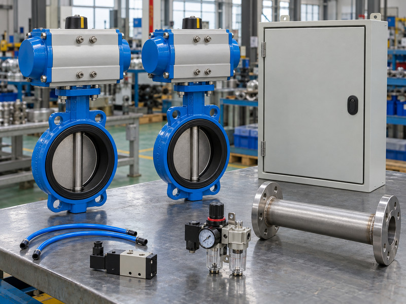
The suitable assembly meets the process, mechanical, pneumatic, electrical, and operating requirements together. Selecting a double acting actuator for butterfly valve systems addresses only one part of the assembly. The system must also establish what the valve should do, what supplies it can depend on, and how operators know its actual state.
How do you assign responsibility for each interface?
The process team defines operating and failure requirements; mechanical engineering confirms valve duty and fit; controls engineering defines commands and signals. The mechanical attachment review can reference ISO 5211 where specified, alongside the actual assembly drawing. Record which checks belong at the factory and which require the installed system. A supplier cannot demonstrate a site’s restart logic on an isolated valve bench unless the relevant controls and acceptance sequence form part of the agreed test arrangement.
- Define process conditions and required valve behaviour.
- Assign owners for air, controls, mounting, and verification.
- Keep factory and site responsibilities visible on one schedule.
| Interface | Required input | Responsible review |
|---|---|---|
| Process | Fluid, differential pressure, failure response | Process and mechanical teams |
| Utilities | Available air and electrical supplies | Site and controls teams |
| Package | Valve, drive, accessories, drawings | Supplier and project engineering |
Key takeaway: Close interface inputs before asking one component supplier to guarantee the complete operating sequence.
2. How should you define the instrument-air boundary?
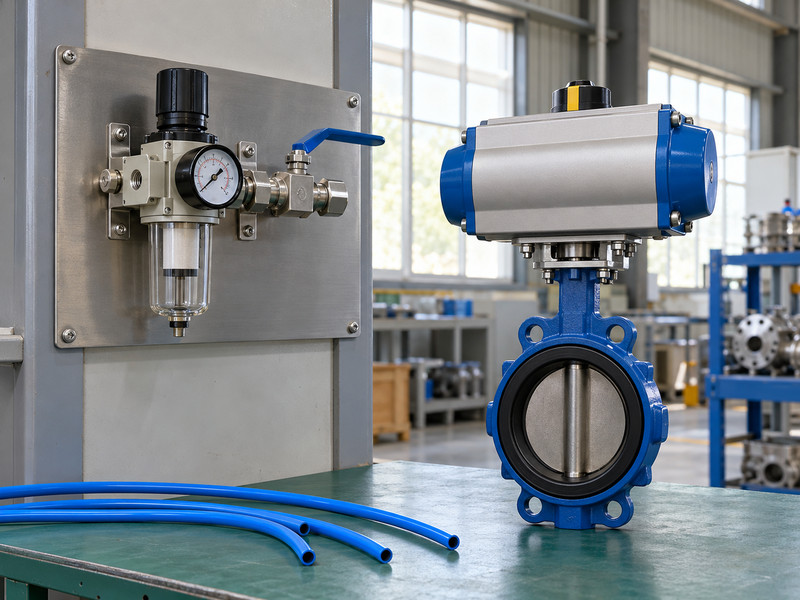
Define the boundary by stating pressure, quality, capacity, connection, and isolation requirements at an agreed location. A double acting actuator for butterfly valve systems needs its minimum dynamic supply condition established at the actuator, after relevant restrictions. An upstream utility specification may need further calculation or measurement.
What should the supplier and site compare?
Record how many actuators can move together, their required travel times, and any low-supply operating case. Review branch piping, regulators, solenoids, tubing, and exhaust paths as part of the air-capacity assessment. Keep normal supply, minimum available pressure, and maximum permitted pressure distinct. If the design uses stored air for a defined response, its capacity, isolation, leakage assumptions, and verification need their own engineering review.
- State minimum and maximum supply conditions separately.
- Include simultaneous demand and the installed air path.
- Define the isolation point used for maintenance and testing.
- Do not infer that arrangement from the presence of a receiver elsewhere on site.
| Boundary detail | Why it is needed | Verification |
|---|---|---|
| Dynamic pressure | Determines available drive output | Calculation or representative measurement |
| Air quality | Affects actuator and accessory operation | Applicable equipment requirements |
| Available capacity | Supports the required sequence | Demand and travel-time review |
Key takeaway: Specify the air condition the package can actually receive during its required movement.
3. Which control commands need definition?
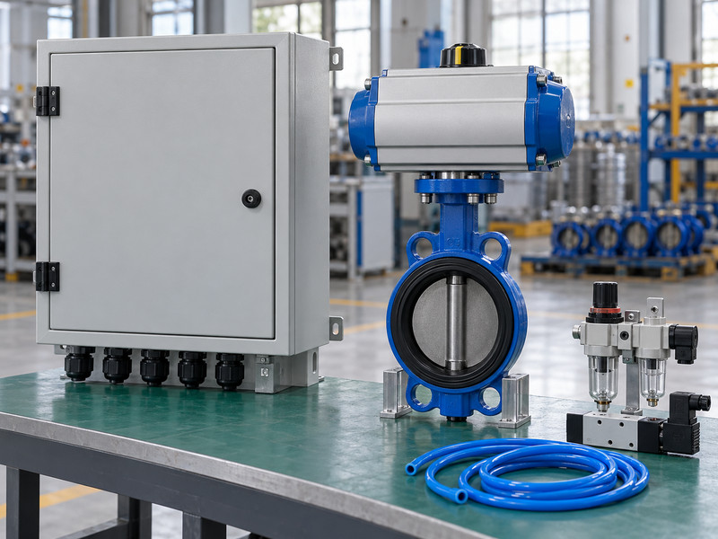
Define normal commands, de-energized states, permissives, manual operation, and restoration behaviour. A double acting actuator for butterfly valve systems can use different directional control arrangements, and those arrangements can respond differently to power loss. “Open/close control” alone leaves several operating decisions unresolved.
What should the control narrative say?
State which command requests opening, which requests closing, and whether the control arrangement maintains or changes state when a signal disappears. Include any local override and how remote operation resumes afterwards. Confirm electrical supply, output type, connectors, and environmental requirements for the selected accessories. The narrative should also identify any condition that inhibits movement.
- Define the commanded and de-energized states.
- Specify local and remote control interaction.
- Write the supply-restoration and restart sequence.
- Keep intended process behaviour separate from the component’s available function so the final design can be checked for a mismatch.
| Control event | Required decision | Test evidence |
|---|---|---|
| Normal command | Intended movement | Command-to-position result |
| Signal or power loss | Required response | Agreed failure sequence |
| Restoration | Conditions for renewed movement | Restart test with the selected controls |
Key takeaway: A written sequence gives the factory and commissioning team a common acceptance target.
4. What should position feedback demonstrate?
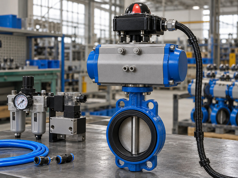
Position feedback should demonstrate the checked mechanical state that the control system needs to observe. For a double acting actuator for butterfly valve systems, actuator travel, valve-disc position, and received electrical feedback should be correlated during acceptance. They are related observations rather than interchangeable proof.
How do you avoid a misleading position signal?
Confirm coupling engagement and indexing, then verify the actual open and closed positions. Check the required signal characteristics and test them at the intended receiving point. If the system uses intermediate-position feedback, define the accuracy and operating requirements separately. A closed signal does not establish the valve’s seat leakage, and a command acknowledgement does not establish movement.
- Match the signal to the actual valve position.
- Verify electrical characteristics at the receiving input.
- Define the response to missing or conflicting feedback.
- Include missing, contradictory, or delayed feedback in the control narrative where the process requires a defined response.
| Observation | What it tells the system | Limitation |
|---|---|---|
| Command acknowledgement | A command was issued or received | Does not prove movement |
| End-position feedback | A checked position was reached | Does not measure leakage |
| Continuous feedback | Reported travel position | Requires its specified calibration and accuracy |
Key takeaway: Accept feedback against the installed mechanical relationship and the required control function.
5. How do you specify loss-of-supply behaviour?
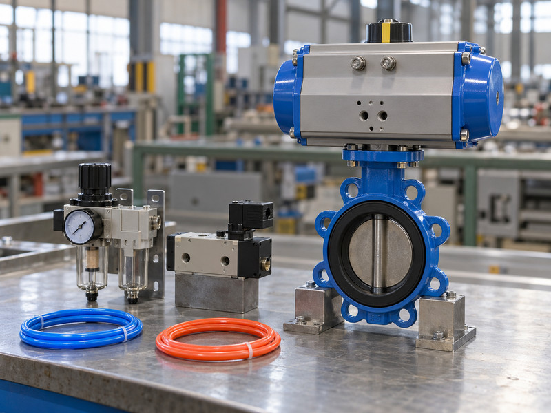
Specify each failure event and the required response of the complete assembly. A standard double acting actuator for butterfly valve systems has no inherent spring-powered return stroke. Loss of electrical power, loss of air, and a damaged working tube can leave different pneumatic conditions and different available energy.
Which assumptions should you challenge during review?
A directional valve may change air routing after power loss while supply air is still available. That does not prove the same response after air loss. Trapped air can leak or be overcome by process loads, so an indefinite maintained position needs an engineered basis. If the process requires a return stroke, review the chosen spring-return or stored-energy solution and its complete verification.
- Separate power-loss, air-loss, and line-failure events.
- State final position, permitted movement, and required time.
- Verify the selected response under defined conditions.
- Keep any declared safety function within the project’s applicable assessment rather than inferring it from a valve’s pneumatic operating principle.
| Failure event | Energy question | Review outcome |
|---|---|---|
| Electrical supply lost | Is usable air still available? | Define directional-control response |
| Air supply lost | What drives or restrains movement? | Verify the engineered arrangement |
| Supply restored | What permits another stroke? | Define restart behaviour |
Key takeaway: The failure response belongs to the system design and test plan, not to the words “double acting.”
6. How should process loads enter the integration review?
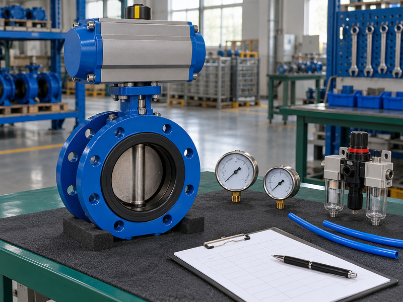
Include normal, maximum, startup, shutdown, and other specified operating cases in the valve and actuator review. A double acting actuator for butterfly valve systems must operate the actual valve against the relevant differential pressure and material conditions. Normal line pressure alone may not describe the worst closing duty.
Which process details affect the package?
Establish maximum closing differential pressure, permitted flow direction, temperature, fluid composition, and any transient or vacuum exposure requiring review. Confirm that the selected valve construction is suitable for the requested isolation or control duty. If the system needs modulation, obtain appropriate flow and operating information for the actual valve. A control signal cannot make an unsuitable valve geometry or seat arrangement acceptable for a demanding process condition.
- Define the maximum applicable differential pressure.
- Review flow direction and any separately rated reverse duty.
- Include temperature, fluid, deposits, and operating pattern.
| Process input | Affects | Required package review |
|---|---|---|
| Differential pressure | Valve torque and shutoff load | Drive sizing and seat acceptance |
| Fluid and temperature | Material and sealing suitability | Configuration-specific limits |
| Operating sequence | Timing and transient exposure | Process and actuation coordination |
Key takeaway: Link the control sequence to the conditions under which the valve must actually move and seal.
7. What access does an integrated installation need?
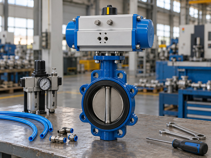
The installation needs access for approved isolation, adjustment, inspection, and component replacement. Choosing a double acting actuator for butterfly valve systems also affects layout through the actuator envelope, tubing, feedback enclosure, and any manual override. Check those items before freezing the skid or pipe arrangement.
What should layout review cover?
Identify the isolation points, tools, removable covers, connectors, and lifting or support arrangements needed for the planned work. Check that tubing and cables do not obstruct other service points or carry unintended loads. For a lug butterfly valve, use the declared connection and end-of-line limitations rather than assuming it can hold any exposed pipe end during maintenance. The maintenance isolation design must remain a separate system responsibility.
- Keep isolation points identifiable and accessible.
- Include accessory covers and tool clearances in the layout.
- Review support and lifting methods for the complete assembly.
| Layout item | Service question | Drawing information |
|---|---|---|
| Actuator envelope | Can approved work be performed? | End-cap and accessory clearances |
| Tubing and cables | Can they be inspected and replaced? | Supported routes and connectors |
| Valve connection | What maintenance loads apply? | Approved connection and isolation arrangement |
Key takeaway: Review the installation for the work your team will need to perform after commissioning.
8. How should factory and site tests work together?
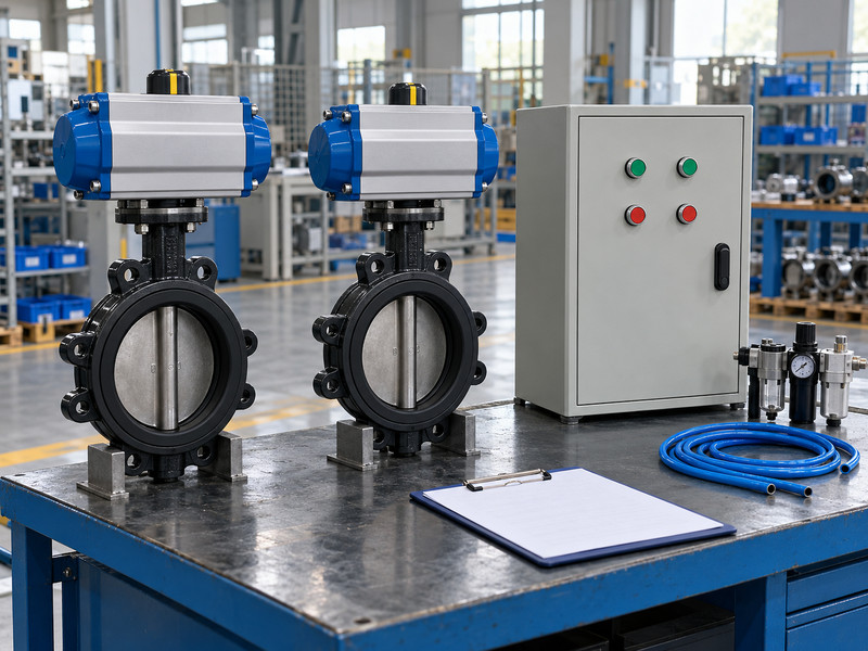
Factory and site tests should cover different parts of one agreed acceptance schedule. A double acting actuator for butterfly valve systems can be checked for assembly movement and accessory function at the factory, while the installed controls, utilities, and process interfaces may require site verification. State those boundaries before testing starts.
What should you avoid leaving to inference?
Identify whether a movement test is unloaded, which air pressure and controls it uses, and which signals are observed. Keep shell integrity and seat closure tests separately identified. At the site, verify installation, command routing, actual feedback, required timing, failure events, and restoration behaviour under the approved procedure. Where a test cannot reproduce the complete process duty, document the limitation and assign the remaining action rather than presenting the partial result as complete acceptance.
- Connect each test to a stated requirement.
- Identify conditions and equipment used for verification.
- Assign the owner of each remaining site action.
| Verification location | Typical scope | Boundary to record |
|---|---|---|
| Component supplier | Individual equipment function | Excludes unprovided system interfaces |
| Assembly factory | Valve, drive, and accessories | Record loading and supply conditions |
| Installation site | Utilities, controls, and installation | Complete the agreed integration checks |
Key takeaway: One test schedule helps prevent both duplicated work and untested interfaces.
9. What information should remain under change control?
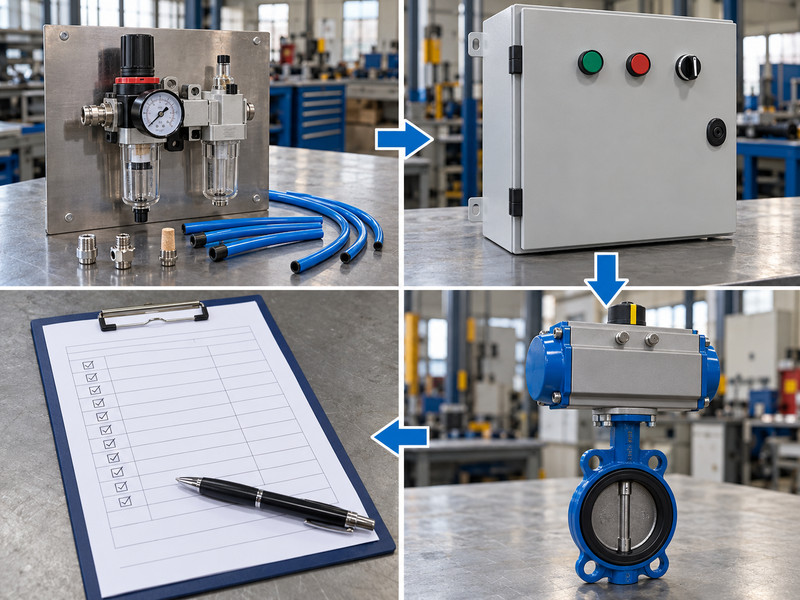
Keep the valve configuration, actuator sizing, interfaces, control function, and accepted settings under change control. A double acting actuator for butterfly valve systems can behave differently after a seemingly small solenoid or regulator substitution. Review replacements against the requirements that the original assembly passed.
Which changes need another system check?
A different actuator may change output and air demand; a different solenoid may change rest-state behaviour or flow capacity. Revised feedback hardware can alter the electrical interface, and a seat change can alter compatibility or torque. Retain the final component list, drawings, control narrative, test records, and maintenance instructions together. Give procurement and maintenance a clear route for submitting alternatives so the next repeat order does not silently change the accepted operating sequence.
- Keep mechanical, pneumatic, and electrical revisions connected.
- Reassess substitutes against their effect on system behaviour.
- Retain accepted deviations and the final handover package.
| Change | Possible consequence | Review needed |
|---|---|---|
| Actuator or seat | Different torque or air demand | Mechanical and operating cases |
| Solenoid or regulator | Different movement or failure response | Pneumatic and control sequence |
| Feedback device | Different signal behaviour | Electrical interface and acceptance test |
Key takeaway: Share your process sequence, minimum air supply, and control requirements when you contact us. RUITO can review the package interfaces and identify information still needed for selection.
10. What should system designers ask before release?
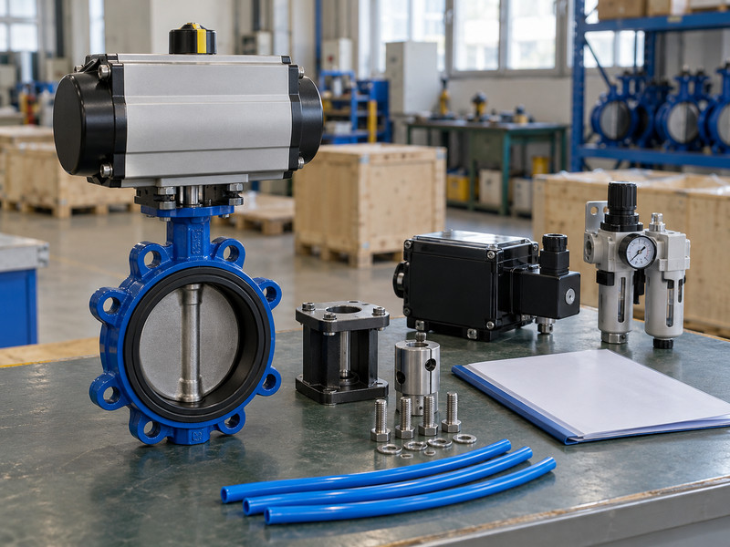
Use these questions when specifying a double acting actuator for butterfly valve systems.
- Q1: Can I define fail closed in the purchase order alone? You can state the requirement, but the selected hardware and complete system must provide and verify that response under the specified failure conditions.
- Q2: How do I know if factory testing covers my control logic? Compare the test arrangement and sequence with the actual requirement. An isolated package test cannot establish behaviour of site controls that were not included.
- Q3: What’s the best feedback signal? Use the signal that satisfies the controller, environment, and operating requirement. Verify it against actual valve position at the receiving point rather than choosing by habit.
- Q4: Can I change the solenoid without reviewing the valve? Only after assessing the effect on air capacity, movement, rest state, and restart behaviour. A replacement can change assembly performance without changing the valve body.
- Q5: Can a double-acting package have a safety function? It may form part of an engineered system, but the applicable function requires its own assessment, architecture, documentation, and verification. Actuation type alone does not establish qualification.