
Fix a double acting pneumatic butterfly valve by checking its air supply, directional control, mechanical movement, and feedback in a defined sequence. Raising regulator pressure before finding the cause can overload the drive or hide a restriction. If a valve opens correctly but closes slowly, compare the two working air paths and their exhaust conditions. Use the approved assembly instructions and isolate stored energy before disconnecting equipment or working near the disc.
1. Why can a double acting pneumatic butterfly valve fail?
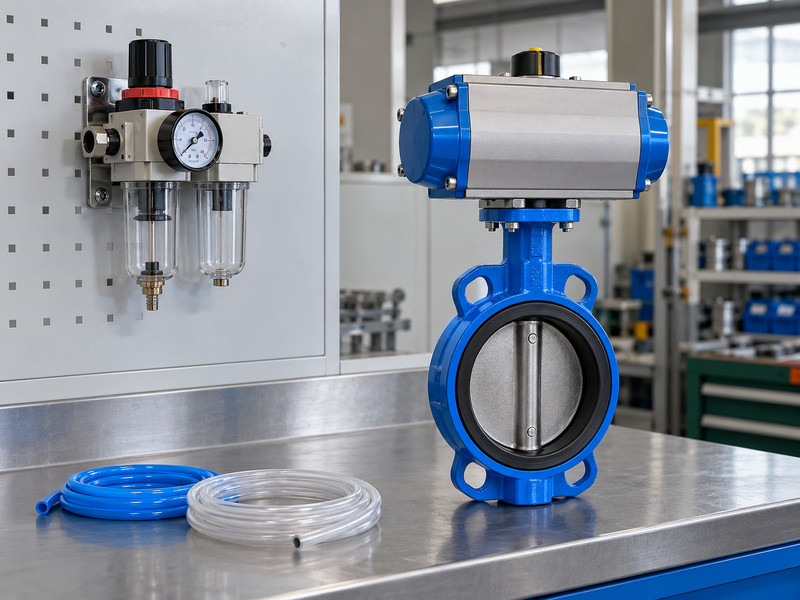
A double acting pneumatic butterfly valve can stop moving because of pneumatic restrictions, incorrect control signals, mechanical interference, or process load. Those causes require different remedies. Check the installed configuration and reported symptom before replacing parts. Begin by identifying the exact valve, actuator, controls, and operating conditions.
How do you make the fault description useful?
Note whether the fault affects opening, closing, both directions, or a particular angle. Record whether it appears cold, hot, after a long closed dwell, or only when other air users operate. Compare commanded state, actual position, and feedback separately. This helps you distinguish a valve that moved without a correct signal from a valve that never moved.
- Identify every installed component and its revision.
- Record the command, movement, and feedback independently.
- Note process conditions when the fault occurs.
- Keep the original settings and observations so a later adjustment can be evaluated against a known condition.
| Observation | Possible investigation path | Useful evidence |
|---|---|---|
| Both directions fail | Common supply or mechanical condition | Dynamic pressure and isolated movement |
| One direction fails | Working path, exhaust, or directional load | Separate opening and closing observations |
| Signal disagrees | Feedback setting or connection | Actual disc and switch positions |
Key takeaway: A specific symptom record can prevent several unnecessary component replacements.
2. How should you review the air preparation unit?
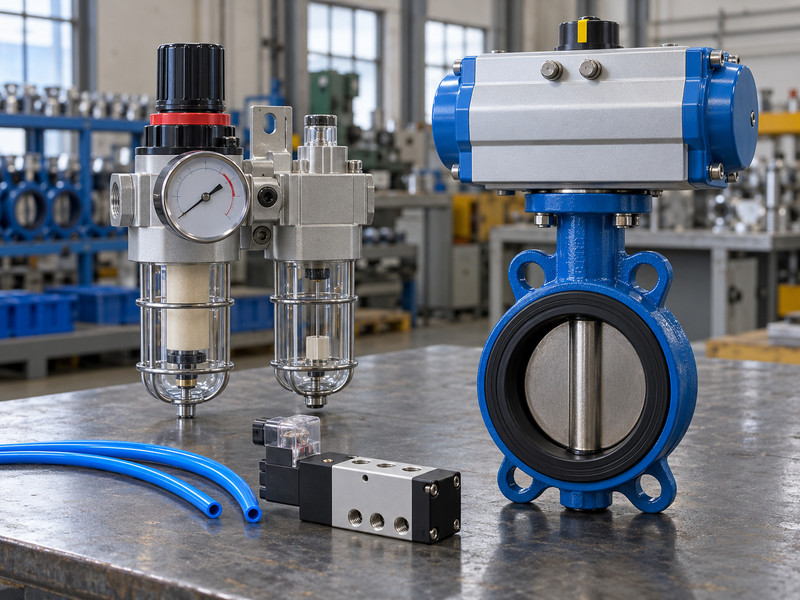
Review air preparation against the actuator and accessory requirements. A double acting pneumatic butterfly valve needs an air supply within its permitted pressure and quality limits. Contamination, water, a restricted filter, or an unsuitable regulator can affect movement even when the compressor appears to operate normally.
Which conditions should the maintenance team record?
Compare the regulator inlet and outlet conditions while the actuator strokes, where the installation permits safe measurement. Review filter condition, drainage, supply isolation, and temperature exposure. Follow the equipment instructions on air quality and lubrication; do not add oil on the assumption that every pneumatic actuator needs an external lubricator. Check that the regulator and associated fittings have enough capacity for the selected actuator and required travel time, including simultaneous demand from nearby equipment.
- Confirm specified air quality and permitted lubrication practice.
- Review filter restriction and condensate management.
- Measure the supply condition during movement.
| Air preparation item | Check | Consequence of a mismatch |
|---|---|---|
| Filter | Condition and specified filtration | Contamination or restricted supply |
| Regulator | Range, capacity, dynamic outlet condition | Reduced available actuator output |
| Drainage | Suitable arrangement for the site | Water accumulation or freezing exposure |
Key takeaway: Restore the specified air condition before changing actuator settings or hardware.
3. How do you confirm the solenoid function?
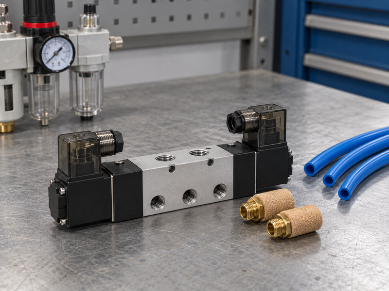
Confirm the solenoid’s documented pneumatic function, electrical supply, and de-energized state. A double acting pneumatic butterfly valve commonly uses a suitable five-port directional arrangement for on/off operation, but the exact circuit must match the selected actuator and process requirement. Exterior appearance does not establish port function.
What should you compare with the control drawing?
Check port identification, supply voltage, coil type, connector, manual override, and mounting interface. A spring-operated solenoid return and a spring-return actuator are different mechanisms; one does not imply the other. Verify how the directional valve routes supply and exhaust in each commanded state. If the assembly uses a double-solenoid or other maintained-state arrangement, confirm its behaviour after a loss and restoration of power.
- Match port connections to the documented pneumatic function.
- Confirm coil voltage and control output compatibility.
- Verify de-energized and restart behaviour for the assembly.
- Review any replacement against the approved function before reconnecting the air tubes.
| Solenoid detail | Required match | Fault to avoid |
|---|---|---|
| Pneumatic function | Approved air circuit | Reversed or blocked movement |
| Electrical supply | Actual control output | Failure to energize or coil damage |
| Rest state | Process requirement | Unexpected response after power loss |
Key takeaway: Replace a solenoid by its complete function and specification rather than by connector shape alone.
4. How can tubing cause uneven travel?
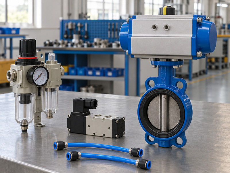
Tubing can cause uneven travel when one working path restricts supply or exhaust more than the other. In a double acting pneumatic butterfly valve, both circuits participate in movement. A kink, undersized fitting, damaged tube, or incorrect connection can change the result without changing the actuator itself.
What should you inspect along each working line?
Compare the installed tube bore, length, bends, fittings, and any flow controls with the approved arrangement. Check that tubes are supported and protected from heat, abrasion, or moving equipment. A tube can look intact while a sharp bend restricts its internal passage. Where the design includes local isolators or quick-connect fittings, confirm their operating state and suitability.
- Trace both working circuits against the drawing.
- Inspect bore restrictions, bends, and damaged fittings.
- Protect tubing from vibration and nearby hot surfaces.
- Use the actuator’s documented port arrangement when checking direction; avoid trial swapping that can produce unexpected valve movement.
| Finding | Likely effect | Corrective review |
|---|---|---|
| Kinked tube | Restricted air movement | Routing and tube replacement |
| Long small-bore line | Added pressure loss and delay | Capacity and stroke-time calculation |
| Incorrect port connection | Wrong direction or response | Approved pneumatic schematic |
Key takeaway: A complete tubing inspection includes the exhausting circuit as well as the pressurized circuit.
5. Why should you check the exhaust path?
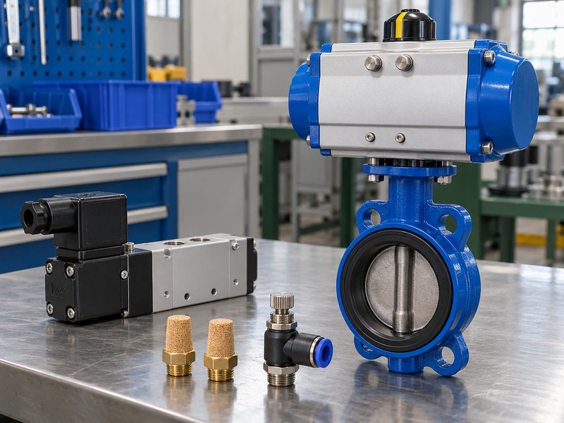
Check the exhaust path because trapped or restricted outgoing air can oppose actuator movement. A double acting pneumatic butterfly valve may receive acceptable inlet pressure yet move slowly if the opposite circuit cannot discharge as intended. Exhaust silencers and flow controls are part of the operating circuit.
When should speed adjustment be reviewed?
A deliberate exhaust restriction may control travel speed, but an incorrect setting or clogged silencer can extend the stroke unexpectedly. Review the specified adjustment method and record changes. Avoid removing restrictions merely to obtain the fastest movement; the process may require controlled closure to limit transients. If exhaust is routed to another location, include that piping and any backpressure in the review.
- Inspect silencers and routed exhaust lines for restrictions.
- Confirm the purpose of each flow-control setting.
- Retest both travel directions after an adjustment.
- Recheck opening and closing after corrective work because the two strokes may respond differently.
| Exhaust feature | Operating effect | Verification |
|---|---|---|
| Silencer | Adds a defined flow restriction | Clean condition and suitability |
| Flow control | Adjusts movement where designed | Agreed stroke-time test |
| Remote exhaust | Can add backpressure | Complete discharge-path review |
Key takeaway: Restore the intended exhaust arrangement instead of judging operation from inlet pressure alone.
6. How do you distinguish movement from feedback?
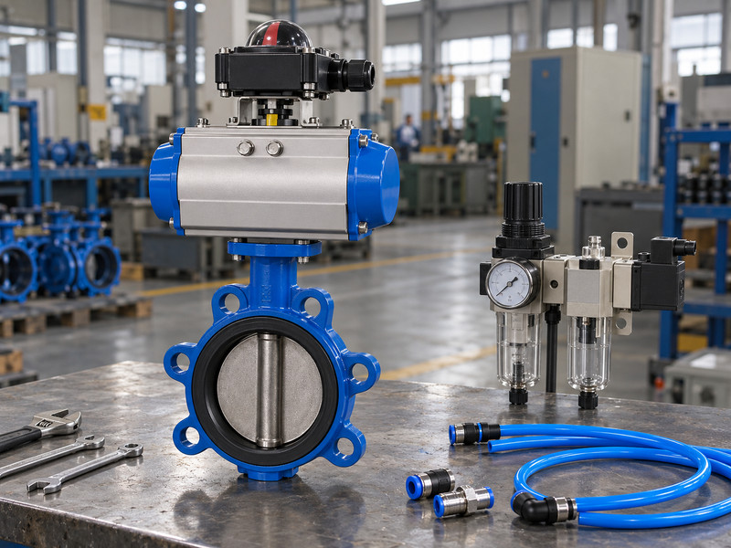
Distinguish actual movement from feedback by checking the disc position and the corresponding control signal independently. A double acting pneumatic butterfly valve may move correctly while a limit switch remains misadjusted or incorrectly connected. Conversely, a switch can indicate an actuator position even if the drive connection to the valve is faulty.
Which checks belong in the signal test?
Confirm actuator-to-valve coupling engagement and mechanical indexing before setting switches. Then verify each end-position signal at the intended receiving point, including the required electrical characteristics. Keep intermediate travel separate from end-position confirmation. If the design uses a positioner, review its feedback, calibration, and failure settings under the applicable instructions.
- Verify the mechanical drive before adjusting indication.
- Test the signal at the receiving control input.
- Check feedback after both opening and closing commands.
- Do not change a switch to conceal incomplete travel; resolve the movement problem before accepting the signal.
| Check | What it establishes | Remaining limitation |
|---|---|---|
| Disc observation | Actual mechanical position | Does not measure seat leakage |
| Local indicator | Correctly indexed drive indication | Depends on drive integrity |
| Remote signal | Electrical feedback reaches the controller | Does not prove every process condition |
Key takeaway: A correct signal should follow verified movement rather than substitute for it.
7. What should a commissioning test include?
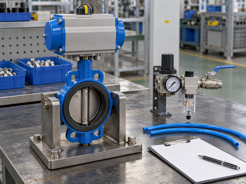
Commissioning should verify safe mechanical travel, correct air routing, commands, feedback, timing, and the agreed failure response. A double acting pneumatic butterfly valve also needs the relevant pressure-integrity and closure acceptance checks. Keep those requirements separate; a contract-selected pressure-test method such as ISO 5208 addresses a defined scope rather than the complete operating sequence.
How should you sequence the checks?
Confirm flange alignment, disc clearance, supports, and actuator access before applying operating commands. Follow the installation instructions for a wafer butterfly valve, including the appropriate mating bores and assembly procedure. Then test the pneumatic and electrical functions under controlled conditions. Record actual supply pressure, movement time, end positions, and test limitations.
- Complete installation checks before functional cycling.
- Record conditions and acceptance limits for each test.
- Assign responsibility for any remaining loaded checks.
- If process differential pressure affects the requirement, identify which loaded checks can be demonstrated and which remain conditional before process release.
| Stage | Test focus | Record |
|---|---|---|
| Mechanical | Alignment and disc travel | Installation inspection |
| Functional | Commands, air paths, feedback | Operating sequence results |
| Process release | Relevant loaded duty | Accepted checks and remaining actions |
Key takeaway: Commissioning should leave a record of verified conditions and clearly assigned open actions.
8. How should you investigate a recurring fault?
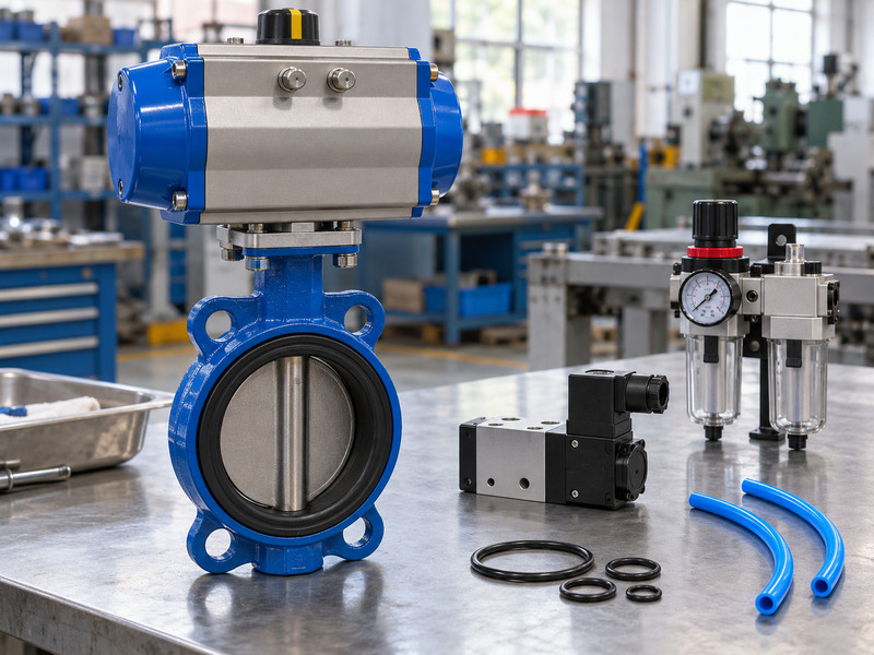
Investigate recurring faults by comparing observations under the conditions that trigger them. A double acting pneumatic butterfly valve that fails only after a long dwell or during peak air demand needs a different investigation from one that always stops at the same angle. Preserve the evidence before changing several settings at once.
Which changes should you make one at a time?
Review air pressure, control commands, actual travel, process conditions, and any recent maintenance. Inspect for seat incompatibility, deposits, shaft or coupling issues, and adjacent interference where the evidence points that way. An actuator upgrade cannot correct a disc striking a mating bore. After each approved correction, repeat the relevant test and compare the result.
- Record when the fault occurs and what changed beforehand.
- Test one suspected cause with a defined observation.
- Update configuration records after an approved correction.
- Keep replaced component identification and the revised assembly record so a later repeat order does not restore the original fault.
| Recurring condition | Review focus | Record to preserve |
|---|---|---|
| Peak demand | Dynamic air supply | Pressure and timing observations |
| Long closed dwell | Valve torque and seal condition | Service and operating history |
| Same travel angle | Interference or changing load | Position and mechanical inspection |
Key takeaway: A repeatable diagnosis is more useful than a temporary improvement after several undocumented adjustments.
9. What should your operating handover contain?
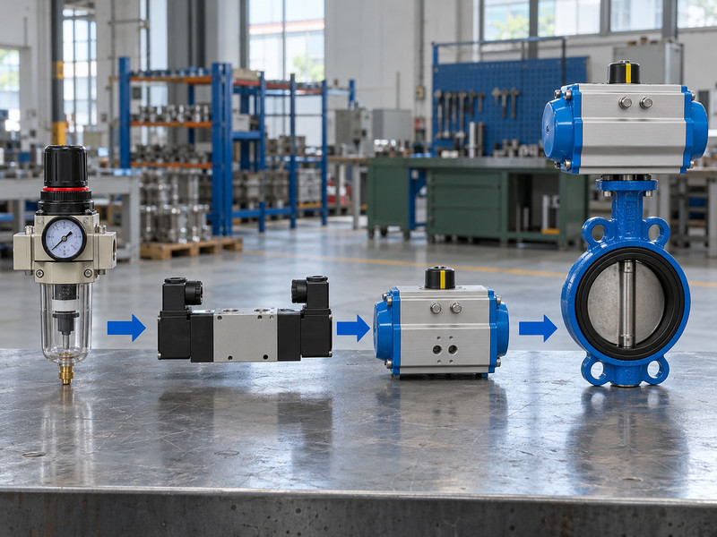
Handover should contain the approved configuration, settings, test results, maintenance instructions, and replacement requirements. A double acting pneumatic butterfly valve becomes harder to support when the installed solenoid, tubing, or feedback device differs from the original quotation. Record the final build that actually passed acceptance.
Which information helps the next maintenance team?
Retain actuator and accessory identification, the valve materials, mounting drawing, air supply range, expected movement time, and required failure behaviour. Include any restrictions on manual override use and the safe isolation procedure from the applicable instructions. List approved spare parts and the changes requiring engineering review. A maintenance team should be able to distinguish a like-for-like replacement from a change that affects torque, travel, feedback, or process response without reconstructing the assembly from old photographs.
- Keep the final pneumatic and electrical information together.
- Record accepted settings and movement tests.
- Define the review needed for substitute components.
| Handover item | Helps with | Update after |
|---|---|---|
| Final component list | Correct replacement selection | Approved substitution |
| Settings and test results | Fault comparison | Commissioning changes |
| Isolation and service instructions | Planned maintenance | Equipment configuration changes |
Key takeaway: Give RUITO your duty, air supply, signals, and observed fault when you contact us. Those details support a focused review of the complete valve package.
10. What should operators ask before making adjustments?
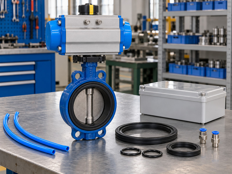
Ask these questions before changing a double acting pneumatic butterfly valve or its controls.
- Q1: Can I increase pressure until the valve moves? No. Stay within the approved limits and investigate the cause. Higher output can damage the shaft, coupling, bracket, or seat without correcting the fault.
- Q2: What’s the best way to speed up a slow stroke? Check dynamic supply and both air paths before changing settings. The required stroke time must also suit the process and the equipment’s operating limits.
- Q3: Can I trust an open or closed light? Only after the signal has been checked against actual valve movement. The signal does not independently establish coupling integrity or seat leakage performance.
- Q4: How do I know if the solenoid replacement is suitable? Compare pneumatic function, voltage, flow capacity, interface, environment, and rest-state behaviour with the approved specification. Similar appearance is insufficient.
- Q5: Can I cycle the valve during maintenance? Only under the site’s approved isolation and testing procedure. Keep people and tools clear of moving parts and address pneumatic, process, electrical, and any other stored energy.