
Fix pneumatic butterfly valve with positioner calibration mistakes by checking the assembly and utilities before authorized travel adjustment. Follow the selected manual and site isolation procedure, then verify motion against the approved drawing. Calibration can move the valve through its stroke; prepare before supplying drive energy.
Your display reaches its requested percentage, but the installer sees the disc stop short of the expected position. Repeating auto-calibration can hide the reason if nobody checks coupling orientation, travel clearance and the air supply. Stop the acceptance check and compare the assembly with its approved records.
1. How do you prepare a pneumatic butterfly valve with positioner?
Prepare a pneumatic butterfly valve with positioner by defining an authorized, isolated test arrangement and the permitted movement before calibration. Qualified personnel should follow the selected manuals and site procedure for electrical, pneumatic and process isolation. Keep hands and tools clear of the mechanism whenever drive energy is available, including during automatic or unexpected movement.
What should the test boundary establish?
Identify process connections, stored pneumatic or spring energy, the intended operating range and the controls available to the authorized tester. Arrange process isolation and pressure equalization or draining as required by the accepted procedure before travel calibration. Verify the boundary and clearance before energizing; neither a bench label nor an out-of-service screen establishes physical isolation.
- Use an approved test arrangement and qualified personnel.
- Address process pressure and stored drive energy explicitly.
- Keep personnel, tools and loose items outside the movement envelope.
Key takeaway: A verified test boundary lets the technician calibrate travel without relying on a software mode to control physical energy or movement.
| Check | What you should confirm |
|---|---|
| Authorization | The accepted procedure and responsible test personnel |
| Isolation | Process, electrical and pneumatic boundaries as required |
| Movement | Clear envelope and controlled access during energization |
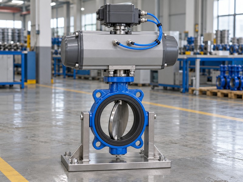
2. How do you inspect a pneumatic butterfly valve with positioner?
Inspect a pneumatic butterfly valve with positioner against the approved assembly drawing before using its displayed position as evidence of disc travel. Verify the valve, actuator, positioner and their coupling identities. Incorrect orientation, a loose connection or an unsuitable sensor range can leave the indicated movement different from the mechanical relationship your order requires.
Which mechanical checks come before adjustment?
With the required isolation in place, inspect mounting, coupling engagement, fasteners and the accepted travel envelope according to the assembly instructions. Check that the actual disc, adjacent bore and fixtures have the required clearance. Identify any transport damage or substituted bracket before you proceed. Retain the inspection record so motion tests concern the approved assembly and its verified connections.
- Match supplied parts and revisions with the approved drawing.
- Inspect mounting, engagement and feedback orientation under isolation.
- Resolve clearance, damage and substitution questions before energization.
Key takeaway: Mechanical inspection gives the calibration a known motion path and prevents software adjustment from disguising an incorrect or damaged assembly.
| Check | What you should confirm |
|---|---|
| Identity | The accepted valve, actuator and accessory revisions |
| Mechanical path | Approved coupling, bracket and sensing arrangement |
| Clearance | Permitted disc and operator motion through the test range |
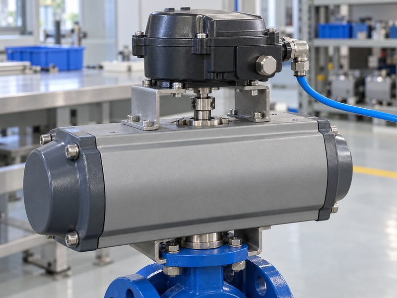
3. How do you supply a pneumatic butterfly valve with positioner?
Supply a pneumatic butterfly valve with positioner using the accepted pressure, air-quality and electrical requirements of the selected assembly. Confirm those requirements from the actual manuals and utility schedule. Another installation’s regulator setting cannot establish the supply for this test, and a static gauge reading does not settle what pressure remains available during movement.
What utility readings should you record?
Record supply conditions at the package boundary. Check the specified filter, regulator, tubing and pneumatic paths, then observe supply under the accepted stroking procedure. Investigate unexpected pressure loss or an incorrect port connection before changing tuning. Process fluid and instrument air have separate qualification and supply requirements.
- Use the selected manuals’ supply and air-quality requirements.
- Verify regulator, tubing and working-port connections.
- Record supply conditions during the accepted movement check.
Key takeaway: Verify utilities before tuning so a restricted supply or incorrect pneumatic connection does not become an apparent calibration problem.
| Check | What you should confirm |
|---|---|
| Air quality | The selected device’s contamination and dryness limits |
| Supply path | Accepted regulator, tubing and port arrangement |
| Available pressure | Recorded conditions during the approved test demand |
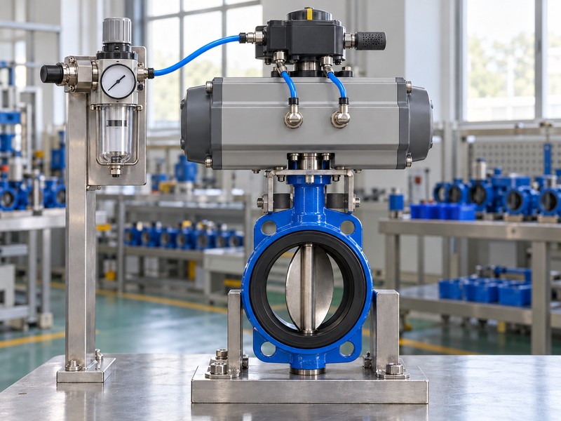
4. How do you wire a pneumatic butterfly valve with positioner?
Wire a pneumatic butterfly valve with positioner from the approved terminal schedule and selected device manual with the required isolation maintained. Identify the command input, electrical supply and position output independently. A current input and a current feedback output can have different circuit roles, and a device may use a power arrangement unlike the previous installation.
How should you verify the command relationship?
Follow the authorized checks after wiring inspection. Compare the configured input range and direction with the accepted closed and open positions, and confirm which feedback circuit reports actual travel. A valid low-end command such as 4 mA is separate from signal-fault detection. Record mapping and settings so you can investigate reversed indication without swapping connections on an energized assembly.
- Follow the approved terminal and electrical isolation requirements.
- Identify command, power and feedback functions separately.
- Record input direction and the configured endpoint relationship.
Key takeaway: A recorded command relationship lets you distinguish wiring or direction errors from a mechanical inability to reach the requested position.
| Check | What you should confirm |
|---|---|
| Wiring | Actual terminal assignments and accepted circuit roles |
| Mapping | Command values tied to the correct travel direction |
| Indication | The selected output and its verified position relationship |
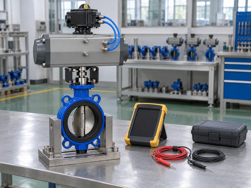
5. How do you calibrate a pneumatic butterfly valve with positioner?
Calibrate a pneumatic butterfly valve with positioner with the selected device’s authorized travel procedure after its mounting, utilities and isolation checks pass. Automatic routines can seek the endpoints and move the valve through its stroke. Keep the movement envelope clear and use the actual assembly’s accepted travel limits rather than forcing a displayed percentage to match an assumed disc position.
What should you do if adjustment fails?
Record the error and test conditions before retrying. Check the manual’s diagnosis against supply, coupling, sensor range and physical travel, then resolve the identified cause through the approved work procedure. Successful endpoint learning does not approve a new closing stop, excessive seat compression or a stronger drive. Save accepted settings and results with the assembly revision for later inspection.
- Run the actual device procedure within approved travel limits.
- Record errors before making model-specific corrective changes.
- Retain settings and results against the supplied assembly revision.
Key takeaway: Calibration relates command and measured travel to the accepted assembly; it cannot approve mechanical changes that the drawing and duty review exclude.
| Check | What you should confirm |
|---|---|
| Readiness | Passed isolation, mounting and utility checks |
| Adjustment | Selected manual procedure and accepted physical limits |
| Result | Recorded completion or an identified unresolved error |
6. How do you test a pneumatic butterfly valve with positioner?
Test a pneumatic butterfly valve with positioner after calibration by comparing the accepted commands with actual travel under the agreed bench conditions. Verify direction, endpoints and intermediate responses required by the inspection plan. The result describes the assembly’s tested position behavior; it does not measure system flow or replace later process-loop commissioning.
Which observations belong in the response record?
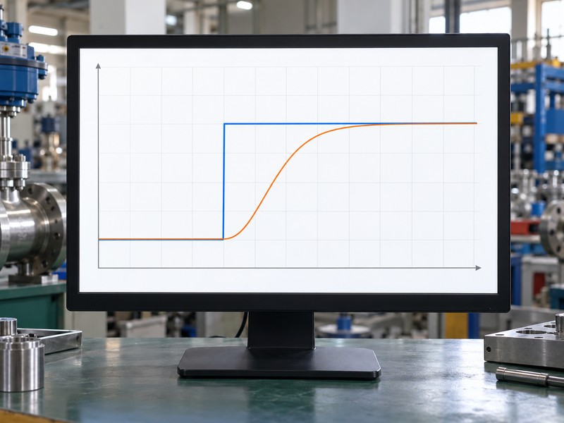
Record command, indication, mechanical movement and utility conditions together. Check both directions where the acceptance plan requires them and resolve any mismatch. The chart is illustrative; obtain actual assembly records. Define a measurement method and conditions for any timing or position-tolerance requirement.
- Compare commanded and verified mechanical positions.
- Record utility conditions and movement direction with the result.
- Use agreed methods for any timing or tolerance requirement.
Key takeaway: A response record shows how the assembly moved under its bench conditions without implying a flow result or unspecified precision guarantee.
| Check | What you should confirm |
|---|---|
| Command | The actual input and intended position request |
| Travel | Verified indication and mechanical movement relationship |
| Conditions | Utility state and the agreed test procedure |
7. Why does a pneumatic butterfly valve with positioner hunt?
A pneumatic butterfly valve with positioner can hunt when the position loop or wider process loop repeatedly drives it around the requested condition. Identify which signal oscillates before prescribing a remedy. Compare command, travel and supply observations with the process measurement, because a stable bench position and an unstable site process point to different investigations.
How do you locate the oscillation source?
Preserve the existing settings and collect the relevant traces. Check mounting, coupling, air supply and manual mode before reviewing the selected positioner’s tuning guidance. If the command itself cycles during site operation, ask the process-control team to examine that loop’s sizing, measurement and controller conditions. Increasing positioner gain is not a universal remedy; model-specific tuning should follow diagnosis and the authorized procedure for the affected loop.
- Compare command, travel, supply and process traces.
- Check mechanical and utility conditions before tuning changes.
- Assign process-loop investigation when the request itself oscillates.
Key takeaway: Locate the oscillation before changing settings so positioner adjustment does not conceal an unresolved mechanical, utility or process-control problem.
| Check | What you should confirm |
|---|---|
| Position evidence | Command and travel observations on the same basis |
| Assembly evidence | Mounting, modes and air-supply condition |
| Process evidence | Measurement and controller behavior during site operation |
8. Why does a pneumatic butterfly valve with positioner stick?
A pneumatic butterfly valve with positioner can stick when friction, binding, coupling play or inadequate drive conditions prevent the expected movement. Identify the mechanical or utility cause before repeating calibration. A sensor can report actuator motion while a drive connection leaves the disc response unresolved, so compare the whole assembly against its approved motion path.
What should you inspect before changing the drive?
After the required isolation, inspect the accepted mounting and valve joint for misalignment, incorrect compression or damaged components. Review the valve’s torque demand against available actuator output at the actual test conditions, including return torque where relevant. Do not compensate for binding with an unapproved larger actuator or travel stop. Treat a material, coupling or drive change as an engineering revision with its required reassembly and acceptance checks.
- Inspect alignment and approved joint assembly under isolation.
- Compare full-stroke torque demand with available drive output.
- Review substitutions and repairs before reassembly acceptance.
Key takeaway: Correct the cause of poor movement before adjusting settings or drive size, then verify the revised assembly against its accepted requirements.
| Check | What you should confirm |
|---|---|
| Mechanics | Approved alignment, coupling and valve installation |
| Drive | Available output matched to actual torque demand |
| Correction | Authorized repair or revision with required verification |
9. Can a pneumatic butterfly valve with positioner fail safely?
A pneumatic butterfly valve with positioner can meet a specified failure response only when the complete arrangement has the required capability and verification. Review loss of instrument air, command signal and electrical power separately. A springless double-acting actuator has no universal assured endpoint or indefinite hold, and normal low command is not automatically a fault event.
How should the failure check be controlled?
Use the approved isolated test procedure and selected manuals. Identify which utilities remain for each event, then record the pneumatic arrangement, relevant settings and any solenoid, lockup or stored-energy dependency. Qualified personnel should perform only the agreed checks with controlled access to the movement envelope. Restore and verify the accepted state before further testing, and do not infer combined-failure behavior by combining records from separate single-event tests.
- Check each specified lost utility as a distinct event.
- Record remaining energy and accessory dependencies.
- Use authorized isolation and controlled access during verification.
Key takeaway: Failure verification needs a defined event and complete assembly, allowing you to assess the tested response without claiming universal safe behavior.
| Check | What you should confirm |
|---|---|
| Event | The exact lost utility and utilities still available |
| Configuration | Accepted porting, action and fault settings |
| Result | Observed response against the agreed requirement |
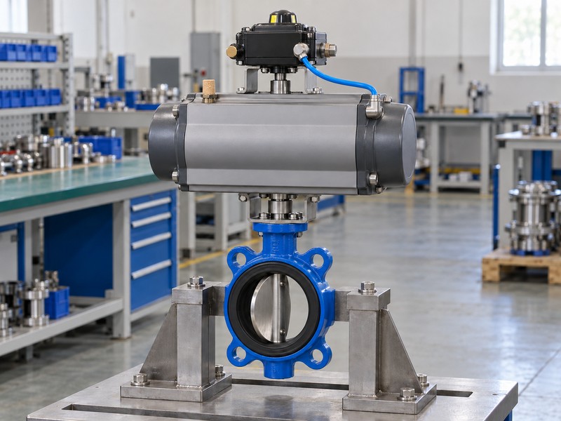
10. How do you release a pneumatic butterfly valve with positioner?
Release a pneumatic butterfly valve with positioner after the responsible reviewer accepts its identity, calibration, travel and required failure-event records. Keep valve integrity checks and site process-loop acceptance as separate obligations. A completed bench routine does not demonstrate leakage, flow accuracy, cavitation freedom or the final controller’s performance under the installed operating conditions.
What belongs in the commissioning handover?
Retain the assembly drawing, manuals, utility and signal schedules, accepted settings, test observations and closed corrective actions. State which checks still require the site’s authorized commissioning team and defined process measurements. A replacement positioner or coupling needs compatibility review and the specified verification before return to operation.
- Retain settings and test records against the actual assembly.
- Close corrective actions and identify pending site checks.
- Review later accessory or mechanical changes before reuse.
Key takeaway: A complete handover preserves what bench testing established and gives the site team an explicit basis for the remaining commissioning work.
| Check | What you should confirm |
|---|---|
| Bench release | Accepted calibration and assembly-function records |
| Valve integrity | The separate agreed pressure and leakage evidence |
| Site handover | Defined pending process checks and change-control records |
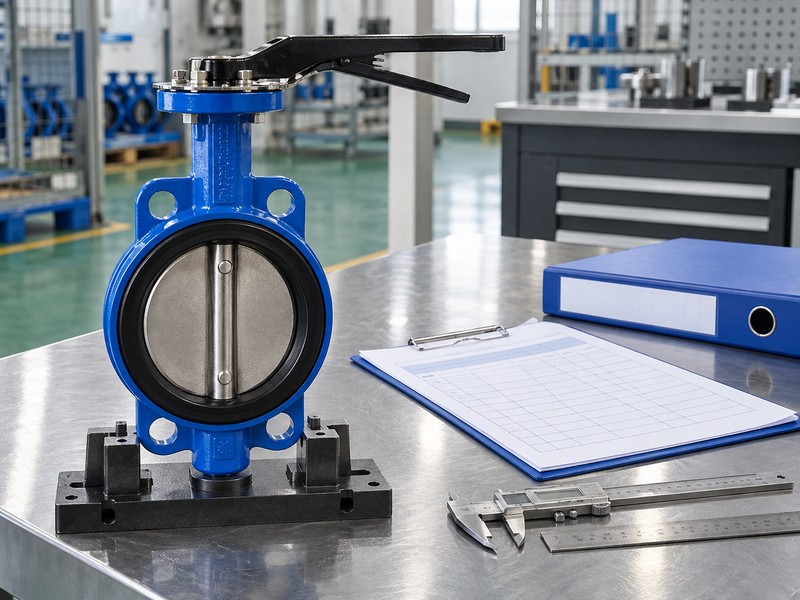
Send RUITO the assembly identity, approved drawings, utility conditions, reported errors and your recorded motion observations. We can review the valve and interface configuration and clarify the appropriate inspection scope for your enquiry. Contact us before approving a replacement accessory or returning an assembly with unresolved travel or failure behavior to service.
FAQ
Q1: Can I auto-calibrate while the valve remains on a live process?
Follow the selected manual’s isolation requirements. Full-stroke routines can affect process pressure or flow.
Q2: How do I know if the display matches the disc?
Verify the mechanical path and travel relationship. The display cannot resolve an incorrect or loose coupling.
Q3: Can I fix hunting by increasing gain?
Do not assume that remedy. Diagnose command, travel, air and process behavior, then follow the affected device’s approved tuning procedure.
Q4: What’s the best record to send for a calibration problem?
Send the assembly identity, settings, error, supply conditions and motion observations. Those details let engineering review the actual configuration.
Q5: Can a successful bench calibration prove flow accuracy?
No. Verify flow through the defined process measurement and installed control-loop acceptance procedure, using an approved valve operating envelope.