
Fix factory audit mistakes by asking your butterfly valve with positioner factory to trace an identified assembly through its actual work instructions and inspection records. Follow the valve, actuator, positioner and mounting parts together. Your audit should establish who performs each operation, how inspectors check it and which records authorize the completed product’s release.
If a tour shows an actuator turning on a bench, you may still receive a valve with different tubing, a loose feedback coupling or calibration settings that nobody can identify. Those differences can interrupt commissioning and make the original approval difficult to reproduce. Choose one assembly, review its accepted revision and follow its physical production route through inspection and packing.
1. How do I verify a butterfly valve with positioner factory?
Verify a butterfly valve with positioner factory by matching the business identity and site with an identified assembly’s production route. Ask which valve, mounting, pneumatic and calibration operations the site performs, and which components it purchases. You need an accountable party for the assembled configuration and release decision even when outside manufacturers supply the instruments.
What should the auditor request at the start?
RUITO’s Shijiazhuang team manages valve design, machining, assembly, inspection and delivery. Establish the actual process boundary. Request the selected assembly ID, work order, component list and accepted drawings during a live or physical review, with the responsible staff available. Illustrations in this guide explain inspection topics; they cannot verify a real facility, employee action or measured result.
- Match the legal entity and stated production site.
- Identify internal operations and purchased component responsibilities.
- Select one assembly for the complete audit route.
Key takeaway: A factory audit starts with the actual manufacturing boundary and a product that you can trace through it.
| Check | What you should confirm |
|---|---|
| Identity | Business, site and order responsibility match |
| Route | Internal and external operations are identified |
| Product | Assembly ID connects with its work order |
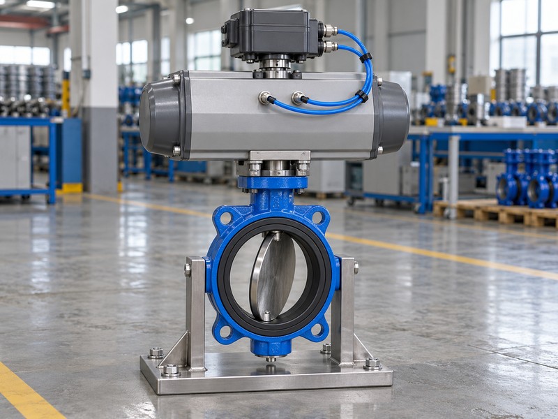
2. How does a butterfly valve with positioner factory trace parts?
A butterfly valve with positioner factory traces parts by connecting received components and valve materials with the approved assembly definition. Check the body, disc, shaft, seat, actuator and positioner identities, including their relevant variants. A certificate for a casting cannot identify the instrument or establish that the factory received the intended feedback and pneumatic configuration.
Where should purchased-component controls appear?
Follow one component from receipt to the work order and assembly station. Check the acceptance record. For factory-machined parts, compare the drawing revision and initial-piece measurements; for purchased instruments, inspect identification, document availability and accepted substitutions. Ask who rejects an incorrect variant and who resolves an outside manufacturer’s defect, so a purchased component cannot bypass the final assembly’s inspection responsibility.
- Match received parts with the approved component list.
- Trace relevant batches, variants and machining revisions.
- Review segregation and authorization for component substitutions.
Key takeaway: Traceability should identify the parts inside the finished assembly and the factory’s acceptance decisions for purchased components.
| Check | What you should confirm |
|---|---|
| Valve parts | Materials and machining records match the definition |
| Instruments | Actual variants and associated documents are identified |
| Responsibility | Rejected parts and outside defects have owners |
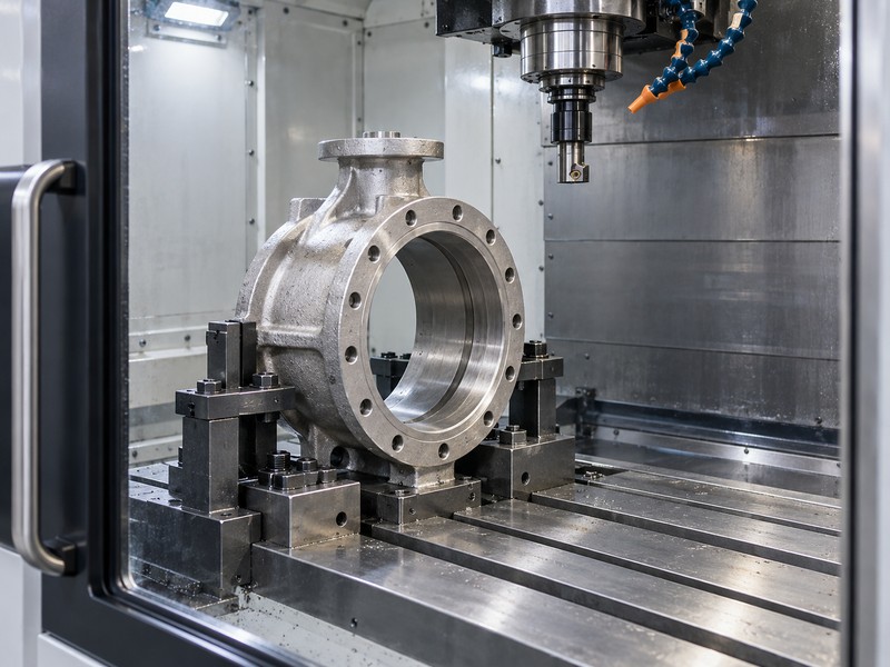
3. How does a butterfly valve with positioner factory mount units?
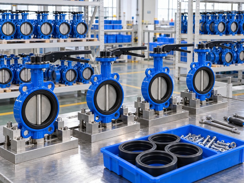
A butterfly valve with positioner factory mounts units using the approved bracket, coupling, alignment features and assembly instructions. Inspect the fixture or jig alongside the actual shaft interfaces and part revision. A tidy bracket cannot prove correct feedback engagement, acceptable shaft loading or freedom from binding across the permitted travel.
Which checks belong at the mounting station?
Ask the operator to identify the mounting drawing and the setup used for that assembly. Follow the shaft connection. Check the valve-drive coupling, positioner feedback engagement and fastener requirements against the selected instructions, then compare observed movement with the physical disc orientation. Gauges or fixture checks should address defined dimensions, with inspection results linked to the assembly.
- Match mounting parts and fixture references with drawings.
- Inspect coupling engagement and feedback alignment.
- Record the specified mechanical and dimensional checks.
Key takeaway: Review mounting against the actual shaft connections and the assembly’s defined inspection basis.
| Check | What you should confirm |
|---|---|
| Setup | Fixture and drawing fit the actual assembly |
| Connection | Couplings and feedback engage without binding |
| Check | Physical orientation and recorded dimensions agree |
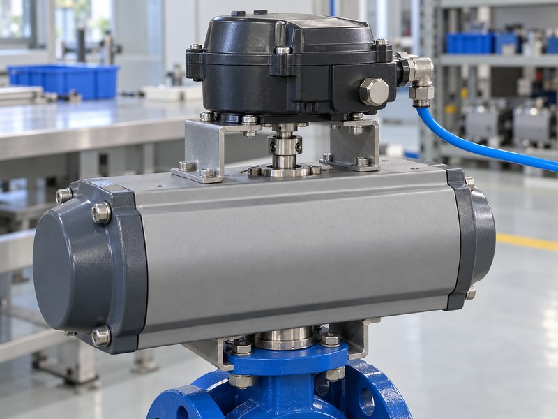
4. How does a butterfly valve with positioner factory check torque?
A butterfly valve with positioner factory checks torque suitability by matching the assembled components with the approved valve-demand and actuator-output basis. Verify the seat configuration, closing differential pressure, stroke and minimum air-supply conditions. A no-load stroke demonstration cannot establish that the same assembly moves through its required travel under the intended process load.
What can an auditor verify on the floor?
Compare actual actuator identification and mechanical parts with the engineering sizing record. Check the test boundary. If the acceptance plan requires loaded movement, review its procedure, fixture, measurement method and recorded conditions rather than treating an empty bench run as that result. For spring return, verify the relevant return configuration and torque basis through the stroke, with shaft and coupling limits included in the review.
- Match installed components with the accepted sizing basis.
- Identify supply and load conditions in movement records.
- Review return torque and mechanical load limits.
Key takeaway: The audit should show that the built assembly matches its engineering basis and that test records describe the load tested.
| Check | What you should confirm |
|---|---|
| Configuration | Seat, actuator and coupling match sizing inputs |
| Conditions | Minimum supply and applicable load are identified |
| Coverage | Bench and required loaded checks remain distinct |
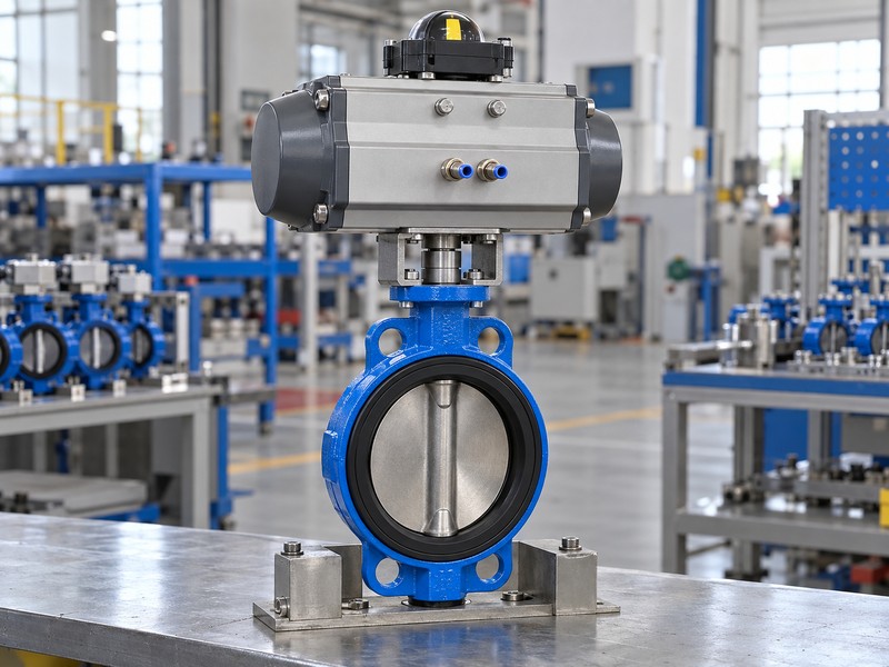
5. How does a butterfly valve with positioner factory pipe air?
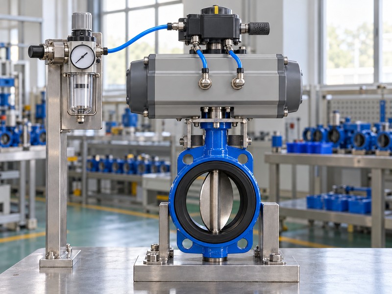
A butterfly valve with positioner factory pipes air according to the approved pneumatic diagram and selected actuator-positioner variant. Trace supply, output ports, actuator connections and exhaust paths on the actual unit. Confirm filter-regulator selection, tubing support and access against the specified air requirements.
Which physical air-circuit checks should you follow?
Ask the assembler to explain how the installed connections match the controlled diagram. Follow each identified line. Inspect the stated cleanliness, dryness, fittings and restraint requirements, then review any agreed leakage or functional check with its pressure and acceptance basis. A solenoid, lockup or reservoir changes the circuit definition and needs its own identified parts and operating conditions in the inspection plan.
- Trace supply, output and exhaust paths against diagrams.
- Check tubing support and specified air preparation.
- Identify accessory functions and pneumatic inspection conditions.
Key takeaway: A physical air-circuit audit connects the actual tubing and accessories with the assembly’s approved operating and failure definitions.
| Check | What you should confirm |
|---|---|
| Porting | Connections match the selected pneumatic variant |
| Supply | Air preparation fits the actual component requirements |
| Circuit | Accessories and agreed checks retain traceable identity |
6. How does a butterfly valve with positioner factory calibrate?
A butterfly valve with positioner factory calibrates using the selected device manual, an authorized movement procedure and identified assembly settings. Review the work instruction before witnessing automatic adjustment because calibration can move the valve. The responsible team must establish isolation, movement clearance and the permitted utilities before starting a routine or changing the travel range.
What should the calibration record preserve?
Compare the commanded direction, observed shaft movement and displayed endpoints against the accepted procedure. Check the physical position too. Inspect the input type and any separate feedback output, noting that 4 mA normally represents the configured low command on a 4–20 mA input. Retain assembly ID, device identification, procedure revision and accepted settings so a later operator can locate the same configuration.
- Review movement authorization and selected manual references.
- Compare indicated endpoints with physical shaft travel.
- Retain command settings and the calibration revision.
Key takeaway: Calibration evidence should connect an authorized procedure and recorded settings with the physical movement of the identified assembly.
| Check | What you should confirm |
|---|---|
| Preparation | Isolation and movement conditions are authorized |
| Travel | Direction and physical endpoints match indication |
| Record | Assembly, device and accepted settings are identified |
7. How does a butterfly valve with positioner factory test faults?
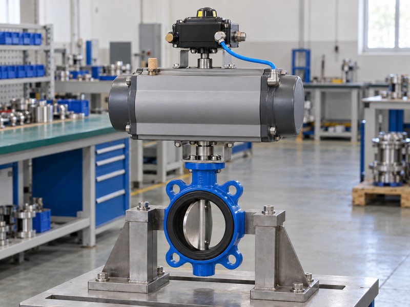
A butterfly valve with positioner factory tests faults using an agreed event matrix that separates air loss, signal loss and electrical-power loss. For each event, state which utilities remain and what action the complete assembly must demonstrate. Inspect the actual springs, pneumatic ports and accessories before accepting a recorded failure-action label.
What should you witness during an event check?
Use the authorized isolated test procedure and record the assembly’s movement under its stated conditions. Follow the remaining energy sources. A springless double-acting actuator provides no universal endpoint or indefinite hold, and electrical fail-freeze behaviour cannot establish the response to air loss. Any tested action should remain tied to the actual variant and circuit, with deviations resolved before the inspector signs the result.
- Define the failed utility and remaining supplies.
- Match observed action with the actual installed circuit.
- Record conditions, deviations and the acceptance decision.
Key takeaway: A witnessed fault check supports the event and conditions tested for the identified assembly, without extending to every supply failure.
| Check | What you should confirm |
|---|---|
| Event | Air, signal and power losses are separate |
| Hardware | Springs, porting and accessories match the record |
| Result | Observed action meets the agreed conditions |
8. How does a butterfly valve with positioner factory record travel?
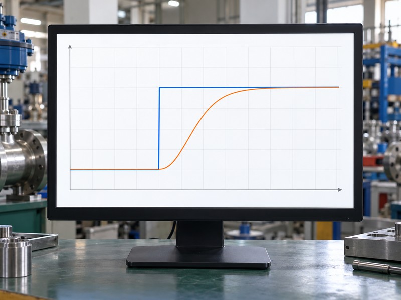
A butterfly valve with positioner factory records travel by capturing the command and measured shaft response under the agreed test conditions. Identify assembly revision, air conditions, direction, measurement method and applicable load. Define the required error, repeatability, deadband or response criteria before reviewing the traces, so the inspector has a clear acceptance basis.
How can you verify the record’s meaning?
Request the original readings and compare them with the reported result and instrument identification. Read command and position together. If movement oscillates, review feedback mounting and air behaviour alongside the command before authorizing a tuning change. The conceptual response graph illustrates shaft movement only; shaft travel cannot measure process flow, and a bench trace cannot establish performance under an untested load.
- Agree response measures and test conditions in advance.
- Connect original traces with the assembly and instruments.
- Identify bench, loaded and process evidence separately.
Key takeaway: Travel records should show how the identified assembly responded, with the inputs and conditions needed to assess its acceptance.
| Check | What you should confirm |
|---|---|
| Trace | Command and measured shaft positions are available |
| Basis | Supply, direction, load and metrics are defined |
| Scope | Reported conclusions stay within tested conditions |
9. How does a butterfly valve with positioner factory release units?
A butterfly valve with positioner factory releases units after the required valve, assembly and document checks close against the accepted inspection plan. Match the product ID with dimensions, function, calibration and relevant pressure records. Keep these acceptance categories distinct: a completed travel check cannot establish valve integrity, closed-seat leakage or approval for the intended market.
What should the final inspector connect?
Review required signatures, unresolved findings and any authorized retests before packing starts. Check the pressure report separately. A contract method such as ISO 5208 covers its specified pressure-testing scope and does not establish control accuracy. Product or accessory approvals need exact configuration and destination coverage, while management certificates describe their organizational scope; connect the accepted release records with the final box and product IDs.
- Close required inspections, findings and authorized retests.
- Separate pressure, travel and approval document scope.
- Link release evidence with products and box numbers.
Key takeaway: Release should give your receiving team the identified product and its agreed acceptance evidence.
| Check | What you should confirm |
|---|---|
| Inspection | Required results and signatures are complete |
| Scope | Each test or approval answers its own requirement |
| Delivery | Product and box IDs connect with release records |
10. How does a butterfly valve with positioner factory track changes?
A butterfly valve with positioner factory tracks changes through linked assembly instructions, drawings, component variants and accepted settings. Ask how the factory transfers sample approval into production and prevents a superseded instruction from reaching the station. Rework or a purchased-component substitution needs review when it changes mounting, signals, porting, failure behaviour or the valve duty.
What happens after a component change?
Trace a change decision to the affected work orders and required repeat checks. Follow the effective product IDs. RUITO controls valve drawings and materials through approved changes; the selected actuator-positioner package also needs a recorded configuration baseline. After work affecting feedback, tubing or settings, require the specified reinspection and calibration review before the revised assembly returns to the accepted shipment.
- Freeze the accepted sample and production instruction revisions.
- Authorize substitutions and identify their effective products.
- Repeat affected checks after rework or configuration changes.
Key takeaway: Verify that the factory preserves the accepted assembly and checks changes before repeat production.
| Check | What you should confirm |
|---|---|
| Baseline | Stations use the accepted drawings and instructions |
| Change | Authorization and effective product scope are traceable |
| Rework | Affected checks close before shipment acceptance |
Send RUITO your valve duty, proposed assembly definition and factory audit checklist. We can identify the valve manufacturing evidence and the selected component documents still needed for review. Contact us to agree the physical checks, acceptance records and release conditions before approving production.
FAQ
Q1: Can I audit the assembly process remotely?
Yes, for agreed checks. Select an identified unit and request live part, instruction and record reviews; retain any required physical or witnessed verification separately.
Q2: What’s the best way to check outsourced instruments?
Trace the installed variants. Match their identification and documents with the approved list, and verify who controls receipt, defects and substitutions.
Q3: How do I know if a calibration result is usable?
Match it with the physical assembly. Review the procedure, shaft endpoints, selected device, settings and recorded revision rather than accepting a passed-routine message alone.
Q4: Can a no-load stroke prove operation in my line?
No. It verifies its recorded bench conditions; review torque and any required loaded or process evidence for your actual duty.
Q5: Can a pressure report prove position-control accuracy?
No. Pressure integrity and seat closure have separate acceptance requirements from command and shaft-response tests.