
Fix approval mistakes by requiring your butterfly valve with positioner manufacturer to define and verify the complete assembly for your duty. Review the valve, actuator, positioner, mounting parts and accessories together. Keep the accepted configuration, performance conditions and unresolved requirements attached to the purchase order.
If a sample follows a command on a bench, your team may still find that the production assembly stalls at the available air supply or reports travel through a loose coupling. That can delay equipment commissioning and complicate fault diagnosis. Approve the engineering definition, then agree which evidence establishes mechanical fit, loaded movement, fault behaviour and production consistency.
1. What must a butterfly valve with positioner manufacturer define?
A butterfly valve with positioner manufacturer must define the complete supplied assembly and the conditions used to select it. Identify the valve construction, wetted materials, actuator, positioner, bracket, coupling and accessories. Your approval should connect that definition with the fluid, temperature, working pressure, closing differential pressure and intended operating function.
Which files establish the assembly boundary?
Request an assembly drawing, bill of materials and component-document index with matching revisions. Start with the supplied parts. RUITO’s valve engineering review addresses service, interfaces and drive selection, while the selected positioner requires its own model-specific documents. Record any components supplied or installed by your team so the acceptance plan covers their integration without attributing an untested function to the factory package.
- Identify every supplied component and approved revision.
- List buyer-installed accessories and integration responsibilities.
- Record the service inputs and unresolved decisions.
Key takeaway: Approve a defined assembly with stated operating conditions and responsibilities, rather than an accessory name attached to a valve.
| Check | What you should confirm |
|---|---|
| Assembly | Valve, drive, positioner and mounting parts identified |
| Duty | Accepted service and operating function stated |
| Boundary | Supplier and buyer responsibilities are recorded |
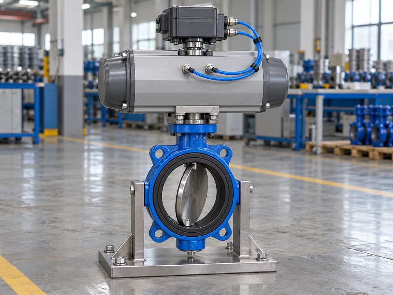
2. What does a butterfly valve with positioner manufacturer control?
A butterfly valve with positioner manufacturer uses the positioner and actuator to control commanded shaft position. The positioner compares a command with travel feedback and changes actuator output to move the shaft. Flow control also needs the appropriate process measurement and controller; a travel percentage cannot establish a measured flow percentage.
Where does your process controller belong?
Draw the command, travel feedback, actuator output and process measurement as separate connections. Check the measurement path. Confirm whether the selected device provides position control alone or a supported process-control function with a specified sensor input. Review the valve’s hydraulic sizing and installed operating range independently, since changing the accessory cannot qualify an isolation construction for every continuous throttling duty.
- Identify the command and mechanical travel feedback.
- Locate the process sensor and controlling function.
- Keep hydraulic selection separate from travel indication.
Key takeaway: A position-control approval establishes shaft behaviour; your process-control approval must also address measurement and hydraulic duty.
| Check | What you should confirm |
|---|---|
| Position | Shaft travel is compared with its command |
| Process | Measured variable and controller are identified |
| Flow | Actual valve data supports the operating range |
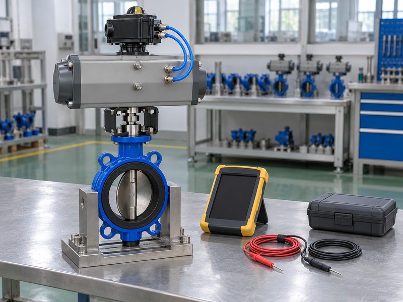
3. How does a butterfly valve with positioner manufacturer check fit?
A butterfly valve with positioner manufacturer checks fit through the valve-drive mounting, positioner bracket and feedback coupling for the actual assembly. Bolt alignment alone cannot verify shaft engagement, travel direction or acceptable loading. Review the complete installation envelope, including disc clearance, pipe interfaces, tubing access and the room needed for adjustment or maintenance.
Which mechanical interfaces need approval?
Match the valve shaft, actuator output and coupling dimensions with the approved drawing. Follow the feedback connection. Check that the positioner’s permitted travel and mounting arrangement fit the actuator, with no binding or lost engagement through the stroke. Your inspection plan should also identify the physical closed position, so a displayed endpoint cannot conceal a misindexed disc or an incorrectly set mechanical stop.
- Approve shaft, bracket and coupling interfaces together.
- Check feedback engagement through the complete stroke.
- Verify disc clearance and the physical endpoint.
Key takeaway: A compatible interface lets the positioner observe the intended shaft movement without hiding mechanical misalignment or lost motion.
| Check | What you should confirm |
|---|---|
| Drive interface | Coupling and mounting suit the actual shafts |
| Feedback | Engagement and permitted travel are checked |
| Installation | Disc movement and service access remain clear |
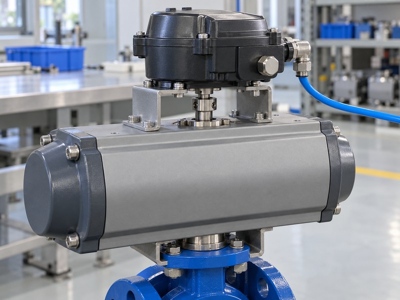
4. Can a butterfly valve with positioner manufacturer prove torque?
A butterfly valve with positioner manufacturer can prove torque suitability by comparing valve demand and available actuator output throughout the required stroke. Use the actual seat, fluid, closing differential pressure, operating frequency and minimum instrument-air supply. Separate valve working pressure, closing differential pressure and inspection pressure when establishing those inputs.
What should the sizing evidence show?
Request the demanded and available torque curves with their conditions and selection basis. Examine the return stroke too. A spring-return assembly needs the relevant spring output and resisting valve torque checked through its specified action, while a double-acting unit needs its own pressure and loading basis. Review coupling and shaft loads alongside actuator output; nominal actuator size cannot settle those questions.
- State the minimum air supply at the assembly.
- Compare torque demand and output over the stroke.
- Review return torque and mechanical load limits.
Key takeaway: Torque approval requires a stated duty and supply condition for the complete movement, including any specified spring return.
| Check | What you should confirm |
|---|---|
| Demand | Actual valve configuration and differential pressure used |
| Output | Minimum supply and stroke position are stated |
| Loads | Shaft, coupling and applicable return conditions checked |
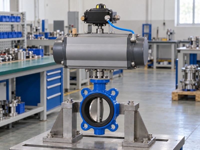
5. What must a butterfly valve with positioner manufacturer connect?
A butterfly valve with positioner manufacturer must connect the specified command, feedback functions and air circuit using the selected component documents. Identify the input type, configured direction, pneumatic variant and output ports. A current input and a position-feedback output serve different functions, even when the project uses similar signal ranges for both.
Which utility details affect approval?
Confirm air pressure, dryness, contamination limits and required capacity against the selected manuals. Check the signal schedule separately. Where the assembly uses a 4–20 mA command, 4 mA normally represents a configured low command and cannot automatically stand for signal failure. Record electrical supply and optional outputs only when the chosen device and supplied accessories support them.
- Freeze input type, direction and supported outputs.
- Identify pneumatic ports and the actual air circuit.
- Use selected manuals for utility requirements.
Key takeaway: Approve an interface schedule and air diagram that describe the supplied devices and their actual configuration.
| Check | What you should confirm |
|---|---|
| Command | Input and configured travel direction are stated |
| Air | Quality, pressure and capacity requirements are identified |
| Outputs | Feedback and accessory functions match supplied devices |
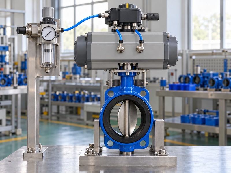
6. How does a butterfly valve with positioner manufacturer set travel?
A butterfly valve with positioner manufacturer sets travel using the selected manual, physical shaft position and agreed calibration procedure. Confirm mechanical mounting and stops before interpreting the displayed range. Calibration can move the valve, so the responsible team must authorize isolation and movement before an automatic adjustment or travel-setting routine starts.
What should sample calibration evidence contain?
Agree the required endpoint, direction and intermediate-position checks before the sample review. Compare indicated and observed movement. Preserve the selected configuration and calibration revision with the assembly ID, including any settings needed to reproduce the accepted function. A completed automatic routine cannot alone verify loaded performance, process response or closed-seat leakage, which need their own acceptance evidence.
- Authorize isolation and movement before calibration starts.
- Verify mechanical direction and the physical travel range.
- Retain settings with the identified assembly revision.
Key takeaway: Travel calibration defines the accepted position range and settings for a mechanically verified, identifiable assembly.
| Check | What you should confirm |
|---|---|
| Preparation | Mounting, stops and movement authorization checked |
| Travel | Indicated positions match observed shaft movement |
| Record | Assembly ID and accepted configuration are preserved |
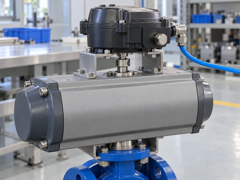
7. What must a butterfly valve with positioner manufacturer test?
A butterfly valve with positioner manufacturer must test the agreed failure events separately from normal command changes. Define air loss, command-signal loss and electrical-power loss, including which other utilities remain available. The proposed action depends on springs, pneumatic porting, selected device functions and accessories, so a single fail-safe label cannot specify every event.
How should you approve the failure-event matrix?
Request the intended action, conditions and acceptance method for each event. Follow the energy path. A springless double-acting actuator has no universal guaranteed endpoint or indefinite hold when supply conditions change; any proposed lockup or stored-air arrangement needs its own definition. Verify the complete assembly under the accepted test conditions, and keep those results distinct from any application safety qualification.
- Define air, signal and power loss separately.
- Identify remaining utilities and any stored energy.
- Verify each required action against agreed conditions.
Key takeaway: Failure approval must describe what the actual assembly does for each specified loss event under stated conditions.
| Check | What you should confirm |
|---|---|
| Event | The failed utility and remaining supplies identified |
| Assembly | Springs, ports and relevant accessories are defined |
| Evidence | Observed action matches the accepted test basis |
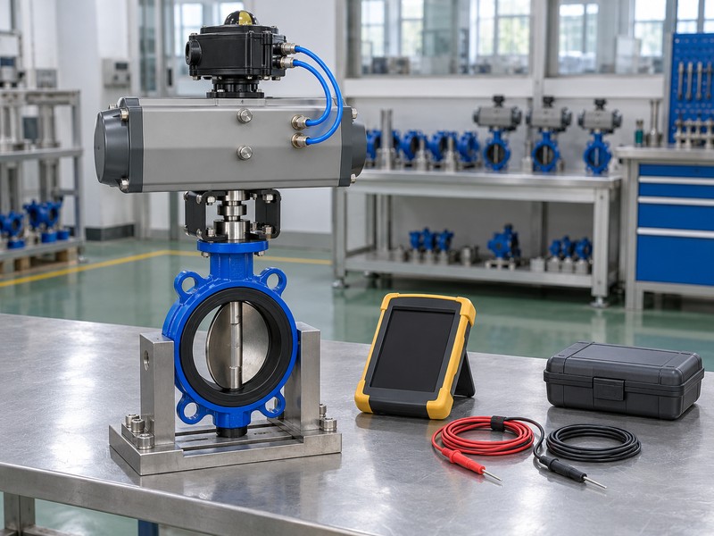
8. Can a butterfly valve with positioner manufacturer prove response?
A butterfly valve with positioner manufacturer can prove response against agreed metrics and recorded test conditions for the selected assembly. Define travel error, repeatability, deadband or response measures only as required by your equipment duty. Compare command and measured shaft position, and distinguish a bench result from movement under the relevant operating load.
What makes a response record reviewable?
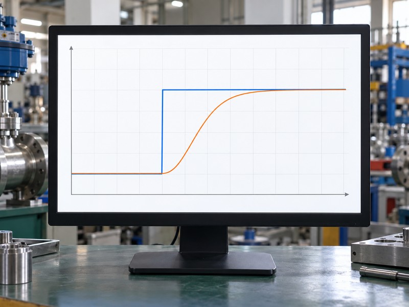
The record should identify assembly revision, command sequence, direction, air conditions, load and measurement method. Read the traces together. Oscillation can involve the command, mechanical feedback, air supply or process response, so tuning needs evidence about the actual cause. The conceptual graph here explains command and shaft-position response; it cannot establish control accuracy or flow performance for a supplied valve.
- Agree performance measures and test conditions before acceptance.
- Record command, travel and relevant supply behaviour.
- Separate bench response from loaded and process results.
Key takeaway: A performance claim becomes reviewable when its metric, conditions and assembly identity accompany the recorded result.
| Check | What you should confirm |
|---|---|
| Metric | Definition and acceptance limit are agreed |
| Conditions | Supply, load, direction and method are recorded |
| Result | Traceable data supports the stated performance scope |
9. What can a butterfly valve with positioner manufacturer approve?
A butterfly valve with positioner manufacturer can support approval within the actual valve duty, accessory scope and evidence reviewed for your project. Confirm fluid compatibility, operating range and any destination requirements for the complete configuration. Adding a positioner cannot extend the valve’s temperature, pressure, material or application limits, or establish an unverified certification.
Which acceptance questions remain separate?
RUITO manages ordinary water, oil, clean-gas and lined duties through distinct valve configurations. Review each acceptance category. Pressure testing under an agreed method such as ISO 5208 addresses the defined integrity and closure scope, while travel response needs separate evidence. a management certificate cannot approve every product or market; verify the exact model, materials, sizes and applicable destination scope.
- Match the valve configuration with the actual service.
- Keep pressure, control and approval evidence distinct.
- Verify product and accessory certification coverage separately.
Key takeaway: Approve only the duty and configuration supported by the relevant engineering, inspection and required qualification evidence.
| Check | What you should confirm |
|---|---|
| Duty | Valve and materials fit accepted service conditions |
| Tests | Integrity and control results retain separate scope |
| Approval | Exact product and destination coverage are checked |
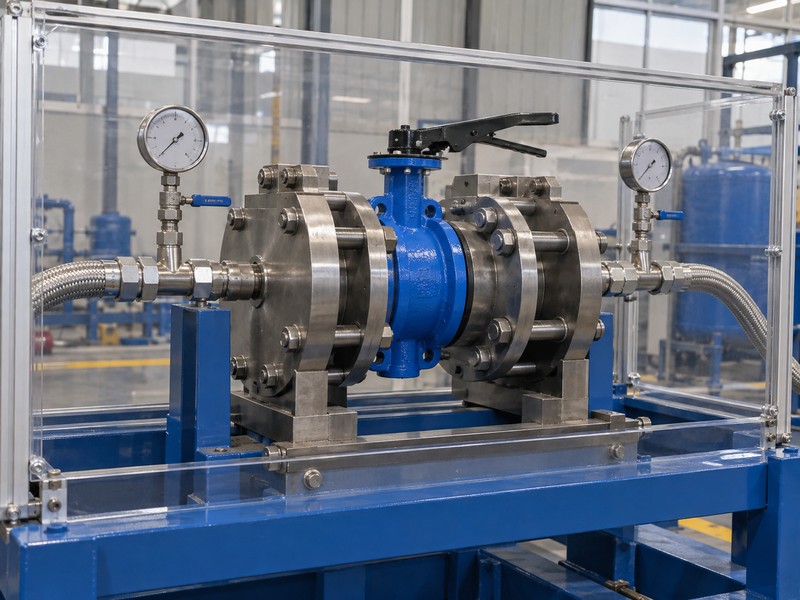
10. Can a butterfly valve with positioner manufacturer repeat orders?
A butterfly valve with positioner manufacturer can repeat an accepted assembly by controlling its component list, drawings, settings and inspection revision. Connect sample approval with the production configuration and delivered IDs. A repeated commercial description cannot preserve an interface or failure action if a positioner variant, coupling, air circuit or seat changes without review.
What belongs in the repeat-order agreement?
Freeze the accepted revision and define which changes need customer authorization before manufacture. Check the effective batch. RUITO uses controlled valve material and drawing definitions; extend the order’s configuration agreement to the selected actuator, positioner and accessories. A change notice should identify the affected function, proposed verification and initial affected products, with spare-part references updated where the change affects maintenance.
- Freeze approved components, settings and inspection requirements.
- Authorize changes before affected assemblies enter production.
- Connect delivered IDs with accepted revisions and spares.
Key takeaway: Repeat supply should reproduce the approved assembly and its documented functions, with changes reviewed before the next batch.
| Check | What you should confirm |
|---|---|
| Baseline | Accepted sample and production definitions match |
| Change | Function, verification and effective products identified |
| Repeat order | Revision and replacement-part references remain traceable |
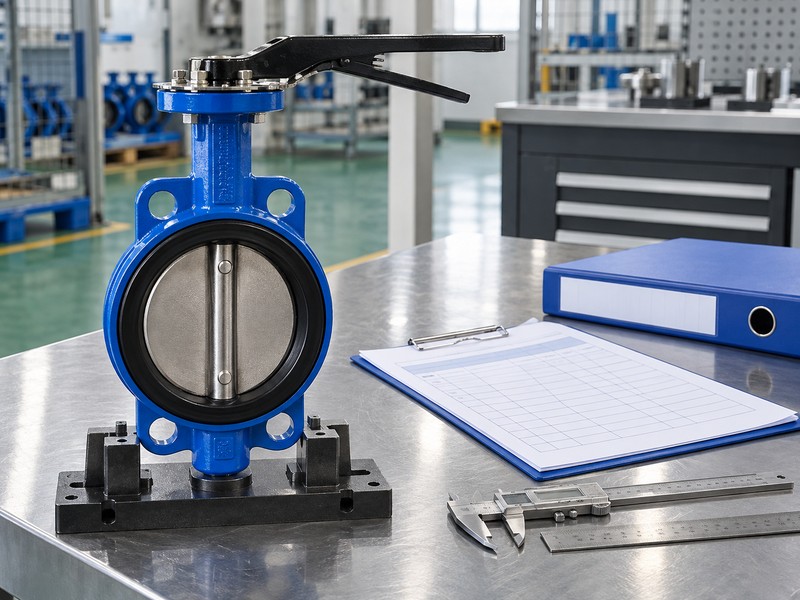
Send RUITO your service sheet, installation envelope, command schedule and required failure actions. We can review the valve duty and identify the assembly documents and verification still needed for approval. Contact us before freezing the sample and repeat-production requirements.
FAQ
Q1: Can I approve the assembly from a positioner datasheet?
No. Review the actual valve, actuator, mounting, air circuit and configured functions together, then agree the evidence required for your operating duty.
Q2: What’s the best way to compare manufacturers?
Use one assembly specification and acceptance plan. Compare identified configurations, deviations and evidence under the same load, supply and operating conditions.
Q3: How do I know if the actuator has enough torque?
Compare demand and output through the stroke. Use actual valve conditions, the declared minimum air supply and any required spring-return action.
Q4: Can I treat 4 mA as a failed signal?
Usually no. It normally represents the configured low command in a 4–20 mA input; confirm the selected device’s separate signal-loss behaviour.
Q5: Can the next batch use an equivalent positioner?
Only after review and approval. Check the variant, mounting, signals, air circuit, settings and failure actions before accepting a substitution.