
Fix fit mistakes by reviewing a wafer type double offset butterfly valve as an identified assembly with separate connection, geometry and duty definitions. Compare its controlled drawing with the actual flanges, pipe bore and selected operating conditions. Confirm the requested construction before transferring dimensions or ratings from another valve configuration.
Matching bolt holes can conceal a disc that strikes the pipe lining or a gasket that conflicts with the seat-retainer arrangement. Those differences can leave an apparently compatible replacement outside its accepted installation limits. Resolve the full interface package before purchasing, with physical work governed by the selected manufacturer’s instructions and the project’s authorized procedures.
1. What defines a wafer type double offset butterfly valve?
A wafer type double offset butterfly valve combines a specified wafer connection with a separately defined double-offset disc-and-shaft geometry. Wafer describes the pipe connection, while double offset describes internal geometry. Neither term establishes the other, and a supplier’s general wafer range cannot verify that the requested combined construction is available.
Which configuration details should the buyer request?
Identify the actual construction. Request the model, body style, seat, size, flange interface and drawing revision as one configuration. Separate concentric-wafer and double-flanged double-offset entries cannot define a combined product. Obtain supplier confirmation and supporting documents before treating that combination as an established purchasing option.
- Identify wafer connection and offset geometry separately.
- Request the actual model and controlled assembly drawing.
- Confirm the proposed configuration before assuming availability.
Key takeaway: Start with one identified construction rather than combining features from separate product descriptions.
| Check | What you should confirm |
|---|---|
| Connection | Selected construction uses the specified wafer interface |
| Geometry | Section drawing identifies the actual double-offset arrangement |
| Supply | Supplier confirms the requested configuration and supporting documents |
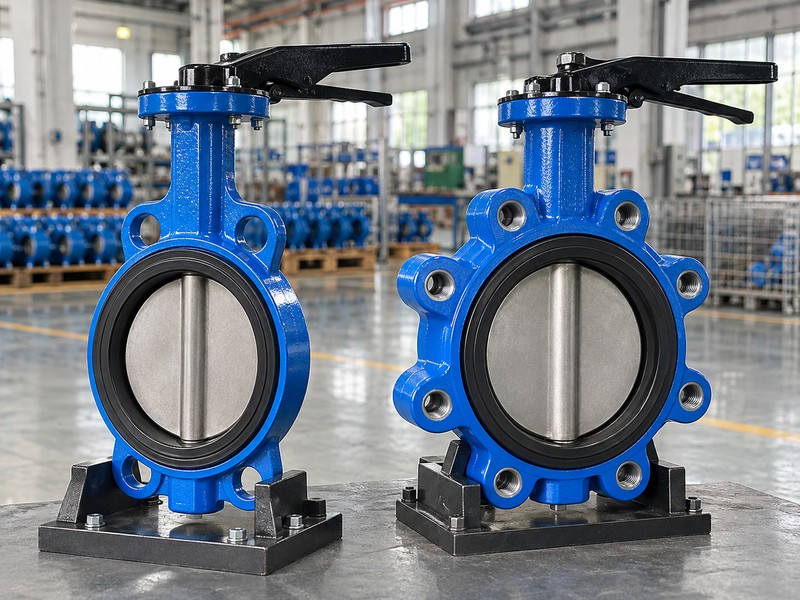
2. How does a wafer type double offset butterfly valve move?
A wafer type double offset butterfly valve rotates its disc about an axis displaced from the seat sealing plane and offset from the bore or seat centerline. The selected section drawing defines those relationships. Cam-like movement can reduce disc-to-seat rubbing during part of travel, while closing still brings the sealing surfaces into contact.
What must the geometry review leave model-specific?
Read the section drawing. The Keystone K-LOK technical sheet illustrates shaft displacement and cam-like operation for its identified family. Use the selected manufacturer’s definitions rather than assigning universal offset distances, release angles or torque reductions. An exterior image cannot establish the internal axis relationships or quantify rubbing, wear or service life.
- Locate the rotation axis through the selected section.
- Read its relationship with the seat plane and centerline.
- Keep movement and performance claims tied to actual product data.
Key takeaway: Use double offset as a geometry definition and verify any claimed performance separately.
| Check | What you should confirm |
|---|---|
| Axis | Section drawing defines the designed shaft location |
| Movement | Disc rotation and seat contact follow the selected design |
| Performance | Any quantified claim has configuration-specific evidence |
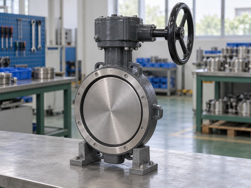
3. What flanges fit a wafer type double offset butterfly valve?
The flanges fitting a wafer type double offset butterfly valve must match its selected flange specification, facing, bolt arrangement and face-to-face length. Nominal DN or NPS alone cannot establish interchangeability. Compare the valve’s actual connection details with both mating flanges and the available installation space.
Which dimensions should remain on the interface checklist?
Compare the mating definitions. Review flange standard and class, facing, bolt pattern, fastener requirements and face-to-face length against the controlled drawing. Retain the specified dimensional standard and edition. A concentric wafer’s length series cannot supply missing dimensions for a different body and seat-retainer arrangement.
- Match actual flange specification, class and facing.
- Review bolting requirements against the selected assembly.
- Compare face-to-face length with the available pipe gap.
Key takeaway: Approve the complete mating interface rather than relying on a nominal size or body-style label.
| Check | What you should confirm |
|---|---|
| Flanges | Both mating interfaces match the selected valve definition |
| Bolting | Pattern and fastener requirements have a controlled basis |
| Length | Actual face-to-face dimension fits the installation review |
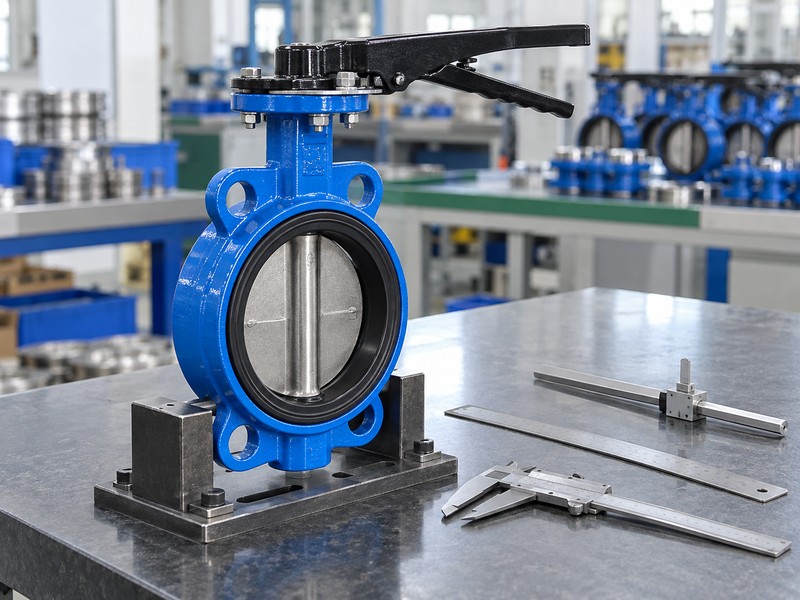
4. Can a wafer type double offset butterfly valve clear the pipe?
A wafer type double offset butterfly valve clears the pipe only when its full disc envelope fits the actual adjoining bores and components. The open disc can project beyond the valve’s body faces. Review pipe inside diameter, lining, nearby reducers and fittings against the selected drawing rather than checking the body opening alone.
How should reviewers check the swept envelope?
Trace the complete disc sweep. The Bray McCannalok installation manual addresses projecting-disc clearance and mating pipe dimensions for its identified family. Review the actual model’s envelope against linings and adjacent restrictions. A nominal pipe schedule or external illustration cannot establish clearance for another design.
- Review disc projection on both sides of the body.
- Compare the full swept envelope with actual adjoining bores.
- Include linings, reducers and nearby fitting restrictions.
Key takeaway: Check moving-disc clearance independently of flange alignment and body fit.
| Check | What you should confirm |
|---|---|
| Envelope | Selected drawing defines the required disc movement space |
| Bore | Actual pipe and lining clear that envelope |
| Adjacent parts | Reducers and fittings preserve the required clearance |
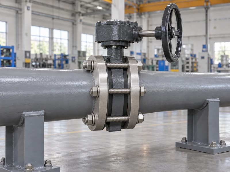
5. What seals a wafer type double offset butterfly valve?
A wafer type double offset butterfly valve has a selected internal seat arrangement and a separately defined pipe-flange sealing interface. Review the seat retainer, body faces and required flange gasket as interacting parts of that construction. A gasket rule from an elastomer-lined concentric valve cannot define the arrangement for every high-performance wafer valve.
Which gasket and retainer details need confirmation?
Check the actual sealing interfaces. Obtain gasket type, dimensions and placement requirements beside the seat-retainer detail. Review support and clearance through the accepted flange assembly; extra bolt load cannot establish compatibility for mismatched parts. The selected instructions govern fasteners, tightening and assembly work, including any construction-specific gasket requirements.
- Identify internal seat and external flange seals separately.
- Review gasket dimensions against body and retainer features.
- Use selected instructions for the actual bolted assembly.
Key takeaway: Review gasket and retainer requirements through the actual construction instead of importing another wafer valve’s rule.
| Check | What you should confirm |
|---|---|
| Seat | Internal sealing arrangement matches the supplied construction |
| Gasket | Specified pipe-flange seal suits the actual mating faces |
| Retainer | Selected assembly preserves the intended retention arrangement |
6. Which way does a wafer type double offset butterfly valve fit?
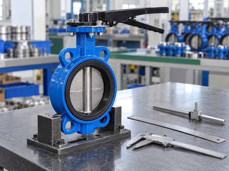
The installation and pressure direction for a wafer type double offset butterfly valve follow the selected model and seat instructions. Preferred orientation, forward and reverse differential limits, and permitted throttling direction are separate questions. A bidirectional sealing statement cannot remove a manufacturer’s preferred mounting orientation or establish equal duty in every operating condition.
What changes when a downstream flange is absent?
Review the stated end condition. Wafer construction alone does not establish end-of-line or dead-end capability. Downstream-flange removal changes restraint and can affect seat retention, requiring explicit support for the actual body, bolting, retention, direction and differential. Record the accepted direction and end condition on the project schedule.
- Record preferred installation and relevant pressure directions.
- Check forward and reverse differential limits separately.
- Request explicit evidence for any proposed end-of-line duty.
Key takeaway: Accept direction and end conditions only within the selected construction’s documented limits.
| Check | What you should confirm |
|---|---|
| Orientation | Selected instructions define the preferred installation arrangement |
| Differential | Permitted duties follow actual direction and seat limits |
| End condition | Restraint and retention have explicit support for the proposed duty |
7. What seat fits a wafer type double offset butterfly valve?
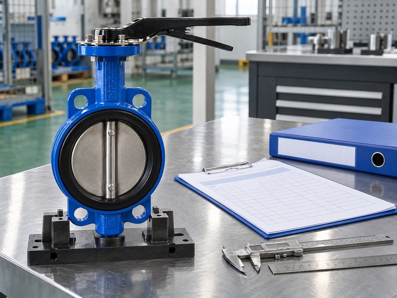
The seat fitting a wafer type double offset butterfly valve must suit the identified fluid, temperature, differential pressure and acceptance requirement. Double-offset geometry does not define one seat material. Polymer, elastomer, metal and combined constructions need their own selected material definitions and applicable sealing-performance evidence.
Which service details belong with the material choice?
Define the actual service. Record fluid composition, contaminants, operating states and cleaning conditions with the proposed seat, disc, shaft and packing materials. A material name or metal-seat description cannot establish a universal leakage class, chemical compatibility or fire-tested configuration. Request the selected leakage method and acceptance criteria, retaining any special option’s actual approval scope rather than extending it to other seats.
- Identify fluid and cleaning conditions for the actual duty.
- Match seat and other relevant materials as one configuration.
- Request applicable leakage criteria and special-option evidence.
Key takeaway: Choose the seat through the complete service and acceptance definition rather than the offset label.
| Check | What you should confirm |
|---|---|
| Service | Fluid and operating conditions are explicitly defined |
| Materials | Selected seat and related components suit that service |
| Acceptance | Leakage and any required approval have identified criteria |
8. What limits a wafer type double offset butterfly valve?
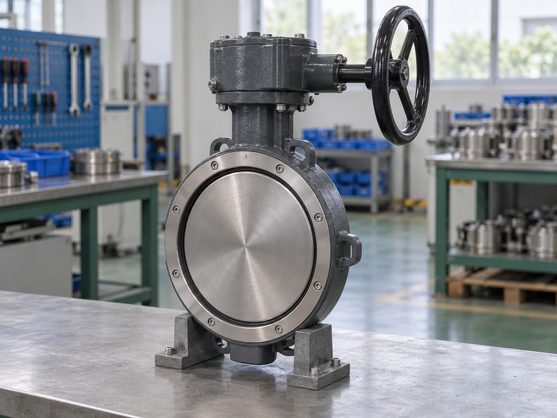
The operating limits of a wafer type double offset butterfly valve belong to the same size and body, disc, shaft, seat and packing configuration. Review its pressure-temperature relationship beside the permitted closing differential. A body pressure class or cold rating cannot establish the seat’s differential capability at the proposed service temperature.
How should the buyer use the pressure-temperature record?
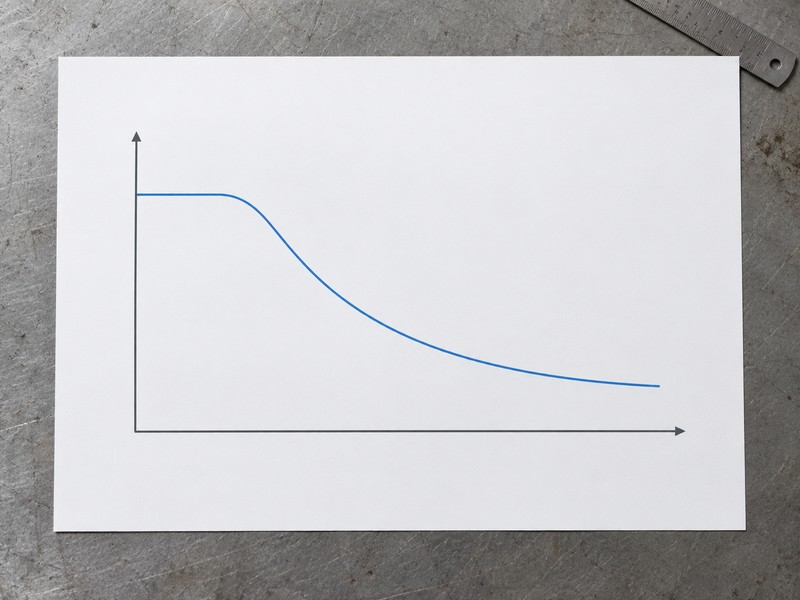
Review each operating condition. Compare normal, shutdown and other specified states with the actual model’s applicable pressure-temperature and differential limits. Do not combine unrelated family maxima or convert a pressure-test condition into an allowable service rating. The conceptual chart illustrates the need for a documented operating envelope; it supplies no numeric rating or shared curve for different materials and seats.
- Keep size and material configuration linked to rating data.
- Check service pressure and closing differential independently.
- Use actual model data for every specified operating state.
Key takeaway: Accept an operating envelope for the identified configuration rather than a family maximum.
| Check | What you should confirm |
|---|---|
| Configuration | All limits belong to the same selected assembly |
| Temperature | Applicable pressure limits cover the stated service condition |
| Differential | Seat and direction limits cover the required shutoff duty |
9. What drives a wafer type double offset butterfly valve?
The operator driving a wafer type double offset butterfly valve must match actual valve demand and permitted drive limits under the stated service. Review seating, unseating, running and relevant fluid torque with the selected operator’s output. A matching mounting pattern cannot establish adequate capacity or acceptable maximum torque through the stem and coupling.
What should the actuator selection record compare?
Trace demand through the drive. Compare valve torque at actual differential and temperature with operator output at its available supply or specified manual input. Check permitted stem, coupling and mounting loads separately. Record the project or manufacturer basis for any allowance; double offset cannot establish a universal factor or smaller-actuator guarantee.
- Request torque demand for the selected seat and service.
- Compare actual operator output with permitted drive limits.
- Record the basis for any applied selection allowance.
Key takeaway: Approve operator selection through both required torque and the complete drive’s allowable limits.
| Check | What you should confirm |
|---|---|
| Demand | Operating torque follows actual valve and service conditions |
| Output | Selected operator meets demand at the stated supply or input |
| Limits | Stem, coupling and mounting remain within permitted loads |
10. What releases a wafer type double offset butterfly valve?
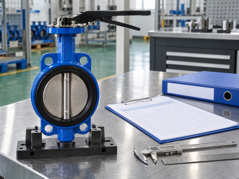
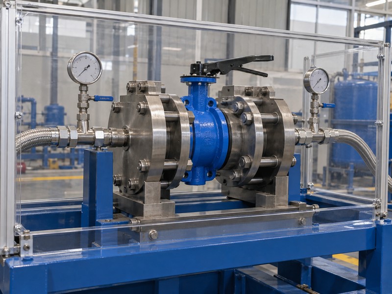
Release a wafer type double offset butterfly valve after its configuration, interfaces, duty and required verification close against accepted documents. Retain the controlled assembly drawing, material schedule, selected manuals and inspection decisions with product identity. An inspection photograph or generic test-fixture image cannot establish that those acceptance requirements have passed.
What should the inspection and handover package retain?
Link records to the actual assembly. The inspection and test plan should identify required dimensional, material, movement and pressure or leakage evidence with acceptance criteria. Retain results, approved deviations and affected rechecks after changes. Destination or service approval requires exact-product evidence rather than a management-system certificate or another manufacturer’s option.
- Link selected drawings and materials with product identity.
- Retain required inspection and test acceptance records.
- Review changed components and preserve approved deviations.
Key takeaway: Release one traceable assembly whose fit, operating duty and required acceptance evidence agree.
| Check | What you should confirm |
|---|---|
| Baseline | Accepted documents identify the requested construction |
| Verification | Required results have a defined acceptance basis |
| Change | Affected interfaces and duties receive renewed review |
Send RUITO your identified valve request, mating flange and pipe details, fluid conditions, required direction and existing drawings. We can review the request and confirm which actual configuration and supporting documents would be needed for evaluation. Contact us before assuming that separately documented wafer and double-offset products establish the combined assembly you need.
FAQ
Q1: Can I replace a concentric wafer valve using nominal size alone?
No. Compare actual flange interfaces, face-to-face length, disc envelope, gasket and retainer arrangement with the selected replacement drawing.
Q2: What’s the best evidence that a valve has double-offset geometry?
Request the selected section drawing. An exterior photograph or wafer connection label cannot establish the internal shaft and seat relationships.
Q3: How do I know if the disc clears a lined pipe?
Review the full swept envelope. Compare actual disc projection with the pipe lining, adjoining bore and nearby fittings using controlled dimensions.
Q4: Can I assume a wafer valve supports end-of-line service?
No. The exact body, retention, bolting, direction and differential need explicit manufacturer support for that duty.
Q5: How do I know if RUITO can support the requested combination?
Request configuration confirmation. The identified wafer double-offset request needs its own reviewed construction and supporting documents before any supply commitment.