
Choose cap screws by the tapped joint's complete specification, including thread, under-head length, engagement, head form and material. Selecting "cap screw sizes for butterfly valves" from pipe diameter alone leaves those details unresolved. A screw can turn freely and still bottom before it clamps the flange, so check the actual joint drawing before ordering a replacement set.
1. Where are cap screws used on butterfly valve assemblies?
Cap screws can fasten a pipe flange to a tapped lug, secure mounting hardware or hold other specified assembly components. Each location has a different load path and may require a different thread or strength specification. A fastener used on an actuator bracket should not be copied into a pressure-boundary joint because its head looks similar. Identify the exact connection and the component receiving the thread before you measure an existing screw.
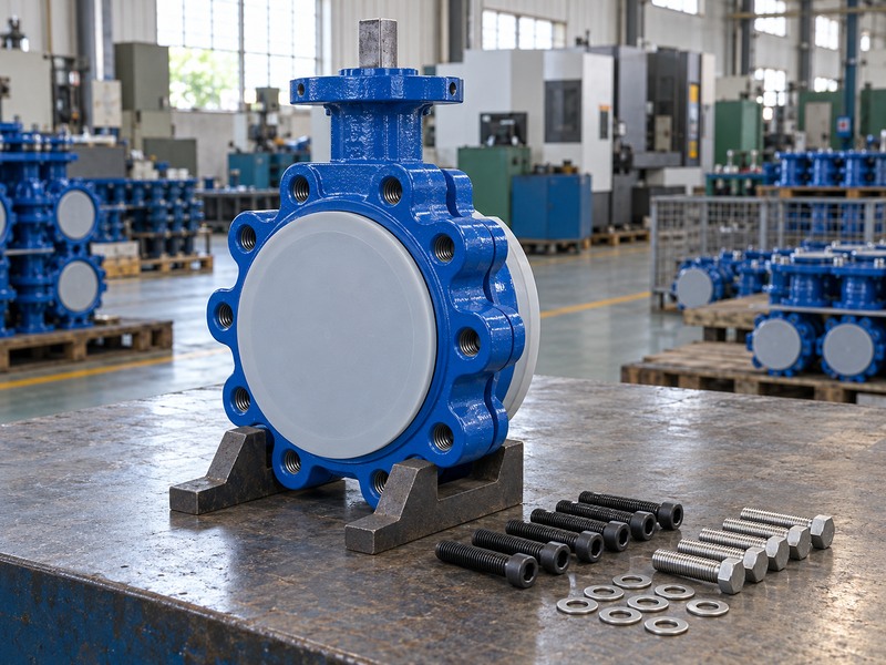
Which fastening arrangement are you reviewing?
Draw the sequence from the screw head through the washer and clamped component into the tapped part. Record whether the threaded hole is blind, continuously open or machined from both sides. A screw entering one side of a lug can meet an opposite fastener before reaching its required engagement. Keep those physical limits visible in the schedule. The phrase 'butterfly valve bolt' is too broad to distinguish this joint from a long wafer through-stud with nuts.
- Identify the receiving tapped component.
- Separate pipe-joint and actuator-mounting fasteners.
- Record blind depth and opposite-side restrictions.
| Location | Connection to identify | Separate review |
|---|---|---|
| Tapped lug | Pipe flange to valve body | Engagement and pressure-joint loading |
| Mounting bracket | Operator support to valve | Torque reaction and stiffness |
| Operator attachment | Actuator to mounting interface | Specified pattern and fastener duty |
2. What does a complete cap screw designation include?
A complete designation identifies thread diameter, pitch or thread series, length convention, head form, material or grade, and any coating. 'M16 bolt' does not state all of those fields. Socket-head and hexagon-head screws also need different tools and head-clearance checks. Establish the intended fastener standard and the joint drawing before comparing commercial listings, because a catalogue's convenient size description may omit details needed for engineering approval.
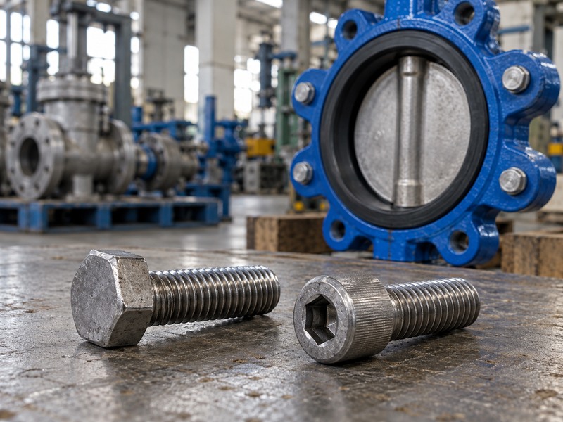
Does a socket-head standard define the whole joint?
ISO 4762 covers hexagon socket head cap screw characteristics within its stated scope. It does not select the screw for your valve's pressure, body material or available engagement. Treat the fastener standard as one part of the purchase specification. The assembly drawing still needs to identify the mating thread, clamped stack and permitted loading. If an alternate head form is proposed, check its bearing surface, socket access and surrounding clearance before treating it as an equivalent item.
- Specify the full thread and length callout.
- Keep head form and tool access visible.
- Confirm grade, coating and matching installation procedure.
| Callout field | What it resolves | Still required |
|---|---|---|
| Diameter and pitch | Mating thread identity | Usable thread depth |
| Length and head form | Physical installation | Engagement and head access |
| Material and coating | Specified fastener condition | Joint-specific load and tightening review |
3. How do you verify diameter and thread pitch?
Verify diameter and pitch independently with suitable instruments, then compare both with the controlled thread specification. A caliper can support a diameter check, while a thread gauge helps identify pitch or threads per inch. Neither observation by itself establishes the required tolerance or usable depth. Inspect the tapped lug as well as the removed screw, particularly when damaged threads or coating buildup may explain why a previous installation felt tight.

Can an old screw establish the required thread?
An old screw is evidence of what was installed, and the installation may have been wrong. Check its marking and condition against the original drawing or a supplier-confirmed replacement specification. Start a confirmed screw only according to the approved assembly procedure; do not use extra torque to force a suspected pitch match. For a lug butterfly valve, damage in a cast boss requires an accepted repair or replacement decision rather than an improvised larger thread cut on site.
- Check the screw and receiving thread.
- Record complete pitch or TPI information.
- Refer damaged bosses for an approved disposition.
| Observation | Useful evidence | Limit |
|---|---|---|
| Outside thread diameter | Nominal size comparison | Does not identify pitch |
| Pitch gauge fit | Thread spacing comparison | Does not establish full thread tolerance |
| Original drawing | Approved thread designation | Must match the supplied revision |
4. How do you calculate the required screw length?
Calculate under-head length from the clamped stack plus the required engagement into the receiving part. The clamped stack includes the actual flange or bracket thickness, specified washers and any other approved elements between the bearing surfaces. Check that the selected screw provides enough usable thread engagement without reaching the blind bottom or an opposite fastener. Thread runout, lead-in chamfers and incomplete tapped threads can reduce the useful engagement below the apparent drilled depth.
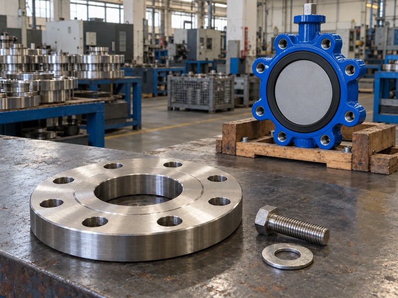
How does a length window help procurement?
Use a minimum and maximum accepted length when the joint permits them. As an illustrative calculation only, assume a drawing specifies a 22 mm clamped stack and accepts 16–22 mm of usable engagement: the corresponding under-head length window is 38–44 mm before any additional drawing allowances. A 40 mm screw would project 18 mm beyond that stack. This arithmetic does not select a real valve fastener; the engineer must first confirm the permitted engagement, runout, strength and bottom clearance.
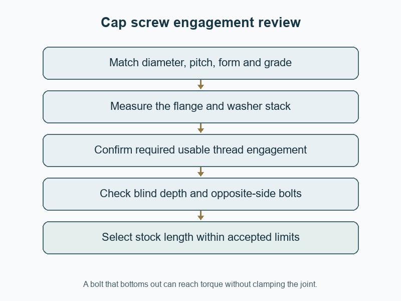
- Measure from the specified under-head bearing face.
- Use usable engagement rather than drilled depth.
- Check the next available stock length against both limits.
| Illustrative term | Assumed value | Derived result |
|---|---|---|
| Clamped stack | 22 mm | Starting reference |
| Accepted engagement | 16–22 mm | Length window 38–44 mm |
| Candidate under-head length | 40 mm | 18 mm projection beyond the stack |
5. Why does usable engagement differ from hole depth?
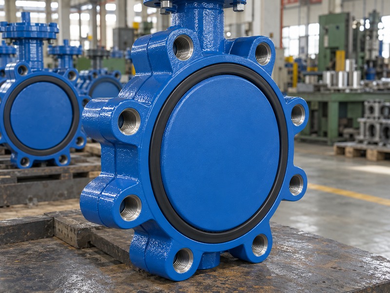
Usable engagement covers the mating full threads that can transmit the required load. A drilled blind hole extends beyond the finished threaded portion, while the entrance chamfer and tap runout can leave incomplete threads. The screw's own end and thread runout also affect contact. Measuring to the deepest point with a depth rod therefore gives an overall cavity dimension, rather than the accepted engaged-thread length that the joint calculation needs.
Can one diameter of engagement be used everywhere?
Do not adopt a universal engagement multiple without the joint designer's approval. Receiving material, fastener strength, thread form, available wall section and the required loading affect the assessment. A rule used for a particular manufacturer's lug design cannot automatically qualify a different cast body or an actuator bracket. Ask for the approved minimum engagement and maximum permitted projection. Keep corrosion allowance, existing damage and repair history in the review when reusing an older valve body.
- Distinguish drilled, tapped and usable depths.
- Account for both male and female incomplete threads.
- Use the accepted engagement requirement for that joint.
| Depth term | What it describes | Selection use |
|---|---|---|
| Drilled depth | Total prepared cavity | Bottom-clearance context |
| Tapped depth | Extent of the tapping operation | Thread inspection context |
| Usable engagement | Accepted full mating threads | Load and length review |
6. What head and tool clearances must you reserve?
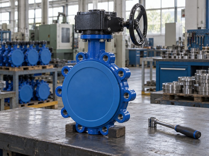
Reserve space for the screw head, its specified washer and the tool needed to tighten and remove it. A socket-head screw needs suitable axial access for its key or driver, while a hexagon head needs room for a socket or wrench. Check the body neck, nearby ribs, gearbox and pipe flange profile. A correctly sized thread does not make a fastener installable if the tool cannot reach it after the assembly is positioned.
Should the assembly sequence change the schedule?
Review the valve with the selected operator and surrounding pipework in place. A screw may be accessible before the bracket is mounted but trapped afterward, making later maintenance difficult. For a wafer butterfly valve with special blind fasteners near the neck, obtain the position-specific arrangement rather than assuming every location accepts the same head. Any proposed change in head height, washer form or tool approach needs the joint designer's acceptance because it can alter bearing and load distribution.
- Check installation and later removal access.
- Include the complete operator envelope.
- Approve alternate head forms before purchasing.
| Clearance | Check against | Possible problem |
|---|---|---|
| Head envelope | Neck, ribs and flange profile | Physical interference |
| Tool approach | Socket or driver geometry | Unable to apply the specified procedure |
| Removal path | Installed operator and pipework | Fastener trapped during maintenance |
7. How do material and coating affect the choice?
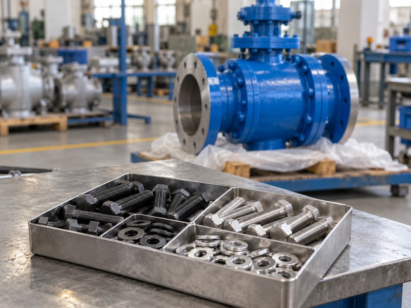
Material, strength grade and coating affect fastener capacity, corrosion behavior and tightening conditions. A screw's dimensions do not establish those properties. The receiving lug or bracket can also limit the load before the screw reaches its own capacity. Match the specified fastener and surrounding materials to the service environment, including temperature and external chemical exposure, rather than choosing a replacement solely because a stainless finish appears more corrosion resistant.
Which substitutions need engineering review?
Review changes in material grade, coating, lubrication, washer type or head bearing area against the accepted joint design. These changes can alter friction, preload and local contact stresses. A higher grade does not authorize higher tightening torque, and a larger washer cannot be added automatically to a crowded bearing surface. For a flanged butterfly valve assembly, consider the mating flange's limitations and the valve's sealing arrangement alongside the proposed fastener. Keep the exact substitution in the purchase record.
- Specify material and strength independently of size.
- Retain coating and lubrication assumptions.
- Check the receiving component and bearing surface limits.
| Change | Why it affects the joint | Required response |
|---|---|---|
| Material or grade | Changes capacity and environment suitability | Engineering acceptance |
| Coating or lubrication | Changes tightening friction | Procedure review |
| Head or washer | Changes contact and clearance | Bearing and access review |
8. How do you prevent a bottomed screw from passing inspection?
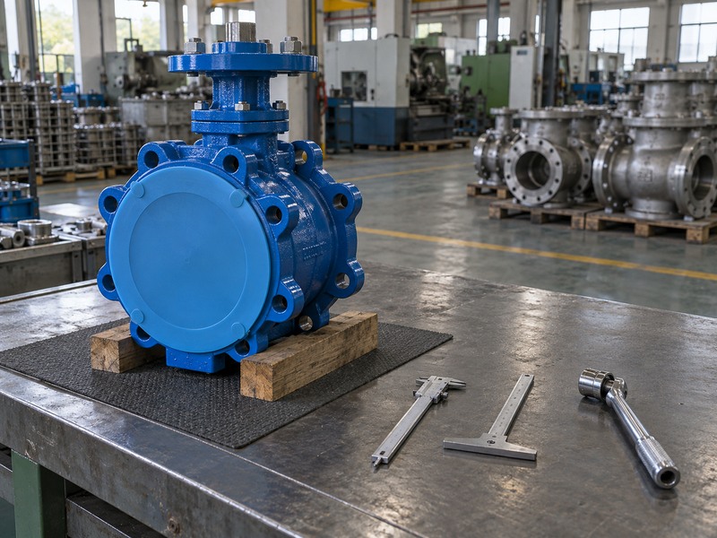
Prevent false acceptance by checking engagement and bottom clearance before relying on applied torque. A screw can contact the bottom of a blind hole and produce tool resistance while leaving the flange insufficiently clamped. Opposing screws can create a similar problem in a lug. Confirm the installed length, clamped stack and usable space, then follow the approved tightening and inspection procedure for the complete joint.
What should an installer record?
Record the specified fastener identification and location, the agreed surface condition and the required tightening checks. Do not infer adequate clamping from an isolated wrench reading. If the joint leaks, investigate the seal, alignment, engagement and fastener condition before increasing torque. An added washer or cut-down screw may change the symptom while leaving the original design question unresolved. Refer any field modification to the responsible engineer and retain the approved disposition with the assembly record.
- Check the length and bottom clearance before assembly.
- Verify the actual bearing and clamping condition.
- Control field changes to screws, washers and tapped parts.
| Check | What it can reveal | Why torque alone misses it |
|---|---|---|
| Projection and depth | Bottoming or opposite-side contact | Resistance can arise without clamping |
| Bearing condition | Head or washer interference | Load may enter the wrong surface |
| Joint inspection | Alignment or seal error | More load may worsen the fault |
9. What belongs in an approved cap screw schedule?
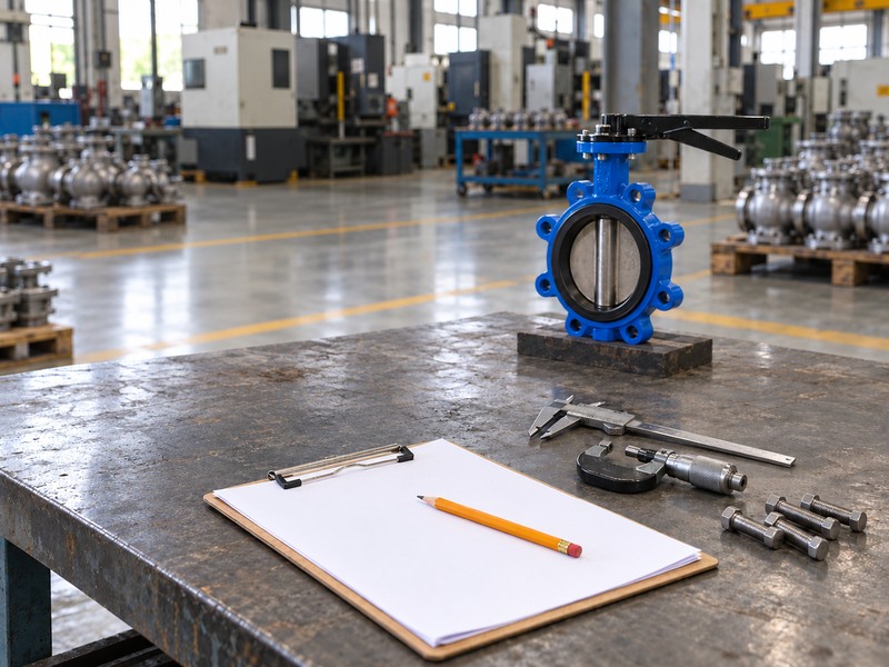
An approved schedule identifies each location, screw standard, complete thread, under-head length, grade, coating, washer arrangement and quantity. Link the schedule to the valve and mounting drawings so procurement and assembly use the same revision. Where different lengths or head forms appear around the circumference, show their positions explicitly. A single line saying 'M16 valve bolts' cannot communicate the geometry and installation assumptions needed for a reviewable order.
How should you request a replacement set?
For RUITO enquiries, contact us with the valve identification, mating flange or bracket drawing, existing fastener details and any available depth measurements. State which observations were physically checked and which came from older documents. Ask the supplier to confirm engagement, blind-hole limits and neck-area exceptions before accepting the set. Inspect delivered markings, dimensions and quantities against the accepted schedule, then resolve a substitute or damaged thread before the installation team starts tightening the joint.
- Map each distinct screw to its assembly position.
- Retain the accepted engagement and clearance basis.
- Verify the delivered set before installation.
| Schedule item | Required detail | Review purpose |
|---|---|---|
| Identity | Standard, thread and grade | Correct component ordered |
| Geometry | Length, head and washer | Fit and usable engagement |
| Position and quantity | Location sketch and count | Complete installable set |
10. What questions arise when choosing valve cap screws?
Q1. Can I choose cap screw length from DN alone?
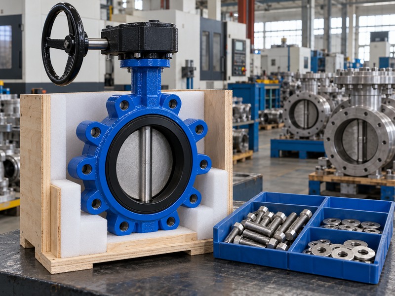
No. Length depends on the actual clamped stack, usable tapped engagement, head convention and available clearance. Use the exact joint drawing and confirm special positions near the valve neck or operator.
Q2. How do I know whether a screw has bottomed out?
Check the installed projection against the usable cavity and opposite-side restrictions. Tool resistance alone cannot prove clamping. Follow the approved inspection procedure and stop if the head or flange does not seat as intended.
Q3. Can I add washers to make a long screw fit?
Only with an approved joint change. Added washers affect bearing, access and the clamped stack, and they may hide an incorrect screw schedule. Obtain the intended stock length or a reviewed alternative.
Q4. What's the best engagement length for a cast lug?
Use the value accepted for that exact joint. Material strength, thread form, fastener grade, wall section and loading all affect the requirement. A generic multiple of screw diameter does not qualify every valve body.
Q5. Can I replace a hexagon-head screw with a socket-head screw?
Only after checking the specified fastener standard, grade, bearing area and tool clearance. Matching thread and length leave those differences unresolved. Record the accepted substitution on the assembly schedule.