
Large butterfly valves need a coordinated review of hydraulic duty, physical envelope, drive loads and installation support. For "large size butterfly valves", a matching DN and flange pattern leave many of those decisions open. Confirm the complete assembly drawing and service cases before the civil opening, lifting plan or pipework layout becomes difficult to change.
1. What counts as large size butterfly valves?
The term 'large' depends on the product family and project context rather than a universal nominal-size threshold. A diameter that is routine for a water transmission main may be unusually large for an equipment skid. State the actual DN or NPS, body construction and connection instead of relying on the adjective. Those details let the supplier identify the proposed design and the site team plan its space, handling and service requirements.
Which product range applies to the enquiry?
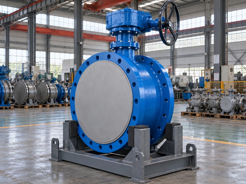
RUITO's supplied business data lists double-offset double-flanged butterfly valves at DN350–3000 and concentric water-service double-flanged valves at DN50–600. These are separate construction ranges with their own configuration limits. Do not combine the largest diameter from one range with another range's materials or service conditions. Ask the supplier to confirm the exact size, pressure designation, seat, operator and directional shutoff requirements for the current enquiry before describing the package as available for the project.
- State actual nominal size and construction.
- Keep product-family ranges separate.
- Confirm current availability for the complete requested configuration.
| Description | What to add | Why it helps |
|---|---|---|
| Large butterfly valve | Exact DN or NPS | Defines the enquiry size |
| Double-flanged | Concentric or double-offset construction | Identifies the drawing family |
| Project configuration | Materials, ratings and drive | Creates a reviewable supply request |
2. How do you select the nominal size for the duty?
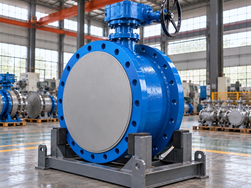
Select nominal size by checking required flow, allowed pressure loss and the intended operating function alongside the pipework arrangement. A line-sized isolation valve still needs model-specific capacity confirmation. A valve used for modulation needs additional review across minimum, normal and maximum flow cases. Choosing the largest diameter that fits the pipe does not establish useful control range, while choosing a smaller diameter introduces reducers, velocity changes and another clearance review.
Which operating cases belong in the calculation?
Provide fluid composition, temperature, density, viscosity, solids and paired upstream and downstream pressure cases. State whether the valve normally stays open, closes under flow or modulates repeatedly. Request the selected model's Cv or Kv data by opening and the applicable hydraulic limits. A full-open coefficient cannot establish performance at every intermediate position. Keep the installation dimensions and hydraulic calculation linked to the same disc, seat and body configuration so a later design substitution does not invalidate the review.
- Separate isolation and continuous modulation duties.
- Pair flow and pressure for each operating case.
- Use the proposed model's capacity and operating limits.
| Duty | Required review | Insufficient shortcut |
|---|---|---|
| Normally open isolation | Flow loss and closing duty | Pipe DN alone |
| Flow modulation | Travel range and hydraulic limits | Full-open capacity alone |
| Size reduction | Velocity, reducers and clearance | A smaller catalogue envelope |
3. Which pressure limits need separate confirmation?
Confirm body pressure at temperature, closed-disc differential pressure and the permitted pressure direction separately. A large valve can have different directional shutoff limits even when the body and flanges carry a familiar pressure designation. Include vacuum, transient pressure and reverse-pressure cases where the system can create them. The accepted service envelope must apply to the same supplied materials, seat, size and operator arrangement, rather than combining maximum figures from different catalogue rows.
What does a factory pressure test establish?
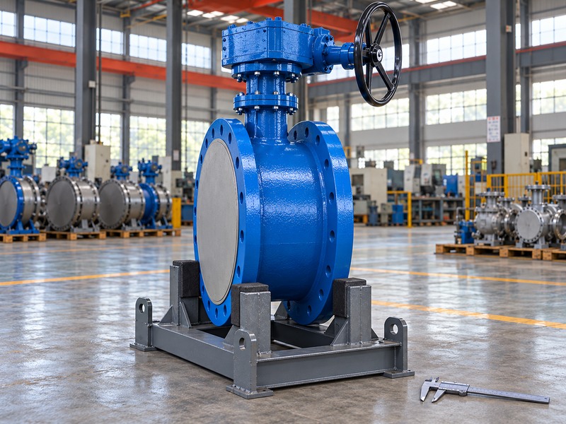
A shell or closure test verifies a specified acceptance condition under an agreed procedure. Its pressure, temperature, medium, direction, duration and acceptance criteria need to match the order. ISO 5208 addresses industrial valve pressure testing; a recorded test result does not raise the valve's working rating. Obtain the proposed pressure-temperature limits and direction-specific closure data alongside the inspection plan. Do not infer a bidirectional service capability from a photograph of a test fixture or gauge.
- Record body and shutoff limits separately.
- Include reverse-pressure and transient cases.
- Keep test conditions separate from operating ratings.
| Limit | What it describes | Evidence to request |
|---|---|---|
| Body pressure at temperature | Pressure-boundary service limit | Configuration-specific rating |
| Shutoff differential | Load across the closed disc | Direction-specific declared limit |
| Test pressure | Inspection condition | Agreed procedure and traceable report |
4. Which drawings establish the complete installation envelope?
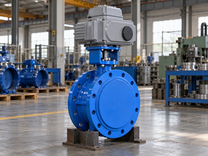
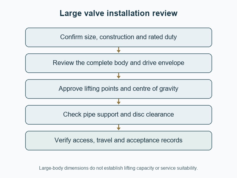
Use the complete assembly drawing to establish body length, flange dimensions, disc travel, operator envelope and maintenance access. Large castings, brackets and handwheels can occupy space beyond the pipe flange outline. The installation also needs room to insert fasteners and withdraw the valve later. A bare-body height or a generic size chart cannot confirm whether the assembled package will pass through the building opening or fit inside the intended valve chamber.
How should the dimensional review be coordinated?
Compare the supplier drawing with the actual civil, pipe and support layout. Check the mating flange bore, face condition, drilling and specified sealing arrangement on both sides. For a double-flanged butterfly valve, identify the exact face-to-face series and any special flange details rather than transferring dimensions from a wafer chart. Record transport width and height separately from installed dimensions if removable components change the envelope, and define who is responsible for reassembly and verification at site.
- Review the valve with its selected drive fitted.
- Include installation and withdrawal space.
- Control transport and final assembly configurations separately.
| Envelope | Check against | Possible consequence |
|---|---|---|
| Installed assembly | Pipework and civil layout | Interference with walls or equipment |
| Maintenance access | Tool and withdrawal paths | Unable to service or remove the unit |
| Transport package | Doors, route and lifting space | Delivery or positioning obstruction |
5. How do you match the drive to a large valve?
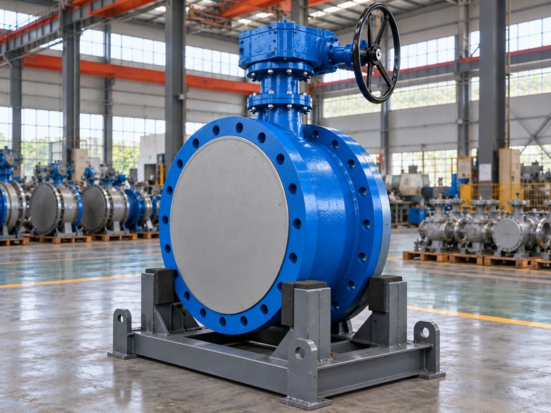
Match the drive to the valve's required torque throughout travel under the stated service cases. Include unseating, running and seating conditions, pressure direction and the required response to loss of power or air. The operator must provide the agreed margin while respecting the allowable transmitted torque of the shaft, coupling and mounting hardware. A large output rating by itself cannot establish suitability, particularly when torque varies with opening or supply conditions.
What additional loads enter the mounting review?
Review actuator weight, centre of gravity, bracket stiffness and reaction loads alongside transmitted torque. A large electric actuator mounted high above the valve may need a support arrangement accepted by the assembly designer. Include manual override access, operating speed and any cycle-frequency limits. Confirm whether the quoted torque data covers the actual seat, temperature and shutoff differential. If the proposed drive changes after approval, recheck both the mechanical interface and the external loads rather than accepting it as a simple accessory substitution.
- Compare complete torque requirements and output curves.
- Check maximum transmitted torque as well as minimum output.
- Review weight and reaction loads in the full mounting assembly.
| Drive check | Input | Acceptance question |
|---|---|---|
| Required output | Valve torque by travel and duty | Can it complete every required stroke? |
| Mechanical limit | Shaft, coupling and bracket capacity | Can the assembly tolerate peak output? |
| External loading | Drive mass and orientation | Is the mounting and support arrangement accepted? |
6. What information belongs in the handling plan?
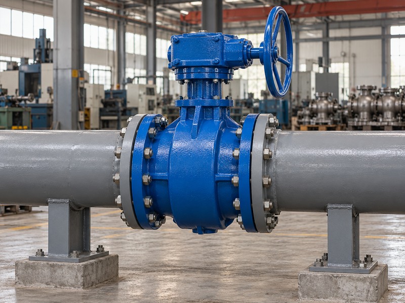
The handling plan needs the actual shipped mass, centre of gravity, approved lifting points and transport configuration. Obtain these details for the supplied assembly, including the drive and accessories when fitted. A body size or flange diameter cannot establish the lifting load. Avoid treating a gearbox, handwheel, actuator or unverified casting feature as a lifting point merely because it is convenient to reach during unloading.
How should the supplier and site share responsibilities?
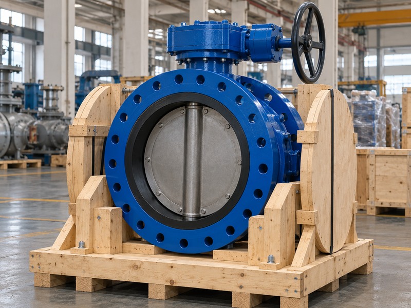
Ask the supplier to identify approved support and restraint locations on the packing or handling drawing. The site team then selects the appropriate equipment and procedure for the route and lifting conditions. Review any requirement to remove the drive or change orientation before delivery. Protect end faces, linings and exposed drive parts while keeping the load supported through accepted locations. Record what must be inspected after transport so a shifted support or damaged cover does not disappear into the installation process.
- Use mass and centre-of-gravity data for the shipped configuration.
- Confirm lifting and restraint points before unloading.
- Protect seals and machined faces without loading the operator.
| Handling input | Source to request | Purpose |
|---|---|---|
| Mass and centre of gravity | Supplier's shipped-assembly data | Equipment and balance planning |
| Lifting and support points | Approved handling drawing | Controlled load path |
| Transport protection | Packing and restraint detail | Prevent damage before installation |
7. How do pipe supports and transient conditions affect fit?
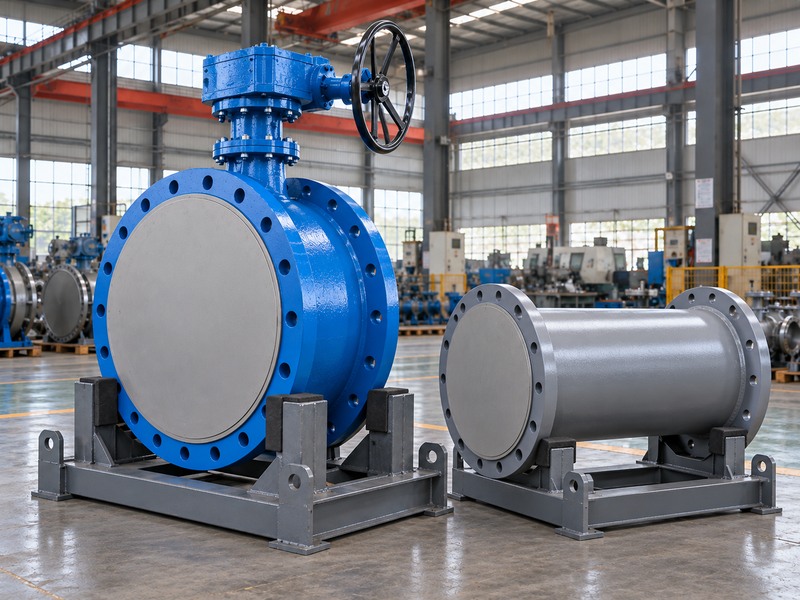
Pipe supports and transient conditions affect the loads that reach the valve and its joints. A geometrically aligned flange pair can still impose unacceptable bending or displacement when piping is unsupported, thermally moving or poorly restrained. Large valves need a coordinated system layout rather than an assumption that the valve body or operator can carry nearby pipe weight. Review the accepted support and restraint arrangement with the responsible piping engineer.
Which clearances and operating conditions remain connected?
Check the swept-disc envelope against pipe bores, reducers and adjacent equipment while reviewing the support layout. A change in spool position can alter both mechanical loading and disc clearance. Closing time also interacts with the hydraulic system; avoid choosing speed solely for operator convenience when surge or reverse-flow scenarios govern. RUITO's water and wastewater applications require configuration-specific fluid and duty review, including solids and fibres that may obstruct the disc rather than assuming every water-service valve suits untreated wastewater.
- Support the adjacent piping independently as designed.
- Review movement, restraint and alignment together.
- Agree closing time with the system's transient requirements.
| System feature | Review question | Risk to address |
|---|---|---|
| Pipe supports | Where do weight and movement loads go? | Flange distortion or misalignment |
| Adjacent bore | Does the complete disc envelope clear? | Physical interference |
| Closing behavior | Does the system permit the chosen speed? | Surge or uncontrolled reverse-flow effects |
8. Which inspection records support acceptance?
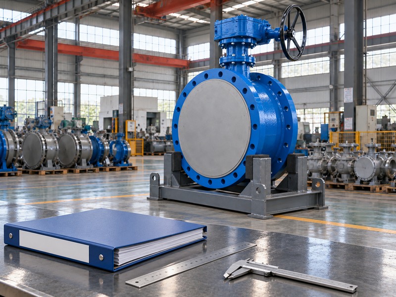
Acceptance should use records that identify the actual supplied assembly and the agreed inspection criteria. Request the approved drawing, material list, pressure and closure results, dimensional checks and operating verification specified by the order. Large-body size does not make a test report more persuasive unless its identity and procedure can be traced. A clean factory photograph can illustrate the product but cannot establish the dimensions, material grade or test conditions of the unit being delivered.
How do you keep the evidence connected?
Link the serial or product identification to the drawing revision, material records and inspection results. Confirm which checks apply to every supplied unit and which are type or representative tests. If a lined construction is proposed, include the agreed lining integrity and dimensional checks rather than transferring acceptance from an ordinary water-service design. Review open deviations before release, then retain the accepted configuration in the maintenance record so future spares and drive replacements can be matched to the installed unit.
- Match reports to product identification and revision.
- Distinguish unit tests from representative qualification evidence.
- Close material, dimensional and functional deviations before release.
| Evidence | What to match | Acceptance use |
|---|---|---|
| Drawing and dimensions | Supplied body and drive revision | Installation fit |
| Material and pressure records | Product identity and procedure | Specified configuration and inspection |
| Functional checks | Travel, drive and feedback arrangement | Agreed operating behavior |
9. How should you prepare the large-valve RFQ?
Prepare the RFQ around the complete service and installation case. Include nominal size, construction, connection, fluid, temperature, pressure cases, operating function, drive supply, closing-time requirements and available space. Add required documents, inspection hold points, packing and delivery constraints. This gives engineering and procurement a shared basis for comparing offers instead of treating two large valves with the same DN as equivalent packages.
What should the quotation return for approval?
Ask for the proposed configuration, marked drawings, rating and torque data, shipped mass and a clear deviation list. For RUITO enquiries, contact us with the duty sheet and installation layout so engineering can identify the evidence needed for the proposed assembly. Keep civil openings, lifting access and support responsibilities visible before production release. When the accepted operator or body changes, update the affected drawings and handling data before confirming the delivery arrangement.
- Send service data and layout together.
- Compare complete assemblies and declared deviations.
- Keep handling and installation responsibilities in the order.
| RFQ section | Include | Supplier response |
|---|---|---|
| Service | Paired operating and limiting cases | Proposed configuration and limits |
| Installation | Interfaces, envelope and support layout | Marked assembly drawing |
| Delivery and acceptance | Handling, packing and inspection needs | Mass, documents and release plan |
10. What questions arise when buying large butterfly valves?
Q1. Can I define a large valve by one universal DN threshold?
No. The description varies by product family and application. Specify the actual DN or NPS, construction and connection so the supplier and installation team can review a definite assembly.
Q2. How do I know whether the valve seals in both directions?
Obtain the direction-specific shutoff limits for the exact configuration. A body pressure designation or matching flange pattern does not establish the same closure differential in both directions.
Q3. Can I lift the assembly by its gearbox?
Use only the lifting points and procedure approved for the supplied assembly. Obtain its mass and centre of gravity, then have the site handling plan matched to those data. Operator housings and handwheels are not assumed lifting points.
Q4. What's the best operator for a large valve?
Select it from the required torque, speed, available supply and loss-of-energy response. Check mechanical limits, external loads and maintenance access as part of the complete assembly review.
Q5. Can a large valve carry the adjoining pipe weight?
Only loads accepted by the responsible design review may be applied. Provide the intended pipe support and restraint arrangement. Geometric fit alone cannot establish acceptable body, flange or operator loading.