
Fix pneumatic butterfly valve sizing mistakes by checking torque throughout both strokes at minimum dynamic air pressure. A pneumatic high performance butterfly valve also needs the right seat, materials and pipe interfaces. If your valve stalls during shutdown, match the complete assembly against a documented operating case before ordering a replacement.
1. What is a pneumatic high performance butterfly valve?
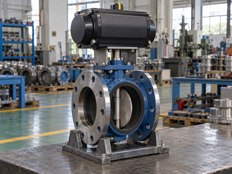
A pneumatic high performance butterfly valve uses a defined seat and disc design with pneumatic actuation; the description alone gives you no pressure or temperature rating. In industrial purchasing, high performance often refers to double-offset designs. Confirm the actual section drawing because a large actuator or stainless disc doesn’t establish offset geometry. The actuator supplies motion while the valve body, seat and shaft contain and control the process fluid.
Which duty are you specifying?
Start with the required function. An isolation valve must close against the stated differential pressure. A control valve must also operate across the expected flow range without unacceptable vibration, noise or seat damage. A vendor’s tight-shutoff statement needs a test method, direction, medium and acceptance limit. Ask whether that limit applies at operating temperature or only during an ambient test. Record those answers beside the selected butterfly valve configuration so purchasing and commissioning use the same basis.
- State isolation or control duty.
- Separate process pressure from actuator air pressure.
- Record the permitted flow and closure direction.
| Item | Confirm before selection |
|---|---|
| Geometry | Section drawing and seat arrangement |
| Rating | Model-specific pressure–temperature limits |
| Drive | Minimum dynamic air pressure |
Use the drawing to resolve any difference between a marketing name and the offered construction.
2. How do body, disc and seat affect shutoff?
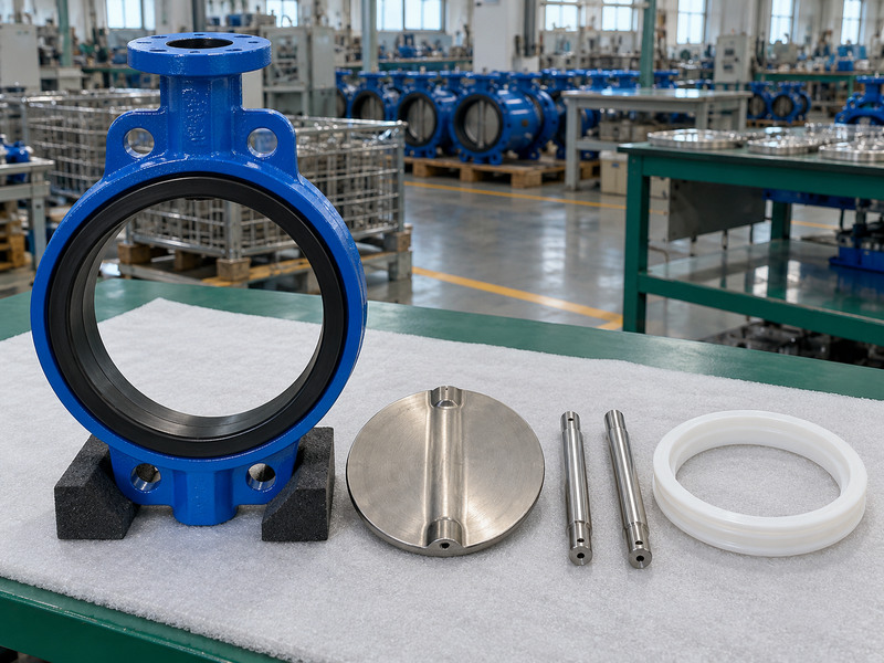
A pneumatic high performance butterfly valve achieves shutoff through its complete sealing assembly, including the disc edge, seat, shaft support and retention details. Double-offset geometry moves the shaft relative to the bore and sealing plane. It reduces rubbing over part of the stroke, but the seat still has a specified contact pattern and closure requirement. A metal seat, polymer seat and elastomer liner require different inspection and maintenance decisions.
What should the drawing show?
Ask for wetted materials, seat retention, shaft bearings and the allowed pressure direction. A generic material list can miss the seat backing or auxiliary seals that limit chemical compatibility. A replaceable seat also needs an approved procedure and spare-part identity. Reusing a similar-looking ring can change compression, operating torque or leakage. If a vendor proposes a different seal during production, request an engineering review before accepting the substitution.
- Check disc edge condition and seat retention.
- Identify every process-contact seal.
- Keep replacement parts tied to the approved assembly.
| Construction detail | Purchasing question |
|---|---|
| Seat backing | Does it limit temperature or vacuum duty? |
| Shaft support | How are radial and axial loads carried? |
| Disc seal contact | What closure torque and direction apply? |
Photographs help identify parts; drawings and test records establish their suitability.
3. How much actuator torque is enough?

A pneumatic high performance butterfly valve needs actuator output above its required torque throughout both operating strokes. Compare breakaway, running and seating requirements with available actuator torque at minimum dynamic air pressure. A single catalogue maximum can hide an inadequate endpoint. For spring-return assemblies, check both the air stroke and spring stroke because their output curves differ.
How should you check the margin?
Use the valve maker’s torque data for the exact seat, temperature and differential pressure. As a hypothetical calculation, 120 N·m required torque with an approved factor of 1.3 gives 156 N·m. An actuator offering 170 N·m at that same position and minimum air pressure clears that point only. You still need the remaining stroke points and the allowable shaft and mounting loads. A larger actuator can overload the valve if its maximum output exceeds those limits.
- Use dynamic pressure measured during travel.
- Check both directions at relevant positions.
- Compare maximum output with allowable stem torque.
| Illustrative input | Value |
|---|---|
| Required torque at one position | 120 N·m |
| Project-approved factor | 1.3 |
| Minimum output at that position | 156 N·m |
The accompanying unscaled chart explains curve comparison; request actual curves for sizing.
4. Why can mounting hardware cause a stall?
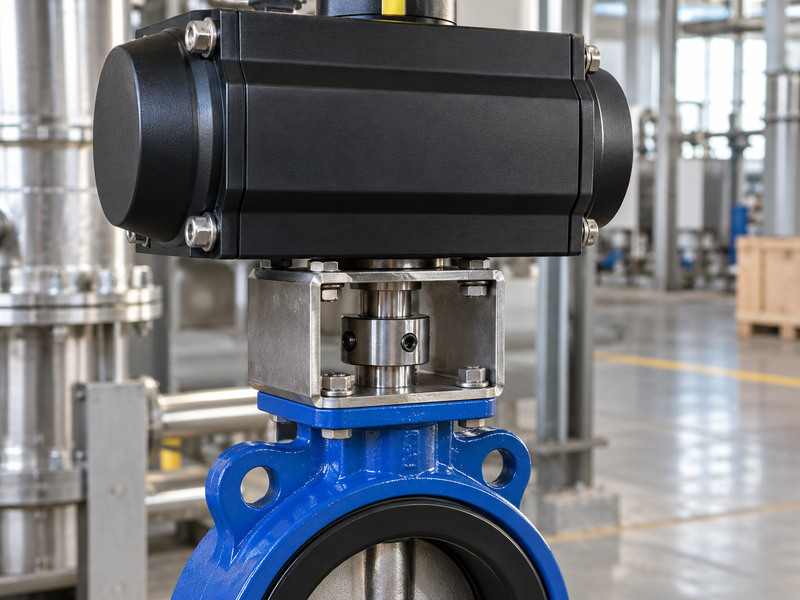
A pneumatic high performance butterfly valve can stall when a misaligned coupling loads the shaft sideways, even if the actuator has adequate output. The mounting pad, bracket and coupling must form a compatible assembly. Matching a bolt pattern doesn’t establish shaft engagement, coupling clearance or load capacity. Check the installed stack height and the location of both mechanical stops.
What should you inspect before cycling?
Compare the actuator output and valve shaft dimensions with the assembly drawing and the agreed ISO 5211 attachment requirements. Check engagement length, key or square fit, bracket stiffness and fastener requirements. A coupling must transfer torque without forcing the valve shaft axially. Verify that actuator stops permit the valve’s specified seating position without driving beyond its allowed travel. If an assembly needs a manual override, include its disengagement and interlock requirements in the procedure. Commission with the manufacturer-approved sequence rather than adjusting stops until leakage disappears.
- Verify coaxial alignment and engagement.
- Check bracket and fastener ratings.
- Confirm travel stops against the valve procedure.
| Interface | Evidence required |
|---|---|
| Mounting pad | Approved dimensions and fasteners |
| Coupling | Engagement and torque capacity |
| Stops | Allowed opening and seating positions |
Resolve mechanical binding before increasing air pressure.
5. Which materials suit your actual fluid?
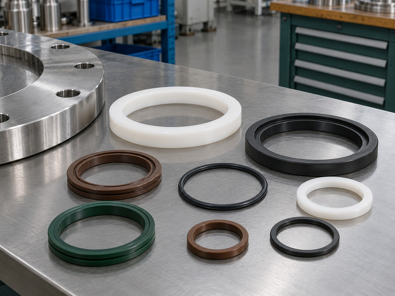
A pneumatic high performance butterfly valve needs a material review for the complete fluid composition and operating envelope. Chemical name alone is insufficient. Concentration, contaminants, cleaning agents, temperature and exposure time can change the choice. Ordinary water-service EPDM cannot be carried across to mineral oil duty without a separate compatibility assessment.
Where do lining claims need closer inspection?
Distinguish a polymer seat from a fully lined wetted flow path. An exposed disc or shaft may remain vulnerable even when the seat resists the fluid. For chemical service, examine the continuous barrier, backing and shaft seals in the offered PTFE-lined valve or PFA-lined valve construction. RUITO treats these as separate configurations with their own limits. Review the quoted product’s evidence before accepting a higher-temperature or different-pressure duty.
- Submit concentrations and cleaning chemicals.
- Review all wetted surfaces and auxiliary seals.
- Confirm pressure limits at the stated temperature.
| Service input | Detail needed |
|---|---|
| Chemical liquid | Composition, concentration and contaminants |
| Hot liquid | Temperature and minimum local absolute pressure |
| Vacuum exposure | Minimum absolute pressure and duration |
Approve the complete configuration before treating a material name as an answer.
6. What happens when air or power fails?
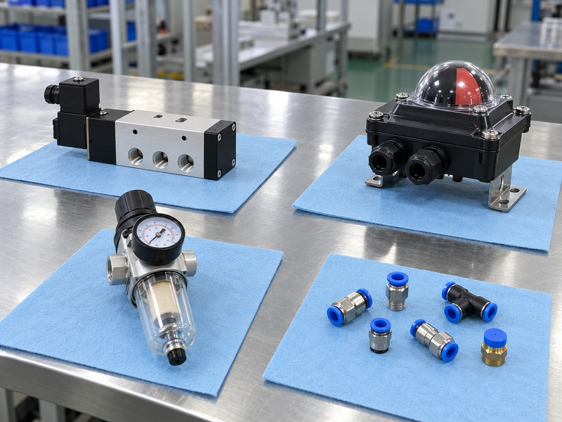
A pneumatic high performance butterfly valve reaches a defined failure position only when the complete pneumatic and electrical circuit supports that action. Double-acting actuation uses air in both directions. Loss of supply can leave the assembly drifting or load-dependent unless a separate engineered holding or stored-energy arrangement exists. A spring-return actuator also needs adequate spring output against the actual process load.
Which failure should your test reproduce?
Specify loss of instrument air, loss of electrical power and loss of control signal separately. Solenoid configuration, positioner response, exhaust restrictions and stored air can change the outcome. A closed indication switch confirms its own setpoint; it doesn’t prove seat tightness. Keep normal stroke time and failure stroke time in the acceptance plan. Fast closing can create a damaging pressure transient, so the process designer must approve the allowed timing rather than selecting the fastest accessory package.
- Define each loss condition separately.
- Confirm spring direction and endpoint output.
- Test feedback independently from shutoff leakage.
| Condition | Verify on the assembled package |
|---|---|
| Air loss | Final position and travel time |
| Power loss | Solenoid and positioner response |
| Signal loss | Configured response and indication |
Use a witnessed functional test to close the failure-action requirement.
7. Will the disc clear your pipework?
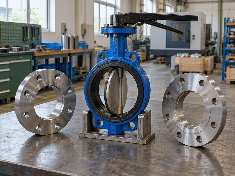
A pneumatic high performance butterfly valve fits a line only when flange dimensions, face-to-face length and disc sweep all match. Nominal diameter doesn’t establish the available internal clearance. Thick-wall pipe, a lining, a nearby reducer or a gasket projecting into the bore can obstruct travel. A valve that turns freely on a bench may bind after installation.
What belongs on the interface drawing?
Show mating flange standard, drilling, bore, gasket arrangement and bolt details. Review the flanged butterfly valve drawing against the actual pipe schedule and adjacent components. Keep wafer, lug and double-flanged arrangements distinct. End-of-line use needs a separately stated rating and installation condition. Also check actuator height, maintenance clearance and the support loads imposed by the assembly. The valve should not pull misaligned pipe ends together during bolting.
- Check the full disc opening envelope.
- Use the approved gasket and bolt arrangement.
- Confirm separate end-of-line conditions where needed.
| Interface check | Common source of mismatch |
|---|---|
| Bore clearance | Pipe wall or internal lining |
| Face-to-face length | Different structural series |
| Access envelope | Actuator, override or adjacent equipment |
Release installation drawings only after the pipe and valve dimensions agree.
8. Which tests demonstrate the ordered duty?
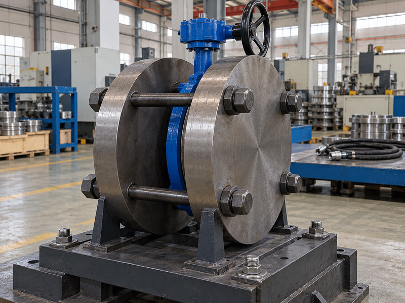
A pneumatic high performance butterfly valve requires separate evidence for pressure integrity, shutoff and operation. A shell test checks the pressure boundary under its stated conditions. It doesn’t establish seat leakage, operating torque, failure action or suitability for a different fluid. Keep test pressure, allowable operating pressure and maximum closing differential pressure in separate fields.
What should the report contain?
Specify the governing test method, medium, temperature, direction, hold time and acceptance criterion. Tie each record to the product identity and approved revision. A metal-seat acceptance limit may differ from a soft-seat limit; don’t convert a general tight-shutoff phrase into an unrestricted zero-leakage promise. Where the service needs gas tightness or hot operation, request the relevant additional evidence. For hazardous fluids, the project must define the qualification scope rather than relying on an ordinary ambient water test.
- Record test direction and pressure.
- Match instruments and calibration records.
- Keep functional and leakage results distinct.
| Test | Main evidence |
|---|---|
| Shell integrity | Pressure-boundary report |
| Closure leakage | Defined direction and acceptance limit |
| Assembled operation | Travel, feedback and failure action |
Reject reports that cannot be matched to the supplied valve.
9. Can this valve regulate your flow range?
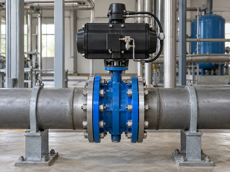
A pneumatic high performance butterfly valve can provide control duty when its flow characteristic and operating limits suit the process. Valve angle is not the same as flow percentage. Available pressure drop, fluid properties and the installed system determine the actual response. A positioner controls shaft position; it cannot correct an unsuitable valve size or eliminate cavitation by itself.
What data should the calculation use?
Request coefficients by opening position, the recommended control range and any relevant noise or cavitation assessment. For an illustrative water calculation, Q = 100 m³/h at a valve pressure drop of 0.2 bar needs Kv of about 223.6 when relative density is 1. That number establishes a calculation point, not a selected valve size. Repeat the assessment at minimum and maximum flow, then examine the usable opening range. Gas and two-phase service require their applicable sizing methods.
- Submit minimum, normal and maximum flows.
- State upstream and downstream pressures.
- Verify the permitted control range.
| Input | Why it changes selection |
|---|---|
| Density and viscosity | Changes liquid sizing |
| Available pressure drop | Changes required coefficient |
| Minimum flow | Reveals poor low-opening operation |
Choose the assembly using the operating range, not the pipe diameter alone.
10. What should you hand over before startup?
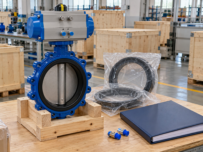
A pneumatic high performance butterfly valve is ready for handover when the approved configuration, inspection results and commissioning instructions match the installed assembly. Keep a record of actuator size, air pressure, failure direction, accessories and travel settings. A replacement solenoid or coupling should go through the same review as another component that affects operation.
What does the maintenance team need?
Provide the installation manual, spare-part identity, test records and settings that operators will check later. Record the as-installed valve orientation and maintenance access with photographs. Use isolation and depressurization procedures before investigating binding, leakage or a damaged seat. For RUITO enquiries, submit the fluid, temperature, working pressure, closing differential, flange details, duty cycle and minimum air supply. The engineering review can then identify a supported configuration and any gaps requiring a different design.
- Hand over the approved drawing and material list.
- Record actual commissioning settings.
- Name the replacement parts and revision.
| Handover item | Owner’s check |
|---|---|
| Configuration file | Matches installed equipment |
| Test package | Traceable product identity |
| Maintenance plan | Correct parts and safe access |
Send your operating data and contact us for a configuration review before releasing the purchase order.
FAQ
Q1: Can I use a water valve for compressed air?
Only if the exact assembly has an approved gas-service specification. Water testing alone doesn’t establish gas leakage performance or suitable shaft retention.
Q2: How do I know whether the actuator is undersized?
Compare its available output at minimum dynamic air pressure with required torque throughout both strokes. Check mechanical binding before changing actuator size.
Q3: Can I use a double-acting actuator for fail-close duty?
Only with a separately engineered failure-action arrangement. Ordinary double-acting actuation doesn’t guarantee closure after air loss.
Q4: Does a Class flange establish the valve rating?
No. Confirm the complete valve’s pressure–temperature rating, seat differential limit and connection requirements independently.
Q5: What’s the best information to send with an enquiry?
Send the full operating envelope, fluid composition, pipe interface, function, failure action and minimum dynamic air pressure. Include the project acceptance criteria.