
Fit a double eccentric butterfly valve lug type by verifying the complete flange, bore, bolt and operator interfaces before installation. A compact replacement can still need different fasteners or interfere with an adjacent liner. Build a dimensional acceptance sheet from the actual pipework, then use the approved drawing and installation manual to close each mismatch before the shutdown.
1. What does double eccentric butterfly valve lug type specify?
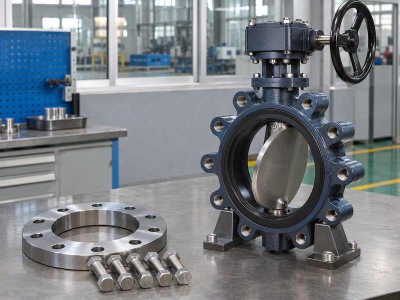
The schedule entry double eccentric butterfly valve lug type specifies operating geometry and body connection, but leaves several installation dimensions unresolved. It does not identify face-to-face length, flange drilling, facing, thread depth or operator envelope.
Turn the description into a measured interface
Start with a site survey and a controlled general arrangement drawing. Record the gap between mating faces, pipe bore, flange outside diameter, hole pattern and nearby obstructions. Include insulation and access platforms where they affect the operator. Mark any measurement that remains provisional so it cannot silently become a manufacturing dimension.
- Photograph the existing tag and flange faces.
- Record the drawing revision used for comparison.
Resolve the offered construction
Check the section drawing separately from the outside dimensions. RUITO's documented concentric lug and double eccentric double flanged ranges are distinct configurations. A request combining double eccentric geometry with a lug body needs written confirmation, its own dimensional basis and an approved material list.
| Schedule field | Installation document |
|---|---|
| Body connection | Flange and fastening detail |
| Offset geometry | Controlled section view |
| Operator | Overall envelope and mounting drawing |
Key takeaway: Release installation planning only against a complete, identified configuration.
2. Can double eccentric butterfly valve lug type replace wafer?
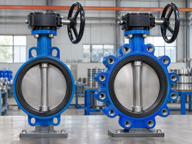
A double eccentric butterfly valve lug type can replace a wafer valve only after the interfaces and service ratings have been checked. Both may fit between pipe flanges, but the way their bolts restrain the body can differ. You cannot approve the change from nominal diameter or face-to-face length alone.
Compare the actual fastening paths
A typical wafer butterfly valve uses through bolts between the pipe flanges. A threaded lug construction normally uses separate fasteners from each side. Check whether the proposed body instead has through-hole lugs or a special arrangement.
- Confirm fastener diameter and thread form.
- Check required engagement on both sides.
Reassess the maintenance arrangement
A lug connection can change how a spool is removed, but maintenance convenience does not establish end-of-line suitability. Obtain a separate statement for any condition with a mating flange absent. Pipe support, seat retention and pressure direction remain part of the assessment. The comparison image illustrates body connections; it does not prove either valve's offset geometry.
| Feature | Replacement check |
|---|---|
| Face-to-face | Compare actual drawing dimensions |
| Fasteners | Approve length and engagement |
| Spool removal | Confirm permitted restraint arrangement |
Key takeaway: Treat a wafer-to-lug replacement as an engineering change.
3. How does double eccentric butterfly valve lug type differ?
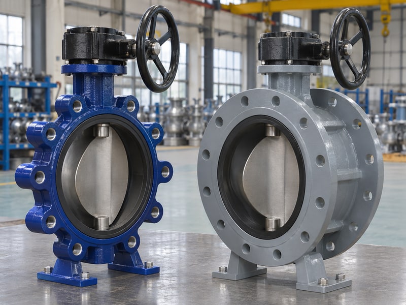
A double eccentric butterfly valve lug type differs from a double flanged valve mainly in the pipe connection when comparing otherwise specified designs. Double eccentric describes the disc and shaft geometry. Double flanged describes two integral body flanges. Neither expression determines all the materials, ratings or maintenance characteristics.
Compare connection and geometry on separate lines
A flanged butterfly valve can have concentric or eccentric internals depending on its series. A lug body can also house different operating geometries. A flange-style preference does not establish lower torque or better seat tightness.
- Record body style without inferring pressure class.
- Record geometry without inferring seat material.
Check structural and handling implications
Compare installed length, mass, lifting points, support needs and tool access for the offered sizes. Do not assume one connection always handles more pipe load or vibration. Installation loads must stay within the supplier's limits. A heavier body also needs a lifting and support plan that avoids applying force through the handwheel, shaft or actuator.
| Design term | What still needs confirmation |
|---|---|
| Double eccentric | Offset dimensions and seat design |
| Lug body | Fastening and permitted external loads |
| Double flanged body | Flange details and installed envelope |
Key takeaway: Use like-for-like drawings when comparing body styles.
4. Which seats fit double eccentric butterfly valve lug type?
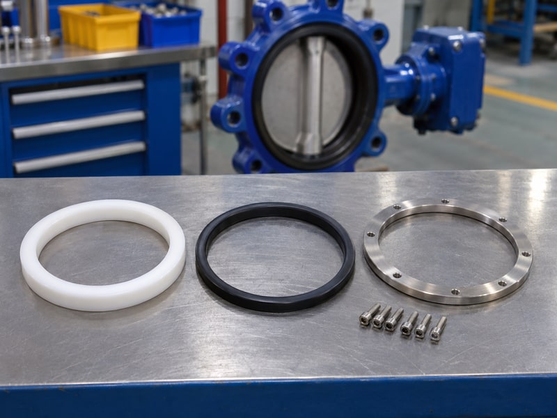
Seat selection for a double eccentric butterfly valve lug type depends on the fluid and complete operating cycle. A material that suits normal water temperature may not suit cleaning chemicals, hot standby or oil contamination. Review the seat, packing and auxiliary seals against the same duty sheet rather than approving each from a different brochure.
Match the seal assembly to the service
Ask for an identified seat compound or material grade, its support arrangement and the associated pressure-temperature curve. Include fluid concentration and expected deposits. A PTFE seat ring does not mean the body and shaft are continuously lined. If corrosion isolation is required, review every exposed wetted surface and the actual lining construction.
- Include flushing and cleaning fluids.
- Record any vacuum or low-pressure condition.
Plan access for replacement
Find out which side releases the seat retainer and what must be removed. Check whether the work requires complete valve removal or a controlled workshop procedure. Keep replacement parts tied to the approved bill of materials and revision. A ring with the same nominal diameter can still have a different profile, stiffness or retention detail.
| Maintenance question | Required answer |
|---|---|
| What is replaced? | Identified seal kit and revision |
| Which access is needed? | Approved dismantling procedure |
| What follows repair? | Specified adjustment and retest |
Key takeaway: Buy the maintenance procedure with the seal configuration.
5. What flow suits double eccentric butterfly valve lug type?
A double eccentric butterfly valve lug type suits a proposed flow only after hydraulic and dynamic conditions have been checked. Maximum flow is one case. Minimum controllable flow, partly open operation, downstream pressure and pump transients can create different limits. The valve's connection style cannot supply those answers.
Request the relevant flow curve
Use Kv or Cv values tied to the actual size and opening angle. Supply fluid density, viscosity, inlet and outlet conditions, and allowable loss. For liquid throttling, review cavitation and flashing where relevant. Compressible service needs its own calculation method and operating limits, rather than a direct substitution into a water calculation.
- Identify isolation and throttling periods separately.
- Ask for the allowed operating-angle range.
Check the surrounding pipework
Reducers, elbows, pumps and nearby equipment can affect flow distribution and loads. Confirm any installation-distance requirement in the supplied manual or project calculation. Avoid universal spacing rules copied from a different valve type.
| Operating case | Data for review |
|---|---|
| Maximum flow | Pressure loss and dynamic load |
| Minimum flow | Stable operating position |
| Closure | Differential pressure and system transient |
Key takeaway: Evaluate the flow range and the piping layout together.
6. What drives double eccentric butterfly valve lug type?
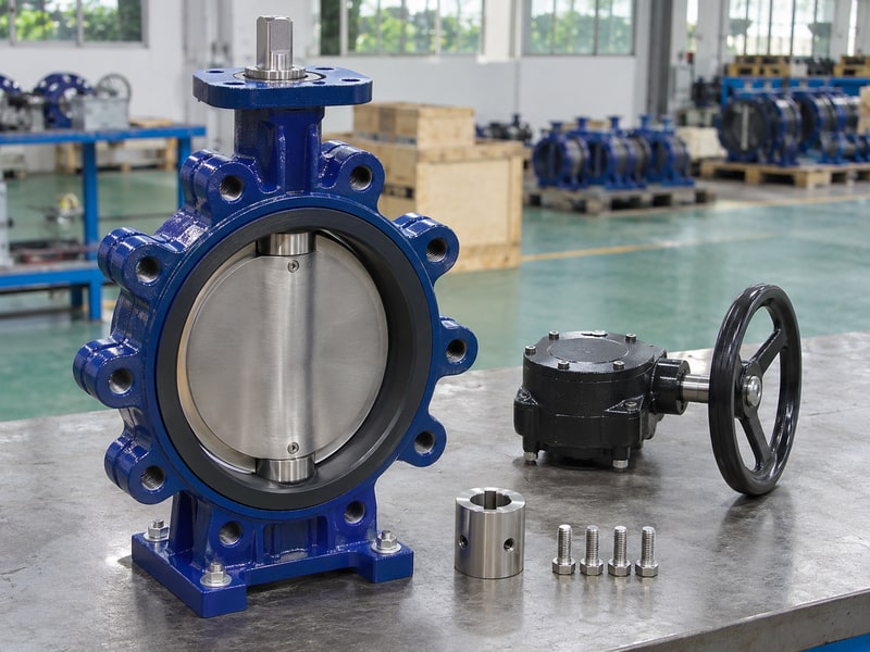
A double eccentric butterfly valve lug type needs an operator that covers the complete required torque envelope without exceeding shaft or stop limits. A matching mounting pad confirms an interface. It does not establish adequate actuator output, correct coupling engagement or acceptable closing force under the maximum differential pressure.
Verify the mechanical drive stack
Check the mounting pattern, shaft dimensions, coupling fit, bracket stiffness and fastener access. For an ISO 5211 part-turn actuator attachment, confirm the contracted edition and dimensions against the approved drawing. Keep the coupling engaged through the approved length without bottoming or forcing misalignment. A gearbox position mark should agree with verified disc travel.
- Check handwheel sweep and maintenance clearance.
- Identify approved lifting points separately.
Check output at the available supply
For pneumatic equipment, compare output through the stroke at minimum available air pressure. For electric equipment, confirm supply, duty, limits and feedback. Set travel stops using the valve and actuator instructions. Increasing a stop setting or torque limit to overcome binding can damage components and conceal an installation fault.
| Drive check | Evidence |
|---|---|
| Mounting interface | Matched pad, bracket and coupling drawing |
| Available output | Calculation at minimum supply |
| Closure setting | Approved stop and limit procedure |
Key takeaway: Approve the whole drive assembly, including its field settings.
7. How is double eccentric butterfly valve lug type installed?
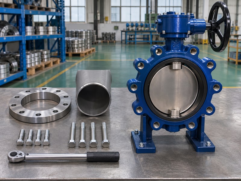
A double eccentric butterfly valve lug type is installed using its approved IOM, with supported pipework and a verified disc-clearance envelope. Isolate, drain and establish a safe work condition before opening the line. Remove transport protection only when the assembly is ready and protect sealing faces from grit or mechanical damage.
Prepare the faces and fasteners
Check flange condition, alignment and the specified gasket arrangement. Some seat constructions form part of the flange seal; others require a separate gasket. Follow the actual manual. Calculate bolt length from the complete assembly stack and approved engagement, while leaving the required bottoming clearance in blind holes.
- Confirm no bolt reaches an internal moving part.
- Keep welding heat and debris away from the valve.
Check movement at the specified stage
The disc position during insertion, tightening and function checks is design-specific. Use the sequence in the supplied instructions instead of applying a generic open-or-closed rule. Confirm movement without forcing contact against a pipe bore, liner or adjacent component. Tighten in the specified pattern with the prescribed torque and record any dimensional exception.
| Assembly stage | Check before proceeding |
|---|---|
| Insertion | Required disc position and clear bore |
| Tightening | Correct gasket, bolts and sequence |
| Function check | Free travel without interference |
Key takeaway: Stop at an unexplained interference instead of applying more force.
8. How do you test double eccentric butterfly valve lug type?
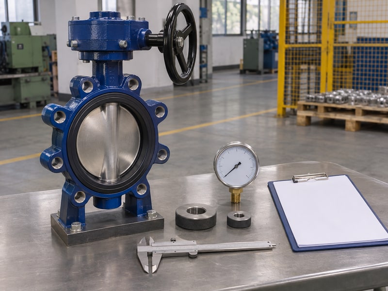
Testing a double eccentric butterfly valve lug type requires separate factory acceptance and site commissioning plans. Factory shell and seat results address defined inspection conditions. Site checks address the installed interfaces, operator and system. Neither stage should quietly substitute a different fluid, pressure direction or leakage criterion for the agreed requirement.
Establish the acceptance record
State the governing test procedure, medium, temperature, pressure, hold time and acceptance limit. Identify the unit and its material and assembly records. If reverse closure, gas leakage or end-of-line performance is required, put it into the inspection plan. A report for another size or seat assembly needs an explicit technical justification before use.
- Check instrument calibration validity.
- Record required witness and hold points.
Commission without exceeding the rating
Use the approved site procedure and safe isolation boundaries. Check flange leakage, indication, control signals and the agreed operating sequence. Do not treat the factory shell-test pressure as a permitted site operating pressure. Where system testing exceeds a component's limit, the responsible project engineer must define how that component is protected or isolated.
| Record | What it establishes |
|---|---|
| Factory pressure report | Stated inspection result |
| Operator function record | Travel and signal verification |
| Site commissioning sheet | Installed-system acceptance checks |
Key takeaway: Preserve both the factory record and the installed commissioning record.
9. How is double eccentric butterfly valve lug type maintained?
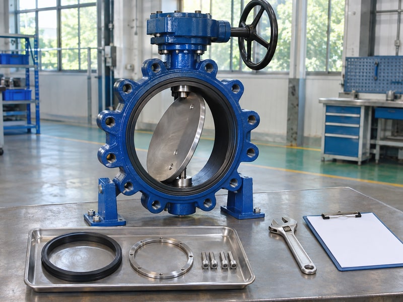
Maintenance of a double eccentric butterfly valve lug type follows the identified configuration, operating history and supplier procedure. Leakage can come from a flange interface, shaft packing or seat assembly. Locate the leak and establish safe isolation before adjusting or removing components. External appearance alone cannot identify the failed pressure boundary.
Diagnose before dismantling
Record fluid, temperature, pressure direction, operating position and symptoms. Compare current movement or torque with the commissioning baseline. Look for pipe strain, contamination and changes to stop settings. Do not retighten packing or remove an operator under pressure unless an approved procedure explicitly permits that task and defines the controls.
- Separate flange, packing and seat leakage reports.
- Retain the original settings and component identification.
Control replacement and return to service
Use approved spares with traceable material and revision details. Inspect the disc edge, seat support, shaft connection and bearing condition as directed by the manual. After reassembly, complete the specified functional and leakage tests. Changing a seal material can affect compatibility, torque and the approved pressure-temperature limit, so handle it through technical change control.
| Symptom | Investigation starting point |
|---|---|
| Rising operating effort | Interference, deposits and drive settings |
| External leak | Flange or shaft-packing boundary |
| Passing closed valve | Seat condition and closure setup |
Key takeaway: Keep the repair record connected to the unit's original configuration.
10. How is double eccentric butterfly valve lug type ordered?
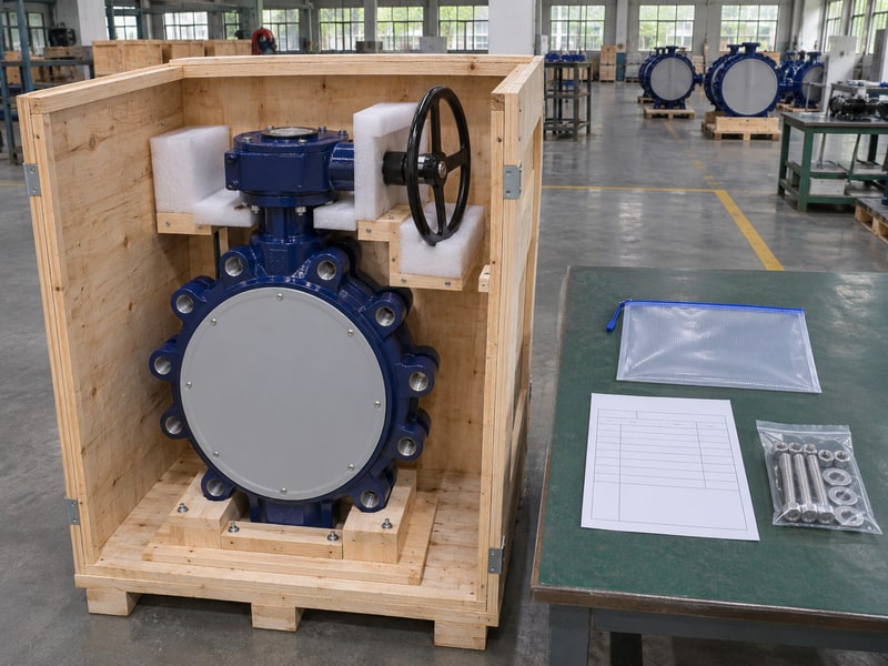
A double eccentric butterfly valve lug type should be ordered with an interface schedule and an agreed documentation package. Include the fluid, operating cases, flange standard, facing, bore, installed length, operator envelope and fastening requirements. Resolve departures from the existing installation before approving manufacture or booking the shutdown.
Build a useful replacement package
Send the measured site dimensions alongside the equipment tag and photographs. Ask for the supplier's drawing, wetted materials list, performance limits, torque calculation and IOM. The lug butterfly valve page can help identify the connection family, but the final offer must confirm double eccentric geometry and the required duty separately.
- Agree the spare-parts list and maintenance access.
- Freeze drawing and material revisions in the order.
Tie delivery to installation readiness
Define factory release, shipping protection, document submission and site acceptance as separate milestones. Check that caps protect the sealing faces and that packing carries the valve's weight without loading the shaft or handwheel. Confirm who supplies bolts and gaskets.
| Handover item | Site benefit |
|---|---|
| Approved interface drawing | Fit checked before shutdown |
| Identified bolts and seals | Assembly materials ready |
| IOM and test package | Commissioning criteria available |
Key takeaway: Prepare the complete installation package before dispatch. Send your site measurements when you contact us for a configuration and interface review.
Frequently asked questions
Q1. Can I keep the old face-to-face dimension?
Only if the new approved drawing matches it. Body style and nominal size do not guarantee the same installed length. Measure the pipe gap and compare the specified dimensional series.
Q2. How do I know whether I need flange gaskets?
Use the supplied installation manual. The requirement depends on the seat and flange-sealing design. Adding a gasket without approval can alter clamping, alignment and disc clearance.
Q3. Can I turn the actuator around to gain clearance?
Only through the approved reorientation procedure. Check coupling engagement, mounting loads, stops, indication and cable or air connections before commissioning the changed position.
Q4. What's the best way to avoid a wrong bolt length?
Calculate the complete assembly stack against the fastening drawing. Verify thread engagement and blind-hole bottoming clearance on each side. Do not choose length from nominal valve diameter.
Q5. Can I remove the downstream pipe with this valve closed?
Obtain a separate end-of-line approval and follow the site's isolation procedure. A threaded lug body alone does not prove a suitable retained pressure boundary or personnel isolation arrangement.