
Choose a double flanged triple offset butterfly valve by matching its approved dimensions, flange interfaces, moving-disc clearance, and operating envelope with your pipework. Nominal size can look correct while the valve is too long, the bolt access is blocked, or the open disc meets an adjacent fitting. Check the installed arrangement before releasing a replacement order.
1. What is a double flanged triple offset butterfly valve?
It is a triple-offset butterfly valve with a flange at each pipe connection. A double flanged triple offset butterfly valve combines an external connection arrangement with an internal sealing design. Review those two descriptions separately. The presence of two flanges does not establish the actual offset geometry, seal construction, or operating limits.
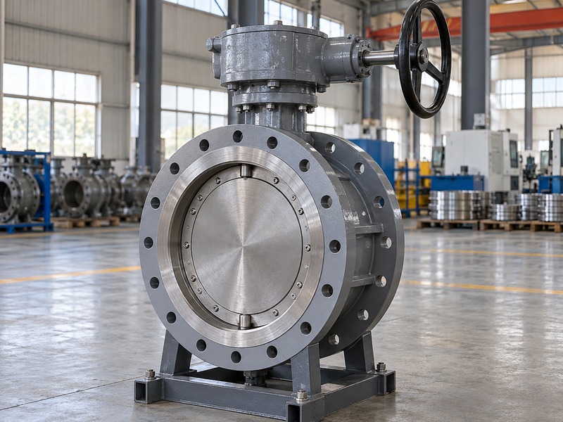
Start with the installed duty
Identify the required isolation performance, fluid, temperature, line pressure, and closing differential. Then confirm why a double-flanged connection suits the layout. The review may involve existing companion flanges, an agreed face-to-face pattern, handling arrangements, or maintenance access.
Ask the supplier to identify the exact assembly and connection drawing. A catalogue family photograph cannot settle dimensions for every size or operator configuration. Keep any proposed alternative construction visible in the technical comparison.
- Define the actual service and isolation duty.
- Identify the required body and sealing construction.
- Request the controlling installation drawing.
| Description | What it identifies |
|---|---|
| Double flanged | Two flanged pipe connections |
| Triple offset | Specified internal geometry |
| Approved configuration | Actual materials, interfaces, and limits |
2. How do you choose the face-to-face pattern?
Choose the specified pattern that fits the approved piping arrangement and project requirements. A double flanged triple offset butterfly valve needs a confirmed face-to-face dimension for its selected size and construction. A different pattern can change the installation gap even when nominal size and flange drilling match. Record the controlling dimension and drawing revision.
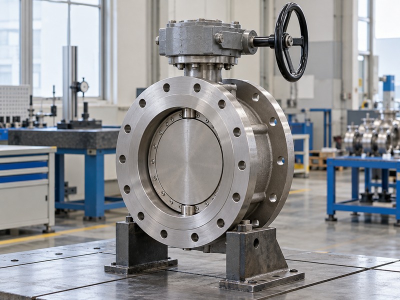
Measure the available installation gap
For replacement work, collect the existing valve drawing and verify the site arrangement. Identify the flange faces used as measurement datums and whether the recorded gap includes gaskets. Pipeline movement, dismantling arrangements, and tolerances can affect the usable space. Close a length discrepancy before manufacture or dispatch.
Ask the supplier to identify any applicable short or long pattern explicitly. For an API 609 order, check the required edition against the official publication notice and project specification. Do not select a length from an unrelated table merely because the product description sounds similar. Where a standard permits an agreed dimension, record that agreement in the order.
- Confirm the required face-to-face basis.
- Record the site measurement datums.
- Include the installation tolerance and gasket arrangement.
| Length input | Check to perform |
|---|---|
| Valve drawing | Selected size and pattern |
| Site gap | Actual flange-face datums |
| Assembly allowance | Gaskets and permitted installation movement |
3. Which flange details must match the pipework?
The flange standard, facing, drilling, dimensions, and fastener arrangement must match the approved joint. For a double flanged triple offset butterfly valve, a pressure-class or PN label alone does not establish interchangeability. Compare the actual valve and companion-flange details. Include the selected gasket and available bolt access in that comparison.
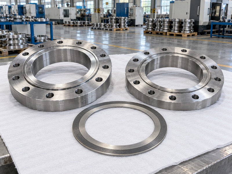
Compare actual mating drawings
Record the required standard and relevant size range. Check facing type, bolt-circle dimensions, hole size, and the specified fasteners through the approved drawings. A near match can still create an unsuitable joint. Keep any proposed adapters, flange substitutions, or other interface changes within the piping design review.
RUITO's documented wafer butterfly valve connection details illustrate another body arrangement. Their bolting or installation dimensions should not be transferred to a double-flanged assembly without confirming the selected design.
- Identify both mating flange specifications.
- Compare drilling and facing details.
- Confirm the complete joint arrangement.
| Flange item | Required match |
|---|---|
| Standard and size | Approved pipe and valve interface |
| Facing | Compatible gasket and sealing surfaces |
| Bolting | Correct geometry, engagement, and access |
4. How do you verify the open-disc clearance?
Compare the valve's moving-disc envelope with the actual adjacent pipe and fitting bore. A double flanged triple offset butterfly valve can have a disc that extends beyond the valve body during movement. The required clearance depends on the selected design. Check the supplier's minimum bore or envelope information rather than using nominal pipe size as the answer.
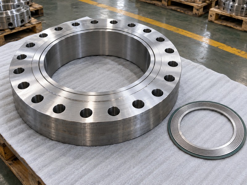
Include the nearest restrictions
Look at pipe wall thickness, internal lining, weld profiles, reducers, and nearby fittings where they can enter the moving envelope. Gaskets also need the correct internal opening. An apparently generous bore can contain a local restriction that is absent from a simple nominal-size comparison.
Review clearance through the required movement, not just at one photographed position. For replacement work, record the actual adjacent arrangement and any uncertainty that requires measurement or supplier confirmation. Keep the permitted movement check within the approved installation procedure. Resolve interference before final assembly.
- Obtain the selected disc-envelope requirement.
- Identify nearby internal restrictions.
- Confirm the actual adjacent bore and gasket opening.
| Possible restriction | Evidence to check |
|---|---|
| Pipe bore or lining | Actual internal dimensions |
| Fitting or reducer | Local geometry near the disc |
| Gasket opening | Specified internal diameter and position |
5. How should the flange gaskets be selected?
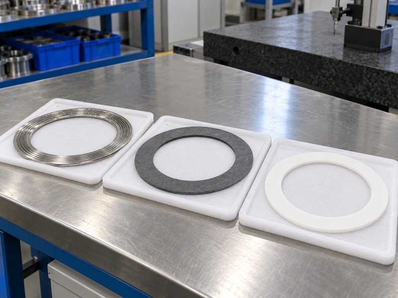
Select gaskets that suit the specified flange faces, fluid, temperature, pressure, and installation requirements. A double flanged triple offset butterfly valve needs a defined joint-sealing arrangement at each end. Its internal metal seat does not select the flange gasket for you. Use the valve, piping, and gasket suppliers' applicable instructions to establish the approved joint.
Check dimensions and assembly conditions
Confirm gasket outside and inside dimensions, thickness, construction, and compatibility with the flange facing. Review storage and surface condition before installation. A damaged or incorrectly positioned gasket can create an external leak even when the valve's internal closure meets its criterion.
Keep joint tightening separate from valve seating adjustment. Flange-bolt force should follow the approved joint procedure. If the assembled valve has a shutoff problem, investigate its cause through the manufacturer's procedure rather than treating extra flange-bolt load as a correction.
- Confirm the specified gasket at each connection.
- Check condition and internal opening.
- Follow the approved tightening procedure.
| Gasket detail | Review question |
|---|---|
| Construction | Does it suit the fluid and conditions? |
| Dimensions | Does it fit the facing and preserve clearance? |
| Installation | Is the approved procedure available? |
6. How do you check bolt length and access?
Check the fastener arrangement against the assembled joint and the valve drawing. A double flanged triple offset butterfly valve needs suitable bolt or stud length, engagement, clearance, and tool access. The body, flange thickness, gasket, washers where specified, and nut arrangement all affect the result. Confirm these details before ordering installation hardware.

Review the difficult positions
Inspect the bolt positions nearest the valve neck, gearbox bracket, support feet, or adjacent equipment. A fastener can fit the hole yet remain impossible to insert or tighten after the operator is mounted. Agree on the installation sequence where access is restricted.
Use the specified fastener materials and joint procedure. Avoid choosing a tightening value from an unrelated valve because the nominal size matches. Any change to the joint arrangement should be checked for its effect on hardware length, access, and the required assembly conditions.
- Verify the complete joint thickness.
- Check insertion and tool clearance.
- Confirm hardware and assembly requirements.
| Fastener check | Detail to review |
|---|---|
| Length and engagement | Complete approved joint stack |
| Access | Neck, bracket, and nearby equipment |
| Assembly | Materials and tightening procedure |
7. How do pressure direction and orientation affect layout?
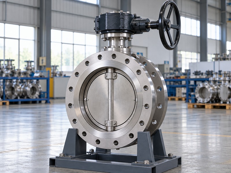
They affect the required valve arrangement, operator assessment, and installation checks. For a double flanged triple offset butterfly valve, confirm the meaning of the manufacturer's direction marking and any preferred pressure direction. Normal flow alone may not identify the highest differential during every operating case. State any required reverse shutoff duty explicitly.
Check the selected installation instructions
The permitted shaft position and operator orientation can depend on the model, service, and maintenance requirements. Use the selected instructions and approved layout. Do not rotate an operator to clear an obstruction without reviewing the coupling, bracket, enclosure, and access implications.
Double-flanged construction also does not automatically establish end-of-line duty. If one side may be disconnected while the other is pressurized, request the specific approval and operating restrictions for that condition. The site's isolation procedure remains a separate requirement. Record the accepted orientation on the installation drawing.
- Identify normal and reverse differential cases.
- Confirm installation markings and shaft position.
- Define any special end-of-line requirement.
| Layout question | Confirmation needed |
|---|---|
| Pressure direction | Applicable model instructions and duty |
| Shaft and operator position | Permitted arrangement and access |
| End-of-line condition | Explicit configuration-specific approval |
8. How do alignment and supports affect the joint?
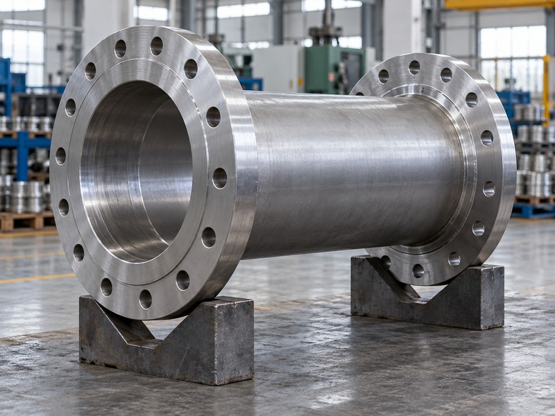
Correct alignment and support help the installed assembly meet its intended mechanical conditions. A double flanged triple offset butterfly valve should fit the approved pipe arrangement without being used to correct misaligned pipework. Review pipe supports, valve weight, operator weight, and any specified external-load limits. Keep these requirements with the piping design and installation team.
Review loads through installation and service
Check the support arrangement before final joint tightening. Thermal movement, nearby equipment, and maintenance removal can change the loads carried by the assembly. Where external-load information is required, obtain it for the selected valve and arrangement rather than assuming the flange rating covers every imposed load.
Plan how the valve and operator are supported during installation and removal. Temporary handling arrangements should follow the approved method and identified lifting points. Protect the sealing faces and moving parts while the assembly is positioned. Correct the installation arrangement before loading the joint.
- Confirm pipe alignment and support readiness.
- Review relevant operating and maintenance load cases.
- Agree on the handling and temporary-support method.
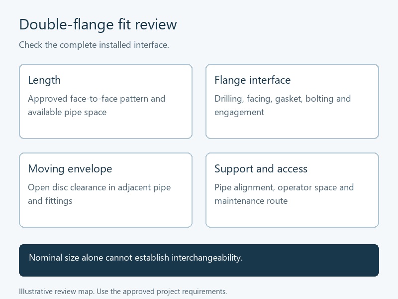
| Mechanical item | Review basis |
|---|---|
| Pipe alignment | Approved joint geometry |
| Supports | Weight, movement, and maintenance cases |
| Handling | Approved points and positioning method |
9. What operator and maintenance space should you reserve?
Reserve space for operation, connections, inspection, and planned component removal. A double flanged triple offset butterfly valve needs more room than its body dimensions alone suggest. Include the gearbox or actuator, handwheel travel where relevant, cable or air access, and maintenance clearances. Check the full envelope against nearby structures and equipment.
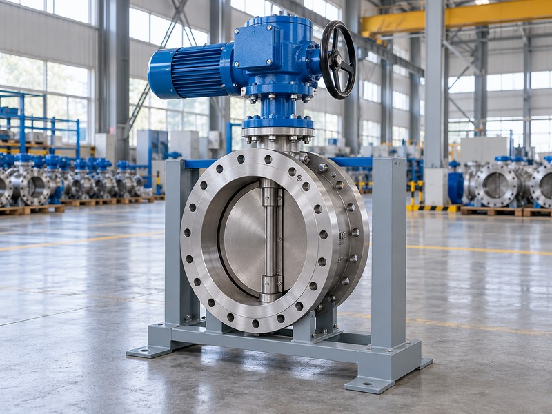
Check the removal route
Ask which components can be serviced and what must be removed first. Seal or shaft-related work may require access through a pipe connection or removal of the valve, depending on the selected construction. Include lifting and support space in the maintenance plan.
If an operator orientation changes after approval, revisit these clearances. A small rotation can move a terminal box, handwheel, or maintenance cover into an obstruction. Keep the final arrangement tied to the actual operator and valve drawings.
- Check local operation and connection access.
- Review service-cover and component-removal space.
- Confirm the handling route for planned maintenance.
| Space allowance | What it supports |
|---|---|
| Operator envelope | Normal operation and connections |
| Maintenance access | Inspection and permitted service work |
| Removal route | Supported handling of planned components |
10. What should you approve before a replacement order?
Approve the matched duty, dimensions, interfaces, and verification scope before releasing the order. For a double flanged triple offset butterfly valve, keep the original site information and proposed replacement drawing in the same review. Record differences explicitly. A matching nominal size is only one part of the comparison.
Send a complete interface enquiry
Provide the fluid and operating conditions, existing drawings, measured installation gap, companion-flange details, adjacent bore, operator requirements, and access constraints. RUITO's manufacturing and inspection information can support the discussion. Its documented flanged range includes concentric and double-offset configurations; confirm the availability and evidence for a proposed triple-offset construction separately.
- Close dimensional and technical deviations.
- Confirm the required inspection records.
- Freeze the final installation arrangement.
| Release item | Accepted information |
|---|---|
| Service | Configuration-specific operating duty |
| Fit | Length, connection, clearance, and access |
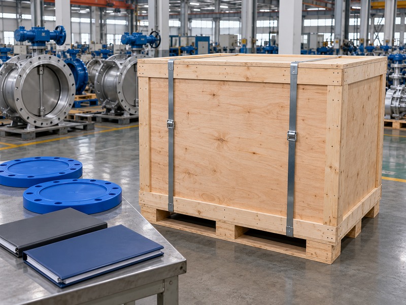
| Delivery | Verified documents and protective packing |
To review your double flanged triple offset butterfly valve interface, contact us with the site dimensions and proposed data sheet.
Questions buyers ask about double-flanged replacements
Q1. Can I replace a gate valve with the same nominal size?
Only after checking the full interface and duty. Face-to-face length, moving clearance, operator space, and supports can differ.
Q2. Does a matching flange pattern prove equal pressure ratings?
No. Confirm the selected valve's pressure-temperature and closing-differential limits separately from its drilling pattern.
Q3. How do I know whether the open disc will fit?
Compare the supplier's moving envelope with the actual adjacent bore, fittings, lining, and gasket opening.
Q4. Can I remove one pipe side while the valve is pressurized?
Only where the selected configuration and site procedure explicitly permit that duty. Double-flanged construction alone is insufficient.
Q5. What's the best information to send for a replacement quote?
Send the existing drawing, measured interfaces, actual duty, operator requirements, and maintenance constraints. Identify uncertain measurements clearly.