
Use the accepted project legend for a symbol for butterfly valve with tamper switch, then trace its valve tag through the electrical schematic and system point list. Confirm which marks describe the valve, its operator and position contacts. A recognizable shape alone cannot define the supplied assembly or required system response.
A piping drawing can mark a supervised valve while its tag leads to no matching input in the point list. The symbol looks complete, yet purchasing cannot identify the switch variant and the system reviewer cannot trace its report. Review the legend and cross-references before accepting the mark as a finished description of the valve’s supervisory function.
1. What defines a symbol for butterfly valve with tamper switch?
The project legend defines a symbol for butterfly valve with tamper switch within the drawing set where it appears. Read the mark beside its legend entry, notes and drawing discipline. Similar shapes in another library may describe different functions, so a copied symbol needs review before it can carry the same meaning on your project.
What should the legend entry explain?
Read the stated meaning. Identify the valve type, operator notation and supervisory function assigned to the mark. Record any drafting standard and edition specified by the project without assuming a mandatory universal glyph. Refer unclear meaning back to the drawing owner with the affected tag and document reference.
- Locate the legend that governs the actual drawing.
- Read valve, operator and supervisory marks separately.
- Record unresolved meaning against the affected valve tag.
Key takeaway: Use the accepted legend as the starting point for interpreting the symbol.
| Check | What you should confirm |
|---|---|
| Legend | Accepted entry defines the mark on this project |
| Scope | Drawing discipline and applicable notes are identified |
| Question | Ambiguity has a tag and document reference |

2. Which legend fits a symbol for butterfly valve with tamper switch?
The applicable piping or electrical legend governs a symbol for butterfly valve with tamper switch on that sheet. A piping and instrumentation diagram may summarize valve duty and monitoring, while an electrical schematic defines actual contacts and circuit references. Review their cross-references to connect those definitions.
How should piping and electrical legends stay coordinated?
Keep both drawing contexts. Compare the piping legend’s functional description with the electrical legend and equipment schedule. A monitoring annotation should lead to the selected supervisory arrangement without implying a particular contact pair, cable or module terminal. If the project uses a combined legend, identify which notes define function and which documents provide the detailed electrical and mechanical interfaces.
- Identify the drawing discipline behind each legend entry.
- Link the piping function with the electrical detail.
- Leave terminal and cable definitions in their controlled documents.
Key takeaway: A coordinated drawing set can use different representations of the same identified assembly.
| Check | What you should confirm |
|---|---|
| Piping | Mark describes the intended valve function |
| Electrical | Schematic defines selected contacts and circuit references |
| Coordination | Cross-references connect both document contexts |

3. What tags link a symbol for butterfly valve with tamper switch?
The valve tag links a symbol for butterfly valve with tamper switch to a physical asset and its accepted equipment record. Where the project assigns a separate switch tag, preserve its relationship with that valve. A device label, cable number and input address describe different references and should not silently replace the valve identity.
Which identifiers should the reviewer trace?
Follow the valve tag. Trace the valve record through its supplied operator, switch variant and circuit reference toward the system input. Keep document revisions with that chain to distinguish missing connections from obsolete sheets. Correct repeated tags or unmatched switch references before using the schedule for procurement or handover.
- Connect the valve tag with its physical assembly record.
- Retain separate switch and circuit identifiers where assigned.
- Check tag uniqueness and matching document revisions.
Key takeaway: Preserve the valve identity while tracing the separate monitoring and system references.
| Check | What you should confirm |
|---|---|
| Valve | Tag identifies the intended physical asset |
| Switch | Assigned monitoring reference points back to that valve |
| Circuit | Cable and input records retain their own identities |

4. Can a symbol for butterfly valve with tamper switch show actuation?
A symbol for butterfly valve with tamper switch can show actuation when its accepted legend defines the operator notation. Keep manual operation, powered actuation and position contacts as separate functions. A supervisory contact reports a monitored position relationship; its presence does not establish that the valve has an electric actuator or can move on a panel command.
What could an operator mark leave unresolved?
Separate movement from monitoring. Selected operator documents define valve movement, while switch documents define permitted position-contact functions. The Victaulic installation and wiring instructions distinguish those requirements for their identified assemblies. Request the actual configuration when combined annotations leave the component responsible for each function unclear.
- Read the operator notation through the accepted legend.
- Identify the component that physically moves the valve.
- Identify position contacts through the selected assembly documents.
Key takeaway: A monitoring mark cannot establish powered operation without the selected operator definition.
| Check | What you should confirm |
|---|---|
| Valve | Flow-control function is identified |
| Operator | Actual means of valve movement is defined |
| Monitoring | Selected contacts have their own documented function |

5. Can a symbol for butterfly valve with tamper switch show state?
A symbol for butterfly valve with tamper switch can describe the intended supervised position through its legend or linked notes. That position reference remains separate from NO and NC contact labels. A supervised-open supply valve normally remains fully open, while its selected diagram defines the actual contact continuity in that condition.
How should normal position appear in the records?
Name the position reference. Keep the accepted service position beside the identified model and contact-state description. The TYCO BFV-300/BFV-300C technical sheet identifies distinct open-supervised and closed-supervised models. Specify whether normal open describes a physical valve position or an electrical contact when that phrase appears in project notes.
- State the required physical position without ambiguous abbreviations.
- Match the supervised position with the supplied model.
- Keep contact-state descriptions in the selected electrical reference.
Key takeaway: Write valve-position and contact-state notes so they cannot be mistaken for each other.
| Check | What you should confirm |
|---|---|
| Service | Intended physical position has a clear definition |
| Product | Selected model supports the specified monitored position |
| Contacts | Continuity follows the actual switch reference |

6. Where does a symbol for butterfly valve with tamper switch lead?
A symbol for butterfly valve with tamper switch should lead through cross-references to the selected switch schematic and designated supervisory circuit. That schematic identifies the actual contact functions and lead arrangement. The piping symbol cannot define universal wire colors, terminal assignments or permitted use of an auxiliary contact.
What belongs at the schematic cross-reference?
Locate the selected contact detail. Record the manufacturer document, assembly variant and schematic revision that define the supplied switch arrangement. Preserve supervisory and auxiliary assignments, since their lead provisions and permitted duties can differ. A schematic link must resolve those functions for the identified assembly; a generic SPDT sketch cannot establish that either available contact set may serve the fire-alarm input.
- Link the symbol with the supplied switch schematic.
- Identify the designated supervisory contact function.
- Keep auxiliary use within the selected manufacturer’s restrictions.
Key takeaway: Trace the symbol into a defined contact arrangement before reviewing circuit compatibility.
| Check | What you should confirm |
|---|---|
| Reference | Cross-reference resolves to an identified schematic revision |
| Supervision | Designated contact serves its permitted monitored function |
| Auxiliary | Separate contact duty remains explicitly assigned |

7. What point fits a symbol for butterfly valve with tamper switch?
The point associated with a symbol for butterfly valve with tamper switch must match the valve’s accepted supervisory function and actual system input. Trace the tag into the point list and cause-and-effect record. Point text should identify the intended asset and event without implying waterflow detection or hydraulic availability from a position contact.
What should the point and cause-and-effect records agree on?
Follow the reporting reference. Match the physical valve, designated contact function, monitored input and intended system event. For an addressable module, ordinary valve contacts use its specified monitored input or IDC; the module’s separate SLC interface joins a compatible panel bus. The cause-and-effect record defines approved system responses, while the actual module and panel documents define electrical compatibility and configuration.
- Match the valve tag with the correct input point.
- Use event wording that describes the intended supervised condition.
- Keep cause-and-effect decisions linked to accepted system documents.
Key takeaway: Carry the same asset and functional meaning from the symbol through the system point records.
| Check | What you should confirm |
|---|---|
| Identity | Point description traces back to the physical valve |
| Interface | Monitored input and panel bus remain separately defined |
| Response | Accepted cause-and-effect record states the required system action |

8. Can a symbol for butterfly valve with tamper switch prove layout?
A symbol for butterfly valve with tamper switch cannot establish physical layout without the selected assembly and installation drawings. Schematic placement need not represent real orientation, pipe spacing or access. Review operator clearance, connection space, support and permitted cable entry against the actual installed arrangement.
Which physical details need another drawing?
Open the installation reference. Use selected drawings and instructions for dimensions, operator access and connection requirements. Grooved connections need actual pipe, groove, coupling and gasket definitions. Generic images cannot establish hidden contact function, enclosure performance, accepted dimensions or installation approval.
- Review orientation and access through the assembly drawing.
- Use selected pipe and connection details for mechanical fit.
- Check electrical entry and inspection space through actual requirements.
Key takeaway: Use symbols for defined schematic meaning and selected drawings for physical installation decisions.
| Check | What you should confirm |
|---|---|
| Envelope | Selected drawing defines physical orientation and access |
| Connection | Mating products have their own identified interface details |
| Inspection | Actual arrangement permits the required service access |

9. What checks a symbol for butterfly valve with tamper switch?
Check a symbol for butterfly valve with tamper switch by tracing its accepted meaning through the actual asset, contact schematic, system point and required response. Document review should expose missing or conflicting references before commissioning. Authorized functional testing then verifies the installed arrangement against selected product instructions and approved project criteria.
How should acceptance evidence follow the document chain?
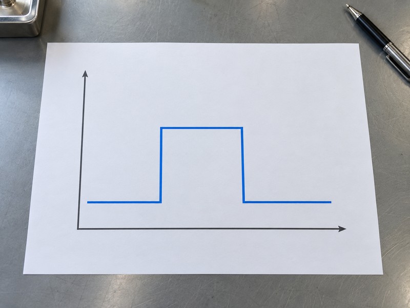
Compare the linked records. Retain the required initial position, specified departure response and restored condition with the identified point results. Record the applicable test procedure and acceptance criteria without assigning generic travel, timing or polarity to the symbol. The conceptual chart shows an abstract state sequence; it provides no measured result or acceptance threshold for the actual valve and system.
- Check references from valve tag through required system response.
- Use an authorized plan for physical movement and circuit testing.
- Link accepted results with the installed configuration and revisions.
Key takeaway: Verify both the document chain and its installed functional result through the responsible project process.
| Check | What you should confirm |
|---|---|
| Documents | Legend and linked references agree on asset and function |
| Testing | Authorized verification uses the selected acceptance criteria |
| Evidence | Results identify the actual valve and corresponding system point |
10. Who owns a symbol for butterfly valve with tamper switch?
The responsible project parties control a symbol for butterfly valve with tamper switch through the accepted legend and drawing revisions. Assign responsibility for the valve record, electrical schematic and point schedule so changes reach every affected document. A revised switch variant or intended position can alter the reporting definition even when the piping mark remains visually similar.
What should remain controlled after a revision?
Update the affected references. Retain approved changes, selected manuals, as-built identifiers and verification results with the document set. A symbol or drafting standard designation cannot establish product fire approval, panel compatibility or project acceptance by itself. RUITO can review an identified valve-assembly request and related product documents; the project’s responsible professionals retain legend, system design, commissioning and acceptance decisions.
- Assign owners for the linked drawing and system records.
- Review changed functions and update affected cross-references.
- Retain product approval evidence separately from drafting conventions.
Key takeaway: Control the symbol’s meaning through its linked records and assigned review responsibilities.
| Check | What you should confirm |
|---|---|
| Control | Accepted legend and document revisions have assigned owners |
| Change | Affected equipment, schematic and point records are updated |
| Approval | Product and system requirements retain their own supporting evidence |

Send RUITO your identified valve-assembly request, relevant legend excerpt, valve tag and existing product documents. We can review the requested valve configuration and clarify which assembly records your project team still needs. Contact us before purchasing from a symbol whose product identity or supervisory function remains unresolved.
FAQ
Q1: Can I reuse a symbol from another project’s CAD library?
Only after project review. Its legend meaning, operator notation and linked records must match the intended function on the current drawing set.
Q2: What’s the best reference for an unclear symbol?
Start with the accepted legend. Follow its notes and cross-references to the valve schedule and selected electrical schematic.
Q3: How do I know if the symbol means an electric actuator?
Check the operator notation. A position-monitoring mark alone cannot establish powered valve movement or a panel-command function.
Q4: Can I derive wire connections from the piping symbol?
No. Use the selected switch schematic and compatible input documentation for actual contact functions and electrical requirements.
Q5: How do I know if the point list matches the valve?
Trace the asset identity. Compare the valve tag, switch reference, actual input and accepted event description across the linked records.