
Choose an electric operated wafer butterfly valve after comparing its installed length, flange fit, disc clearance and operating limits with the alternative construction. If a replacement arrives with the wrong installed length or disc envelope, the actuator cannot make it fit. Compare the complete connection and operating configuration before choosing between the two constructions.
1. What is an electric operated wafer butterfly valve?
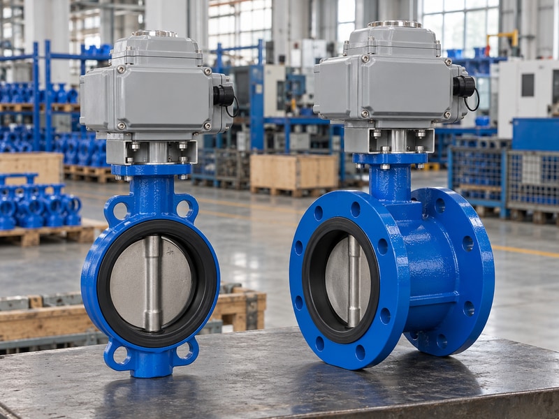
An electric operated wafer butterfly valve uses a compact valve body held between pipe flanges and a motor-driven actuator above its shaft. A double-flanged alternative has separate end connections on the valve body. The body style changes installation geometry; it does not by itself establish the seat, pressure rating or control capability.
Identify the connection before comparing performance
A wafer body commonly uses guiding features to help locate the valve between companion flanges. The project must still check the approved drilling, bolt arrangement and bore clearance. A double-flanged body connects at each end through its own flanges, with its own face-to-face requirement. Neither description substitutes for the specific assembly and connection drawings.
Compare the same duty when reviewing the two options. Different materials, disc geometry, offset or seat design may be offered within either broad body category. Use RUITO’s wafer valve information and the proposed configuration to identify what is actually being compared, rather than treating connection style as a performance grade.
- Identify the body connection accurately.
- Review the complete drawing for each option.
- Keep seat and performance comparisons separate.
| Feature | Wafer arrangement | Double-flanged arrangement |
|---|---|---|
| Connection | Between companion flanges | Valve has end flanges |
| Installed geometry | Compact body arrangement | Own face-to-face requirement |
| Performance rating | Selected model and materials | Selected model and materials |
2. How does face-to-face length affect replacement?
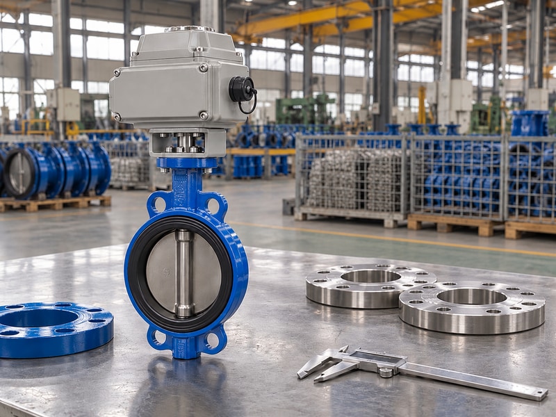
An electric operated wafer butterfly valve must match the installation’s approved space and connection arrangement. Replacing a double-flanged unit with a thin wafer body can leave a gap, while the reverse may require more space than the pipework allows. Nominal diameter does not determine installed length.
Measure the existing arrangement against the new drawing
Obtain the original valve dimensions and a site survey where replacement work depends on existing pipework. Check the distance between mating faces, available pipe movement and any dismantling arrangement. Do not assume two catalog valves share a face-to-face series simply because both have the same DN and pressure class. The exact construction and drawing govern the comparison.
Include the actuator envelope and access when planning the replacement. A shorter body does not automatically create enough space for a larger drive enclosure. If pipework modification is proposed, have the project designer review support, alignment and loads. Compare the double-flanged valve arrangement with the existing installation before ordering either alternative.
- Confirm the distance between mating faces.
- Check the actual dimensional series.
- Include actuator and maintenance clearances.
| Dimension | Obtain from | Use |
|---|---|---|
| Installed length | Site and approved valve drawing | Connection fit |
| Enclosure envelope | Complete assembly drawing | Access and interference review |
| Available movement | Pipework and dismantling design | Replacement planning |
3. Which flange details need to match?
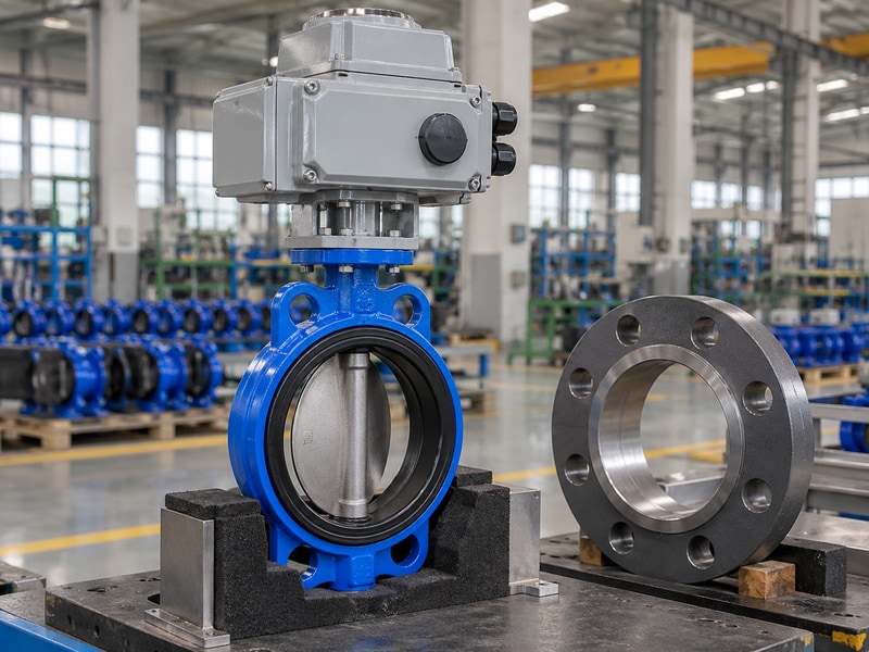
Match an electric operated wafer butterfly valve to companion flange drilling, bore, face arrangement and the approved pressure class. Similar nominal sizes can hide different bolt circles or internal clearances. A body that can be placed between flanges is not necessarily ready for tightening or full disc travel.
Check both the bolt pattern and the inside opening
Ask for the valve’s approved companion flange requirements and compare them with the piping specification. Check bolt access around the body and actuator support. For the double-flanged option, confirm the standard and arrangement at each end. Do not combine an assumed drilling pattern with an unrelated pressure-temperature rating from another product configuration.
Review the internal bore and any lining or pipe wall that could enter the disc’s opening envelope. Reducing flanges and thick-wall pipe deserve particular attention where the drawing shows limited clearance. The project should resolve the fit before installation, rather than relying on the motor to reveal interference during its initial powered stroke.
- Match drilling and face arrangement.
- Check bore clearance through the full travel.
- Confirm the exact rated connection configuration.
| Flange item | Check | Possible mismatch |
|---|---|---|
| Drilling | Bolt circle and holes | Bolts cannot align |
| Bore | Disc opening envelope | Disc contact |
| Face arrangement | Approved joint detail | Poor sealing or seat distortion |
4. Do the two body styles need different gaskets?
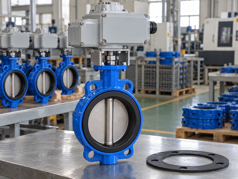
An electric operated wafer butterfly valve needs the gasket arrangement specified for its exact seat and joint design. Some resilient-seat constructions form the flange seal through the seat itself. Other valves use separate gaskets. Body style alone cannot settle the correct joint detail or tightening method.
Follow the seat and connection instructions
Check whether the approved instructions permit or require added gaskets. Adding one where it is not intended can change seat compression or joint behavior. Lined valves have further requirements for protecting liner flares and controlling clamping. A familiar site gasket practice should not override the supplied valve’s approved installation arrangement.
Compare joint preparation, bolt access and tightening instructions for the proposed double-flanged option as well. Keep pipe faces aligned and support the installation as designed. If a leak appears after assembly, review the joint and seat arrangement under safe isolation before applying additional force. More bolt load is not a substitute for the correct parts and fit.
- Confirm whether separate gaskets are specified.
- Protect integral seats and liner flares.
- Use the approved tightening procedure.
| Joint question | Evidence | Installation decision |
|---|---|---|
| Integral seat seal | Valve instructions | Use the specified joint arrangement |
| Separate gasket | Approved material and geometry | Match the connection design |
| Lined flare | Liner-specific instructions | Control clamping and protection |
5. Does a flanged body automatically offer higher performance?
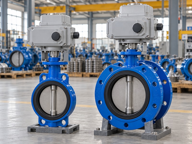
A double-flanged alternative to an electric operated wafer butterfly valve must be judged by its own design, materials and documented ratings. A flange connection does not automatically establish higher pressure, temperature or sealing performance. Different seat and offset designs may explain a performance difference that the connection name alone cannot.
Compare like-for-like operating limits
Use pressure and temperature together for each offered configuration. Check allowable closing differential, direction and the selected seat leakage criterion. RUITO offers conventional concentric water valves, large double-offset valves and lined valves as separate configurations. Their size ranges and service boundaries should remain attached to their own designs rather than being merged into one broad product claim.
Capacity and torque also need model-specific information. Two valves of the same DN may have different effective flow areas, disc profiles and operating loads. Ask for the curves and torque data needed for the project. If the duty is simply isolation, confirm that requirement; if throttling is needed, assess the flow and control behavior separately.
- Compare the same process duty.
- Keep ratings attached to each configuration.
- Request capacity and torque where needed.
| Performance item | Comparison basis | Avoid assuming |
|---|---|---|
| Pressure-temperature | Same stated operating condition | Connection name sets the rating |
| Shutoff | Direction and specified criterion | Every seat seals identically |
| Capacity and torque | Selected model data | Same DN means same behavior |
6. What changes in actuator selection?
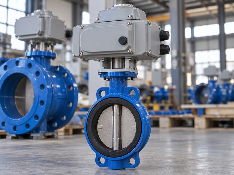
Select the actuator for an electric operated wafer butterfly valve or a double-flanged valve from the actual valve torque requirement and assembly limits. Connection style does not determine motor output. Seat design, disc geometry, differential pressure and operating duty can change the required torque even at the same nominal diameter.
Review the complete drive interface
Check breakaway, running and seating requirements using the valve supplier’s data. Compare available drive output at its stated conditions and the assembly’s maximum permitted input. The bracket, coupling and shaft must have the required engagement and strength. A mounting flange designation covers only one part of the mechanical fit.
Include enclosure clearance, support, manual operation and control function. A project choosing a larger double-flanged valve may need a different actuator arrangement, but that decision comes from the actual load and geometry. Record protection settings and integrated function tests after assembly so the delivered unit corresponds to the approved mechanical and electrical package. Identify the project-specified ISO 5211 interface and review the support-to-valve attachment separately.
- Use duty-specific valve torque.
- Check both available and permitted input.
- Verify coupling and enclosure clearances.
| Drive input | Wafer option | Flanged option |
|---|---|---|
| Required torque | Selected valve data | Selected valve data |
| Mounting and coupling | Approved interface | Approved interface |
| Controls and duty | Project requirement | Project requirement |
7. Can either arrangement be used at a pipe end?
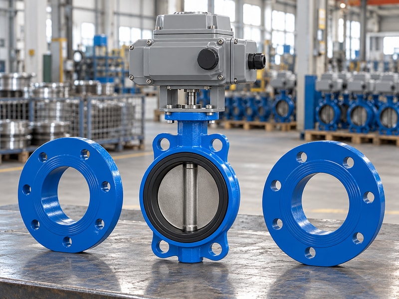
An electric operated wafer butterfly valve should not be assigned end-of-line duty without the selected configuration’s explicit approval. A double-flanged body also needs its declared end conditions and pressure limits checked. The existence of bolt holes or a flange does not establish every possible unsupported or one-sided pressure condition.
Separate connection form from permitted end conditions
Define the intended pipe arrangement and which side may be removed or depressurized. Ask for the permitted differential pressure, direction, temperature and mechanical loading for that state. If a lugged alternative is proposed, its thread engagement and independently qualified end conditions need review. Do not transfer a rating from a different size or body design.
Plan maintenance access and isolation through the project design. Removing downstream pipework can change restraint and expose a disc or joint to loads unlike normal two-sided installation. Review supports and the approved work procedure before selecting the body. RUITO’s lug valve information can identify a construction for further assessment, with limits confirmed for the specific order.
- Describe the exact end-of-line arrangement.
- Confirm pressure, direction and support limits.
- Use an approved maintenance isolation plan.
| End-condition item | Confirm | Evidence |
|---|---|---|
| One side removed | Permitted configuration | Model-specific approval |
| Differential pressure | Direction and temperature limits | Declared end rating |
| Mechanical restraint | Support and connection loads | Project installation review |
8. How do maintenance and handling affect the choice?
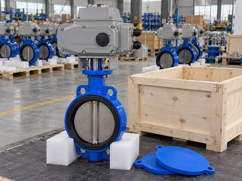
Compare an electric operated wafer butterfly valve and a double-flanged option for the access, support and removal method your site can provide. The lighter or shorter catalog option may still be difficult to remove from a constrained pipe run. Plan the complete maintenance arrangement before selecting the connection.
Account for the installed assembly
Check room to withdraw bolts, open the actuator enclosure and use the approved manual operating arrangement. Identify how the valve and actuator mass will be supported during installation or removal. Follow designated lifting points; do not lift the assembly by a cable gland or assume the actuator housing is a lifting lug. The removal plan must consider the complete package.
Confirm spare-part access and storage requirements for the selected seat and drive. A change of body style may change spare parts and installation instructions even where process duty stays constant. Compare the documented maintenance needs with available site resources. Record those requirements in the selection review rather than leaving the maintenance team to solve them after delivery.
- Check bolt withdrawal and enclosure access.
- Plan support and approved lifting points.
- Match spares and instructions to the chosen version.
| Maintenance task | Space or equipment needed | Selection check |
|---|---|---|
| Valve removal | Pipe movement and handling support | Practical removal route |
| Actuator service | Enclosure and operating access | Unobstructed working space |
| Spare replacement | Correct parts and instructions | Configuration-specific support |
9. What should the final comparison record show?
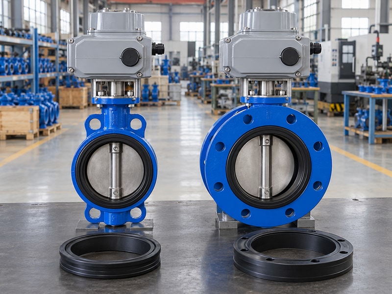
The final comparison for an electric operated wafer butterfly valve should show why the selected connection fits the installation and meets the duty. Record dimensions, materials, operating limits, drive requirements and maintenance access. A choice based on price or body thickness alone leaves engineering differences unresolved.
Close the drawing review before ordering
Place the offered wafer and double-flanged configurations against the same project requirements. Note each deviation and its effect on piping, supports, controls or acceptance. If a proposed replacement needs pipework changes, include the project approval and schedule impact. Keep the accepted drawing and material versions with the purchasing documents.
Agree on inspection records and integrated function testing for the selected assembly. RUITO can review the companion flange details and operating data to define a proposed configuration. Use the technical enquiry page with the installation information, then approve the final connection and drive drawings before the order moves into manufacture.
- Compare both options against one duty sheet.
- Record installation and maintenance deviations.
- Freeze the selected drawings and test scope.
| Decision area | Required basis | Final record |
|---|---|---|
| Installation | Dimensions and end conditions | Approved connection drawing |
| Operation | Materials, ratings and drive | Accepted data sheet |
| Handover | Tests, instructions and spares | Final document index |
Send RUITO the companion flange details, installed space, medium and operating duty. We can compare wafer and double-flanged arrangements against those inputs and identify the drawing checks needed. Contact us before selecting a replacement from nominal pipe size alone.
10. What else should you check before ordering?
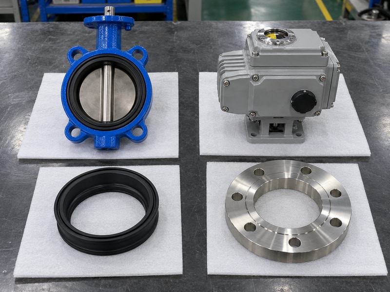
For electric operated wafer butterfly valve, resolve these remaining questions against the approved package and site conditions.
Q1. Can I replace a flanged valve with a wafer valve?
Only after checking installed length, companion flanges, disc clearance, supports and permitted end conditions. The project may need an approved piping change. Matching nominal diameter alone is insufficient.
Q2. Is a wafer valve always lower pressure?
No. Compare the documented ratings of the exact configurations at the required temperature and closing differential. The connection name alone does not establish pressure or seat capability.
Q3. What's the best way to check disc clearance?
Compare the valve’s approved opening envelope with the actual companion flange and pipe bore, including linings and wall geometry. Resolve interference before powered travel or final installation.
Q4. Can I add gaskets to stop a flange leak?
Use only the joint arrangement approved for the selected seat and connection. Added gaskets can distort some integral-seat designs. Investigate fit, alignment and installation conditions under safe isolation.
Q5. Does the same actuator fit both constructions?
It may, but the actual valve torque, permitted input, mounting, coupling, travel and controls must be reviewed. Do not transfer a drive solely because the two valves share a diameter.