
You avoid costly electric butterfly valve mistakes by specifying the valve, drive, mounting parts and controls as one tested assembly. An electric resilient seat flanged butterfly valve can fit the pipe yet fail its first functional check because the coupling, torque settings or control logic do not match the duty. Finding those mismatches after installation means reopening drawings, changing wiring or removing equipment from a finished line.
Start with the actual fluid, operating envelope and maximum closure differential. Then freeze the mechanical interface, electrical requirements and acceptance records before purchasing. The following checks give procurement and engineering a common basis for reviewing the complete assembly.
1. Which electric resilient seat flanged butterfly valve fits?
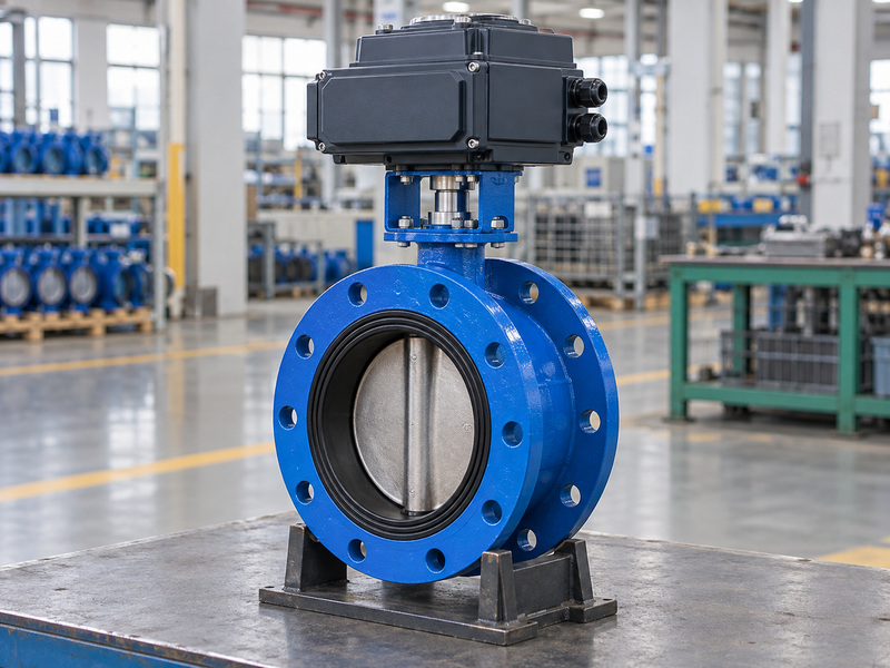
The correct electric resilient seat flanged butterfly valve matches the fluid, temperature, working pressure and closure differential in the same approved configuration. RUITO’s concentric double-flanged water-duty range covers DN50–600 and PN10/16; general clean-water applications use EPDM within their stated temperature and pressure limits. The electrical drive does not expand those limits.
For clean-water isolation, the stated application range is 5–60°C, with the allowable working pressure taken from the selected model’s pressure–temperature relationship. At 20°C, the relevant PN10 or PN16 configuration has a 10 or 16 barg upper boundary. Cycling frequency, transient pressure and allowable closure differential still need separate entries on the data sheet.
Which material questions need written answers?
List additives, cleaning fluids and abnormal temperatures alongside the normal medium. The PTFE-lined butterfly valve belongs to a separate chemical-service configuration; adding an electric drive to an EPDM water valve does not create that configuration. Ask the supplier to return deviations before selecting an actuator.
| Duty input | Information to provide | Review outcome |
|---|---|---|
| Fluid | Composition and cleaning agents | Approved wetted materials |
| Temperature | Normal and limiting values | Matching pressure boundary |
| Pressure | Working and transient conditions | Model-specific acceptance |
| Closure duty | Differential in each direction | Seat and drive requirements |
Keep the accepted duty sheet with the purchase order so later substitutions can be assessed against the same conditions.
2. How should the complete drive assembly be defined?
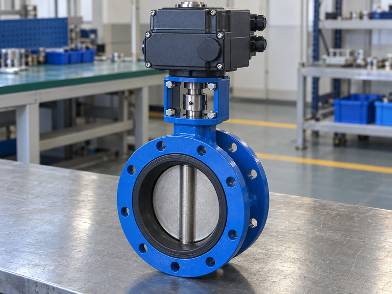
Define an electric resilient seat flanged butterfly valve as the valve, actuator, bracket, coupling and specified accessories under one controlled assembly drawing. A quotation for a bare valve plus an actuator leaves responsibility for alignment, fastening and final adjustment unresolved. Identify who supplies, assembles and tests every connecting part.
The general arrangement drawing should show mounting orientation, overall height, cable access and manual override clearance. Check that the actuator can be removed without dismantling adjacent equipment where maintenance requires it. Include the assembly’s handling arrangement; the actuator housing should not become an improvised lifting point.
What belongs in the approved assembly record?
Require a bill of materials that names the seat compound, shaft, coupling and drive alongside the pressure-containing parts. Link the drawing revision to the wiring diagram and actuator settings. A change to bracket height can affect access, while a different coupling can change engagement and backlash despite an unchanged external appearance.
| Assembly item | Evidence to review | Mismatch to resolve |
|---|---|---|
| Valve and drive | Named configuration | Unapproved substitution |
| Bracket | Drawing and fixing details | Misalignment or interference |
| Coupling | Bore, engagement and retention | Loose or incomplete engagement |
| Accessories | Wiring and mounting records | Incompatible feedback or access |
Approve the assembled envelope before the equipment designer releases surrounding pipework and supports.
3. How do shaft, coupling and torque checks connect?

Size an electric resilient seat flanged butterfly valve drive from the valve’s starting, running and seating torque requirements, then check the strength of the entire transmission path. The required torque depends on size, seat condition, temperature, fluid and closure differential. A single catalogue torque value without those conditions cannot settle the selection.
Ask for the actuator’s available output under the specified supply and operating conditions, the sizing allowance and the permitted torque settings. More output can damage a shaft or coupling if the assembly lacks suitable limits. Document the allowable loads for each interface rather than treating the actuator’s maximum output as an acceptable valve load.
Which interfaces need dimensional verification?
Check shaft geometry, coupling engagement, keys or drive flats, retaining parts and bracket alignment against the approved drawings. If the project changes to a lug butterfly valve, repeat these checks for the selected assembly rather than carrying over the flanged valve’s torque and mounting assumptions.
| Torque or interface check | Required basis | Acceptance evidence |
|---|---|---|
| Starting torque | Stated duty and seat condition | Valve torque record |
| Available output | Specified supply conditions | Actuator selection sheet |
| Load limitation | Shaft and coupling capacity | Approved settings |
| Mechanical fit | Actual interface dimensions | Assembly inspection |
Resolve an unexplained torque margin before ordering; correcting it after assembly may require a different drive or transmission part.
4. How should power and control signals be specified?
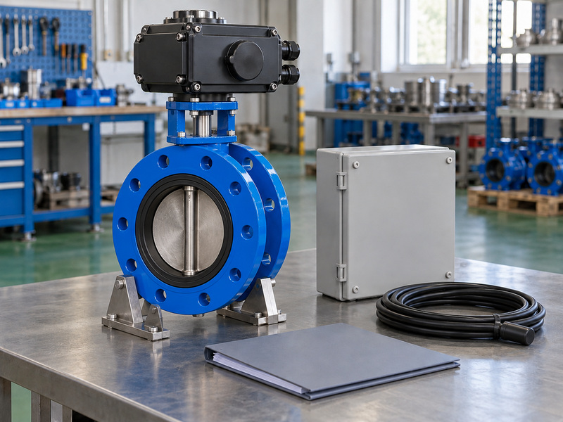
Specify an electric resilient seat flanged butterfly valve with separate definitions for motor power, command inputs, position feedback and fault indication. A control signal value does not identify the motor supply. An open/closed indication does not establish that the actuator accepts proportional position commands.
The purchaser should provide the available supply, frequency where relevant, permitted variation and control system interface. State whether the duty is isolation or modulation, along with the expected operating frequency. The supplier must confirm the selected actuator’s capability for that duty rather than infer it from a general product description.
Which control details cause avoidable commissioning work?
Record terminal assignments, contact arrangements, signal behavior and local/remote selection in an approved wiring diagram. Identify how the control system distinguishes a travel command, confirmed position and a fault. Specify the required enclosure and environmental performance from actual installation conditions, and request supporting documents for the selected actuator; no universal rating follows from electric operation.
| Electrical function | Purchaser defines | Supplier confirms |
|---|---|---|
| Drive power | Available supply and variation | Compatible actuator selection |
| Commands | Isolation or positioning logic | Input arrangement |
| Feedback | Required position information | Output type and terminals |
| Faults | Required alarms and response | Available indication and settings |
Have the controls engineer sign off the wiring revision before cables and panels are finalized.
5. What happens after power or signal loss?
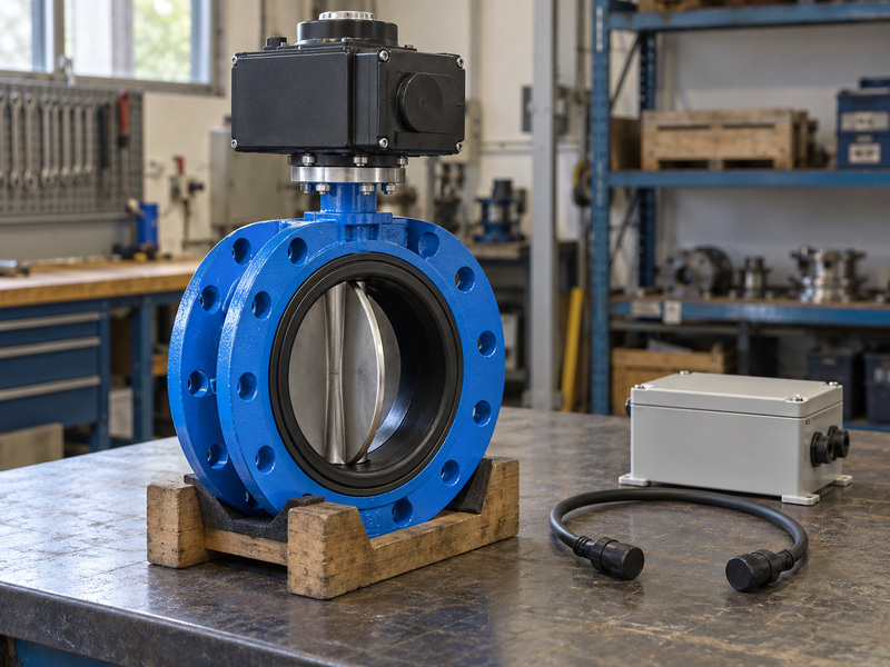
An electric resilient seat flanged butterfly valve moves to a defined failure position only when the selected actuator and control arrangement provide that function. Removing electrical power does not automatically close the valve. The actual response depends on the drive design, any stored energy and the implemented logic.
Write separate requirements for loss of drive power, loss of command signal and restoration of power. A signal-loss action can differ from a complete power-loss action because the motor may still have power in the first condition. Specify whether restoration should permit automatic movement or require a deliberate reset under the system’s operating rules.
How can you verify the agreed response?
Use an approved functional procedure that identifies the starting position, removed input, available energy and expected indication. If a battery or other stored-energy system is included, define its inspection and maintenance requirements with the supplier. Record the observed travel and indications on the actual assembly rather than accepting a generic fail-safe label.
| Event | Requirement to define | Check to record |
|---|---|---|
| Drive power loss | Required position or hold behavior | Actual movement and indication |
| Command loss | Response with drive power present | Input fault and travel |
| Power restoration | Restart permission | Automatic or reset behavior |
| Stored-energy fault | Required alarm or limitation | Available diagnostic response |
The process designer must select the required response from the system duty before the supplier configures the actuator.
6. How should travel, limits and operating time be set?
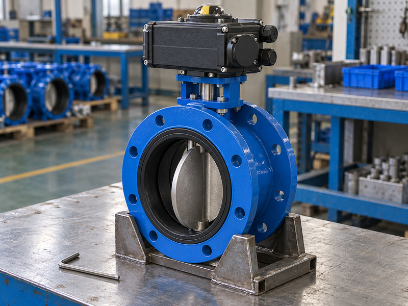
Set an electric resilient seat flanged butterfly valve to its approved opening and closing positions, then verify the actuator’s limits, torque settings and position indication together. A butterfly disc has a defined operating travel; unrestricted rotation is not an acceptable installation assumption. Mechanical stops and electrical limits must follow the assembly instructions.
Check that the open indication corresponds to the intended disc position and that closing achieves the specified seal without excessive loading. Establish operating time with the piping designer where closure speed can affect transients. Changing motor speed or control timing solely to satisfy a convenient cycle time can create a different system response.
What changes when modulation is required?
Positioning duty needs an actuator suitable for the specified starts and control pattern, plus valve data for the intended operating range. Intermediate disc angle alone does not guarantee a particular flow. Ask for the relevant flow coefficient information and evaluate pressure drop, noise and stability against actual fluid conditions.
| Adjustment | Verify against | Record at acceptance |
|---|---|---|
| Open limit | Approved disc position | Indication and physical travel |
| Closed limit | Seat and drive instructions | Seal and stop behavior |
| Torque setting | Transmission load limits | Final setting values |
| Operating time | System transient assessment | Measured travel time |
Keep final settings in the handover record so replacement drives can be configured consistently.
7. How do you prevent flange installation damage?
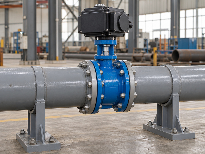
Install an electric resilient seat flanged butterfly valve between compatible, aligned flanges in the closed-pipe arrangement covered by its approved drawing and instructions. Check drilling, face-to-face length, flange faces and adjoining bore before bringing the assembly into position. Bolts should not be used to pull misaligned pipework onto the valve.
Double-flanged and wafer butterfly valve installations have different body and connection arrangements. Do not transfer a wafer face-to-face dimension or fastener schedule to a double-flanged valve. Verify disc opening clearance against actual adjoining components, including reducers and any projecting pipe lining.
Which installation details require the supplier’s instructions?
Follow the specified disc position during insertion, gasket requirements, tightening sequence and bolt loading. Some seat designs form part of the flange sealing arrangement, so adding a gasket without checking can alter the assembly. Keep weld debris and foreign material out of the seat, and support the pipe and actuator as the installation design requires.
| Installation check | Compare | Problem prevented |
|---|---|---|
| Flange drilling | Approved valve and pipe drawings | Forced bolt alignment |
| Disc clearance | Actual adjoining bore | Mechanical interference |
| Sealing arrangement | Valve installation instructions | Distorted seat or face seal |
| Pipe support | Approved installation layout | External loading on assembly |
Complete a controlled travel check under the approved installation procedure before admitting service fluid.
8. Which tests prove the assembled valve works?
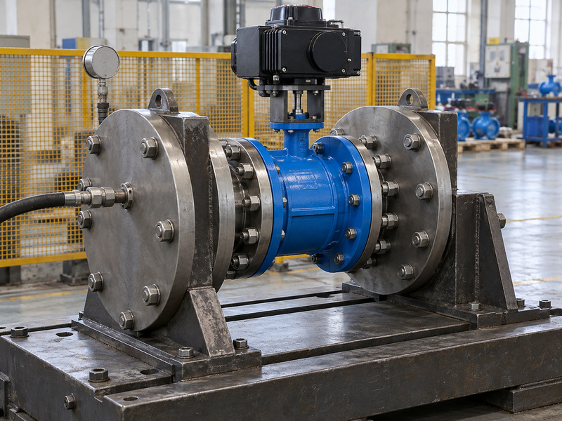
Accept an electric resilient seat flanged butterfly valve using pressure records and functional checks that identify the delivered valve and drive assembly. A bare-valve pressure report cannot confirm wiring, limits, feedback or power-loss behavior after mounting. Define which tests occur before assembly and which are repeated on the finished unit.
Choose EN 12266-1 or the contractually selected pressure-testing route, with the applicable procedure and acceptance criteria stated. The official ISO 5208 industrial valve pressure-testing resource identifies another contract option. Its presence in a quotation still requires an agreed test scope, pressure, duration, direction and leakage criterion.
What should the final report identify?
Require the product ID, drawing revision, test medium, instrument identification and results. RUITO’s stated ambient PN16 water-duty checks include 24 bar shell and 17.6 bar soft-seat closure testing where the selected configuration and seat differential rating support that procedure. Those pressures are inspection conditions, not higher operating ratings.
| Acceptance activity | Evidence needed | Scope boundary |
|---|---|---|
| Shell and closure | Product-linked test record | Approved pressure procedure |
| Full travel | Final assembly function record | Correct mechanical positions |
| Commands and feedback | Wiring revision and results | Specified control functions |
| Failure response | Approved event sequence | Selected drive arrangement |
Close discrepancies against the same product ID before authorizing shipment.
9. What should procurement freeze before release?
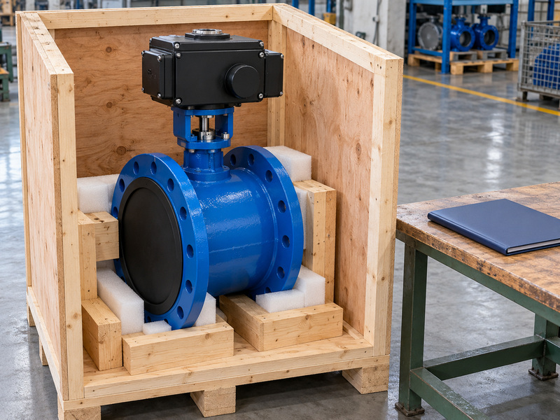
Procurement should release an electric resilient seat flanged butterfly valve only after the duty, assembly revision, inspection scope and delivery documents agree. The purchase order needs more than size, PN and the word electric. Include the accepted deviations so neither party has to reconstruct technical decisions from scattered correspondence.
Ask for the installation and maintenance instructions, final settings, wiring diagram and accurate spare-parts identification. Confirm whether cables, glands, local controls and commissioning support are included or supplied by others. Packaging should protect flange faces, the drive and accessories while preserving product identification.
How should delivery and later changes be controlled?
Separate technical approval, material readiness, assembly, witness inspection and factory release from transport and destination arrival. Require written approval for changes to the seat, shaft, coupling, actuator or wiring revision. For an assembly review, contact us with the fluid data, closure differential, flange drawing and required control behavior.
| Release item | Freeze in the order | Confirm before dispatch |
|---|---|---|
| Technical scope | Duty and approved assembly | Matching product identification |
| Inspection | Procedure and witness points | Completed records |
| Electrical supply | Drive and accessory scope | Final wiring and settings |
| Delivery | Release and shipping milestones | Packing and document status |
Authorize substitutions only after their mechanical, electrical and duty effects have been reviewed.
10. What do buyers ask before placing an order?
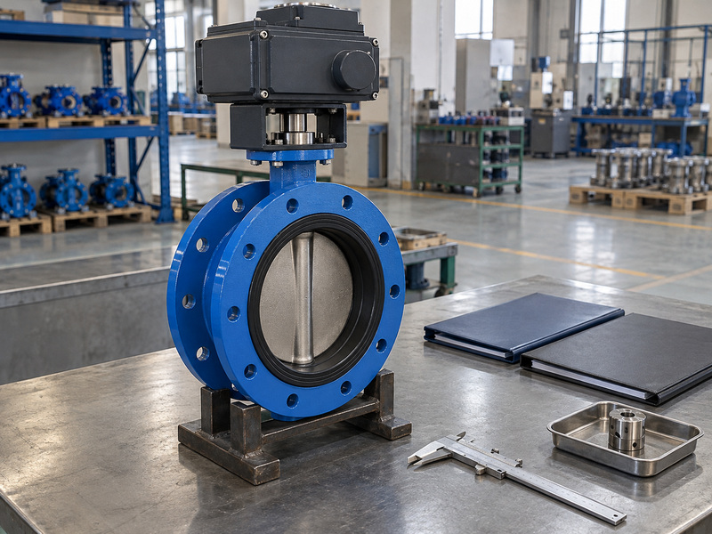
Buyers should resolve the following electric resilient seat flanged butterfly valve questions before the assembly drawing is frozen.
Q1. Can I assume the valve closes when power fails?
No. Specify the required response and verify that the selected actuator, energy arrangement and controls provide it under the agreed conditions.
Q2. Can I choose an actuator from pipe size alone?
No. Use the valve’s duty-specific torque requirements, available actuator output and allowable shaft, bracket and coupling loads.
Q3. How do I know if the flanges will fit?
Compare approved drawings. Confirm drilling, face-to-face length, flange faces and the actual bore clearance through the disc’s full operating travel.
Q4. Is a pressure test enough for final acceptance?
No. The finished assembly also needs the specified travel, command, feedback and failure-response checks with product-linked records.
Q5. Can I use one electrical specification for every project?
Only where the requirements match. Confirm supply, control interface, operating duty, environment and required documentation for each selected assembly.