
Choose an electric triple eccentric butterfly valve by matching the complete assembly with the process duty, available power, and required control response. A motor that turns the shaft on a workshop bench may still miss the closing load in service. Request a traceable selection covering the valve, actuator, coupling, bracket, settings, and acceptance tests before approving the purchase.
1. What defines an electric triple eccentric butterfly valve?
An electric triple eccentric butterfly valve combines a triple-offset valve with an electrically powered operating assembly. The offsets describe the valve's geometry; they do not establish motor duty, failure response, or control capability. Confirm the proposed valve construction and actuator together, because a suitable body and a suitable motor can still make an unsuitable assembly.
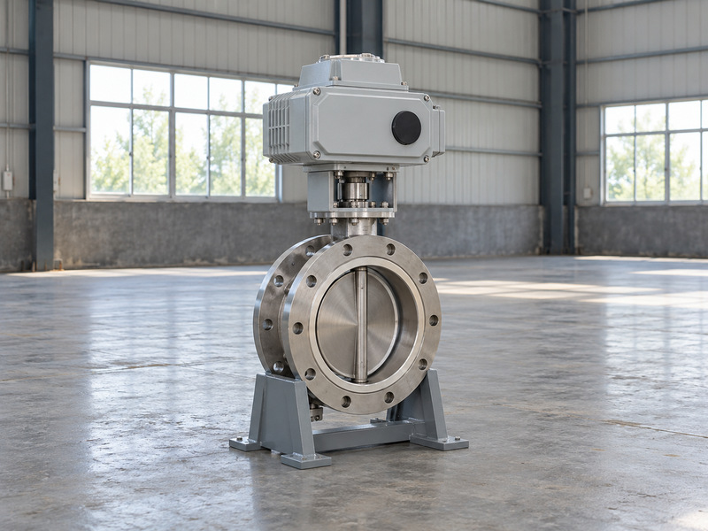
Define the purchased assembly
Your enquiry should name the fluid, operating temperature and pressure, closing differential, pressure direction, and required leakage criterion. Include frequency of operation and whether the valve isolates or regulates flow. A general electric-actuation description cannot establish that a valve suits continuous control duty.
Request an assembly drawing with the actual drive arrangement. A direct part-turn actuator and a motor driving a separate gearbox create different interfaces, maintenance access, and torque calculations. Identify which supplier takes responsibility for the assembled function and resolves any conflict between the valve and actuator instructions. Keep optional accessories separate from items required for the quoted assembly to perform its stated duty.
- Freeze the service and shutoff requirements.
- List every supplied mechanical and electrical component.
- Assign responsibility for assembly testing.
| Purchase item | Required definition |
|---|---|
| Valve | Construction and operating limits |
| Drive | Selected actuator and any gearbox |
| Assembly | Interfaces, settings, and test scope |
2. How should you compare required and available torque?
Compare required valve torque with available actuator output throughout the relevant operating stroke. An electric triple eccentric butterfly valve needs enough output for opening, running, and final seating under its specified conditions. The torque required by the valve, output available from the drive, and load allowed by the components are separate values.
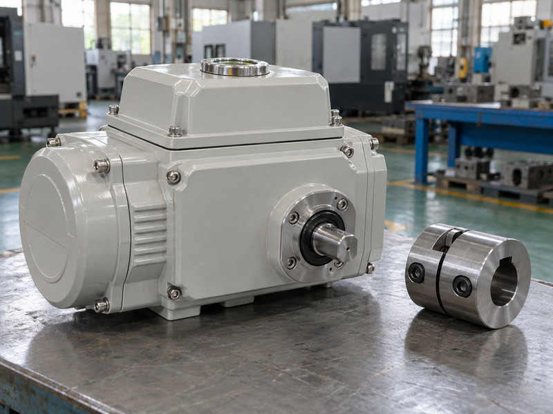
Keep three torque limits separate
Ask for valve torque data covering the specified differential, direction, temperature, packing condition, and relevant operating cases. Have the supplier state the sizing margin and its basis. A single catalogue output figure cannot show whether the selected drive satisfies every point of that duty. Include reopening after a prolonged closed period if that condition belongs to the service specification.
Check the shaft, keys or drive flats, coupling, bracket, and gearbox against their allowable loads. Oversizing may create an overload path even when it solves an output shortfall. Review the protection settings and possible peak output together; a torque limit in software does not replace the mechanical design review.
- Request opening, running, and seating requirements.
- Compare output at the specified supply conditions.
- Record allowable loads and protection settings.
| Torque term | Meaning |
|---|---|
| Required | Load needed to operate the valve |
| Available | Output the selected drive can deliver |
| Allowable | Load each component can accept |
3. Which electrical supply conditions must you specify?
Specify the supply at the actuator terminals, including its minimum operating voltage and starting conditions. An electric triple eccentric butterfly valve cannot be selected from nominal plant voltage alone. Cable length, starting demand, supply tolerances, and simultaneous operation can affect the conditions reaching the motor.
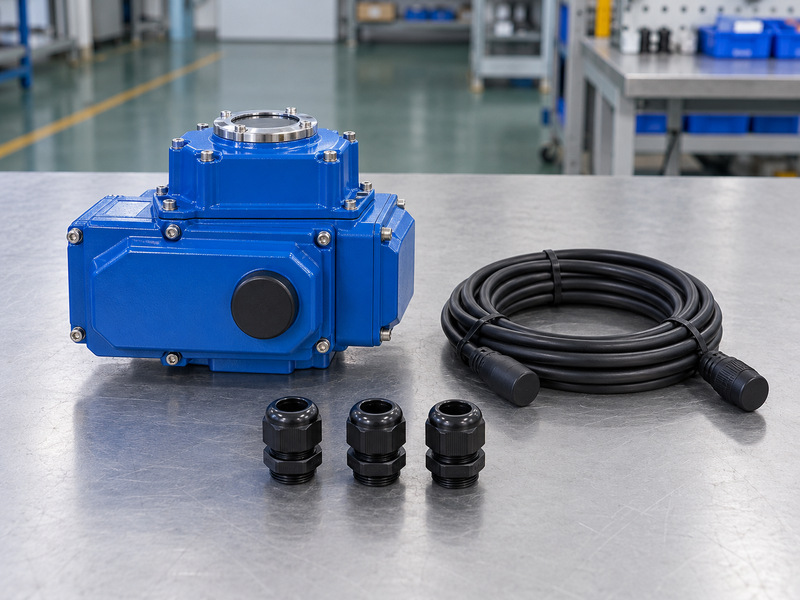
Check starting and operating conditions
Provide the available phase arrangement, voltage, frequency, and control power. Request the selected motor's current data and permitted supply tolerances. Have the electrical engineer check the cable and protection arrangement against those values rather than assuming a neighbouring motor has comparable starting behaviour. Obtain the final terminal diagram before the contractor orders cables or assigns control-panel terminals.
If a backup supply forms part of the design, confirm its compatibility, capacity, and required number of operations. A small battery that maintains position indication may have no capacity to drive the valve. Keep indication backup and operating-energy backup separate on the electrical schedule.
- State minimum terminal supply during starting.
- Confirm motor and control power requirements.
- Identify backup power loads individually.
| Supply question | Evidence to request |
|---|---|
| Will it start? | Motor data and terminal supply check |
| Will it complete travel? | Selected operating envelope |
| What survives power loss? | Defined backup functions |
4. Does the actuator suit the operating duty?
The actuator must suit the actual cycling, starts, running time, and ambient conditions. An electric triple eccentric butterfly valve used for occasional isolation has a different duty from one receiving repeated position corrections. A short operating time in a brochure does not establish suitability for repeated service.
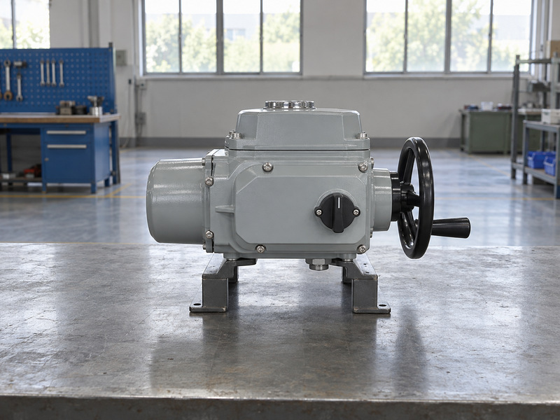
Describe how the valve will operate
Give the supplier the expected operations during normal service, startup, shutdown, and testing. For regulating duty, include the required positioning behaviour and frequency of corrections. Ask whether the selected motor, controls, and valve construction suit those demands at the actual ambient temperature. A shutdown sequence may demand several successive operations even when routine service involves very few cycles.
Request the permitted duty and any cooling or operating restrictions in writing. A thermal trip protects equipment within its design; a process that repeatedly reaches that trip still has an application problem. Review stroke time with the system engineer, especially where closure can create pressure transients.
- Describe normal and exceptional operating sequences.
- Check duty at the specified ambient conditions.
- Agree a stroke time the process can tolerate.
| Duty item | Selection check |
|---|---|
| Repeated starts | Motor and control rating |
| Position corrections | Regulating suitability |
| Stroke time | Actuator capability and system response |
5. How do coupling and bracket details affect operation?
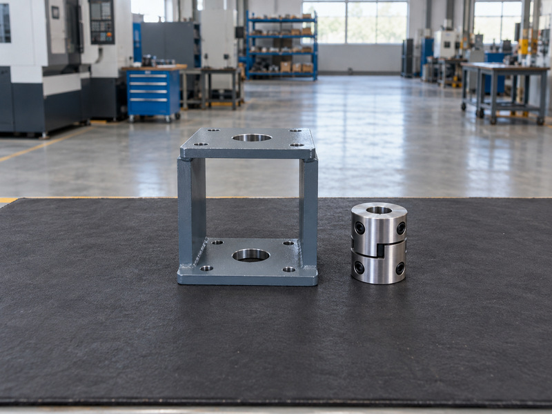
A correctly aligned, adequately rated connection carries torque without unwanted shaft loading. The electric triple eccentric butterfly valve assembly needs matching drive dimensions, engagement, orientation, and support. A mounting pattern that appears compatible does not prove the complete interface fits or carries the specified load.
Review the assembled interface
Check the valve shaft projection, coupling bore, keys or flats, fasteners, and actuator output against the approved drawing. Confirm engagement and clearance without forcing the drive into position. A coupling that bottoms out can impose axial load even when its bolt pattern lines up. Ask for interface dimensions whenever the actuator and valve come from different supply packages.
Include the actuator's weight, mounting orientation, manual-operation clearance, and removal route. When comparing body arrangements, use RUITO's documented flanged butterfly valve configurations as a separate connection comparison; that page does not establish a triple-offset supply range.
- Confirm dimensions and allowable interface loads.
- Check alignment before securing the drive.
- Provide support and maintenance access as specified.
| Interface detail | Possible consequence of a mismatch |
|---|---|
| Bore and engagement | Lost motion or concentrated stress |
| Alignment | Unwanted shaft and bearing load |
| Clearance | Restricted operation or maintenance |
6. How should closing torque and travel stops be set?
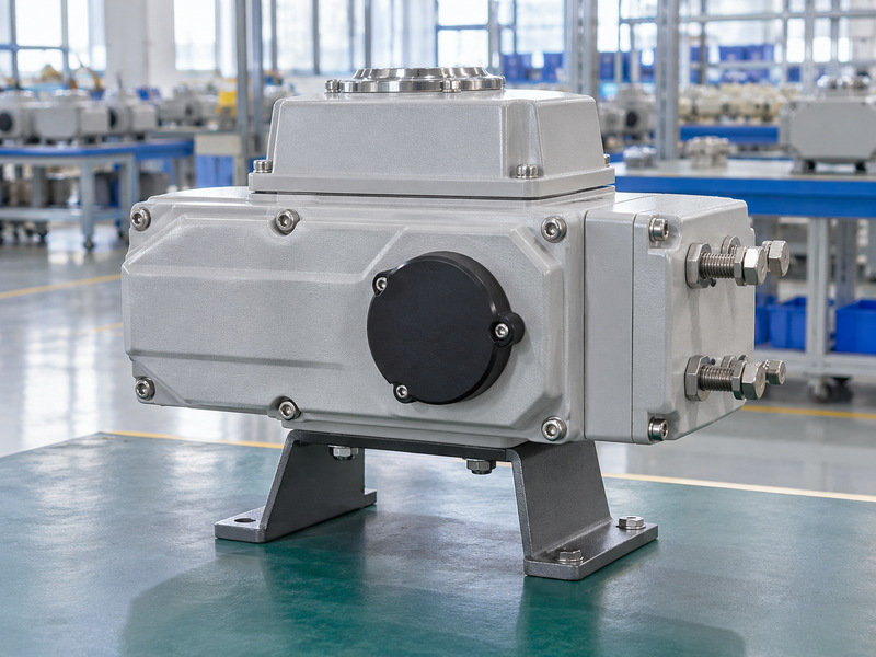
Set closing action, torque protection, and travel stops from the approved valve and actuator instructions. An electric triple eccentric butterfly valve may require torque seating, but the exact method belongs to its selected design. Generic percentages, stop-bolt turns, or copied settings from another assembly can prevent closure or overload components.
Obtain a coordinated setting procedure
Require the supplier to state which function stops normal closing and how the mechanical stops relate to that action. Check opening limits too. Where a gearbox sits between motor and valve, its stop arrangement must follow the same approved operating sequence. Record who may change settings and how the revised configuration becomes part of the handover documents.
An indicated closed position can occur before the sealing surfaces receive the required load. Raising torque indiscriminately can hide an obstruction, incorrect stop, or assembly fault. Resolve unexpected behaviour through the manufacturer's procedure and repeat the specified functional and closure checks after an authorised adjustment.
- Obtain model-specific setup instructions.
- Record approved torque and limit settings.
- Recheck function after any setting change.
| Setting | Purpose to confirm |
|---|---|
| Closing action | Correct termination of normal closure |
| Torque protection | Controlled load within approved limits |
| Travel stops | Correct mechanical travel boundary |
7. Which commands and feedback signals do you need?
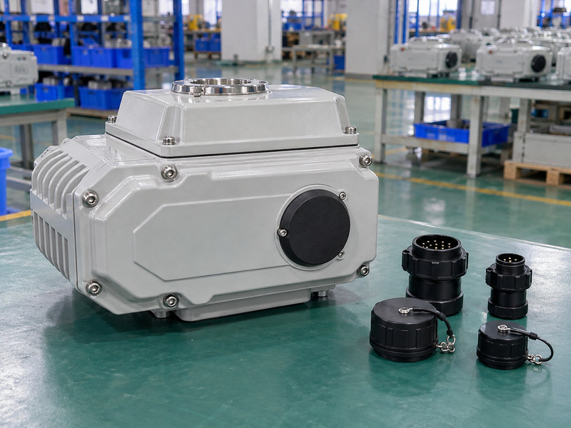
Define commands, permissives, alarms, and feedback around the intended control sequence. An electric triple eccentric butterfly valve may accept discrete commands or a positioning demand, depending on its selected controls. Confirm what every returned signal measures; actuator position indication alone does not prove actual valve seating or leakage performance.
Write a usable signal schedule
List open, close, stop, local or remote status, unavailable status, and any torque or motor alarms required by the project. For position feedback, define signal type, range, direction, and loss behaviour. Check that the plant control system and supplied actuator use compatible interfaces. A feedback channel should have a defined failure state so operators can distinguish a fault from an operating position.
Test command priority rather than inferring it from a wiring drawing. Local selection, an active interlock, or a latched alarm may prevent a remote command. State how operators identify that condition and what authorisation restores operation after a fault.
- Map each command to its permitted action.
- Name the source of every status signal.
- Test local, remote, and interlock behaviour.
| Signal | What it establishes |
|---|---|
| Position feedback | Measured drive or sensor position |
| Closed status | Configured switching condition |
| Closure test result | Leakage performance under stated conditions |
8. What should happen when electrical power fails?
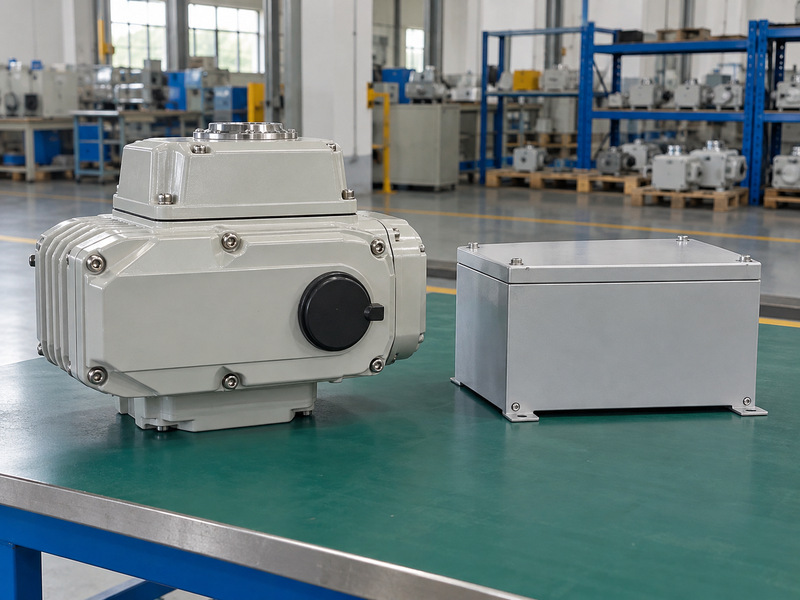
Power loss produces only the response supported by the selected assembly. An electric triple eccentric butterfly valve does not automatically close because it has an electric motor. Specify the required position, movement time, energy source, and behaviour on power restoration, then require evidence for that configuration.
Separate each loss scenario
Distinguish loss of motor power, control power, command signal, and communications. These events can have different outcomes. If a stored-energy or backup-powered arrangement is proposed, review its available energy, monitoring, maintenance, and ability to complete the specified movement under the defined valve load. Specify how a depleted or unavailable backup source appears to the plant operator before a demand occurs.
A safety-related application needs its own system requirements and applicable evidence. A fail-close description or an actuator certificate alone cannot establish the complete safety function. Include the valve, drive, control arrangement, diagnostics, and required testing in the responsible system engineer's review.
- Define each loss event and desired response.
- Confirm how operating energy remains available.
- Test restoration and restart behaviour.
| Event | Required written response |
|---|---|
| Motor-power loss | Defined movement or retained condition |
| Signal loss | Configured control response |
| Power restoration | Permitted restart sequence |
9. What environmental evidence should you request?
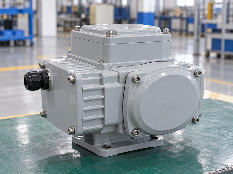
Request environmental evidence for the exact actuator and installed accessories. An electric triple eccentric butterfly valve may face rain, washdown, corrosive air, heat, or a classified hazardous area. Each condition needs its own selection check; enclosure ingress protection does not establish explosion protection.
Check the installation conditions
Confirm ambient limits, coating specification, cable entries, glands, earthing, and condensation provisions. Review heat transferred from the process and any required separation or shielding. Transport plugs and unfinished cable entries may not provide the protection needed after installation. Check storage arrangements too, especially if the assembly will wait outdoors before installation and energisation.
For a hazardous area, match the actual equipment marking and certificate conditions with the project's classification. Include accessory enclosures and entries in that review. For a less demanding water application, compare the documented wafer butterfly valve options against the duty before specifying a different construction.
- State ambient, exposure, and area classification.
- Verify evidence for the supplied configuration.
- Review entries and accessories after installation.
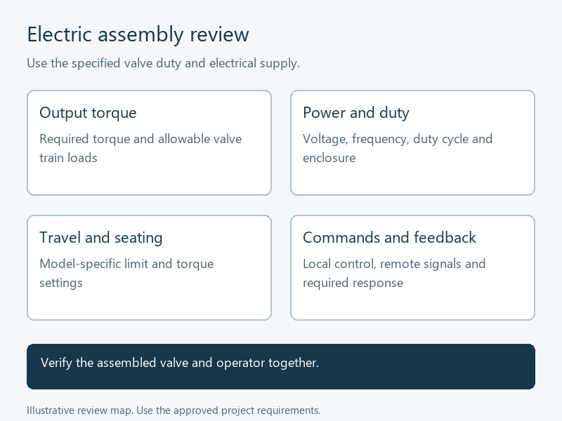
| Exposure | Evidence to review |
|---|---|
| Water and dust | Selected enclosure protection |
| Temperature and corrosion | Applicable limits and finish |
| Hazardous atmosphere | Marking, certificate, and conditions |
10. How should FAT and site commissioning be recorded?
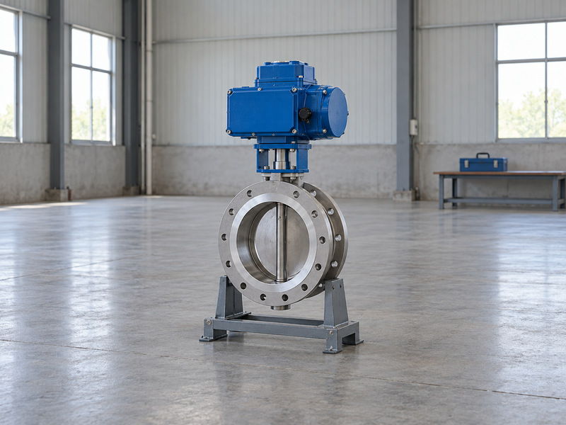
Record tests against the complete approved assembly and repeat installation-dependent checks at site. An electric triple eccentric butterfly valve factory acceptance test should connect the valve identity, actuator configuration, settings, and observed function. A bare-valve pressure report leaves the drive and control sequence unverified. Identify hold points and witness requirements early so the supplier can include them in the production schedule.
Build the handover record
Agree the factory test scope before manufacture. Include direction, full travel, seating action, commands, feedback, alarms, and specified failure responses. Record the test supply and any closure-test conditions under the specified product standard and, where required, ISO 5208. At site, check delivered configuration, installation clearance, wiring, earthing, supply, and the authorised operating sequence.
- Retain approved drawings and final settings.
- Resolve deviations before operational handover.
- Give maintenance staff the correct instructions.
| Record | Required connection |
|---|---|
| Factory acceptance | Actual assembly and test conditions |
| Site commissioning | Installed power, controls, and function |
| Handover | Final revisions and approved settings |
RUITO's manufacturing and project documentation information provides background for an enquiry. Request confirmation of the specific triple-offset supply scope, operating assembly, and available qualifications. Contact us with the duty, supply conditions, signal schedule, and acceptance requirements for a configuration-specific availability review.
Questions buyers ask about electric actuation
Q1. Can the actuator be selected from valve size alone?
No. Size does not define operating torque. Supply the service, differential, direction, temperature, cycling duty, and valve torque requirements.
Q2. Does a closed indication prove tight shutoff?
No. It reports a configured position or switching condition. Verify seating setup and the specified leakage test separately.
Q3. Will a standard electric actuator close without power?
Do not assume it will. Movement requires a selected arrangement with sufficient operating energy and a defined failure response.
Q4. Can I copy torque settings from a similar valve?
Use the approved instructions for the actual assembly. Similar body size or actuator appearance cannot establish identical settings.
Q5. Can factory testing replace site commissioning?
No. Site installation introduces wiring, supply, control, alignment, and access conditions that require their own checks before service.