
Select a pneumatic triple eccentric butterfly valve from the valve load, air conditions at the actuator, and required failure response. Header pressure and actuator catalogue torque leave several questions unanswered. Ask the supplier to match the valve, drive, air circuit, coupling, accessories, and test plan as one assembly, with assumptions recorded before purchase.
1. What defines a pneumatic triple eccentric butterfly valve?
A pneumatic triple eccentric butterfly valve combines a triple-offset valve with an air-powered operating assembly. Valve geometry defines how its sealing arrangement moves; the actuator and air circuit determine how operating energy reaches the shaft. Confirm the selected construction, service limits, and complete automation scope before comparing quotations.
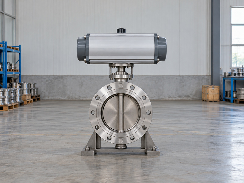
Start with the process duty
State the fluid, temperature, working pressure, closing differential, and required pressure direction. Specify the leakage acceptance criterion and whether the valve provides isolation or regulation. A pneumatic actuator can operate different valve designs, but adding one cannot qualify an unsuitable valve for the process.
List the actuator, bracket, coupling, solenoid, filter-regulator, positioner, switches, and tubing included in the purchase. Mark customer-supplied items explicitly. Otherwise, two quotations may appear comparable while leaving different parts of the operating circuit for the installation contractor to resolve. Ask one responsible supplier to reconcile the valve and actuator instructions for the final assembled configuration.
- Define the process and acceptance requirements.
- Identify every supplied air and mechanical component.
- Assign responsibility for assembled operation.
| Selection layer | Information needed |
|---|---|
| Valve | Service and shutoff requirements |
| Actuator | Output, travel, and operating arrangement |
| Air circuit | Supply, accessories, and failure response |
2. What minimum air pressure reaches the actuator?
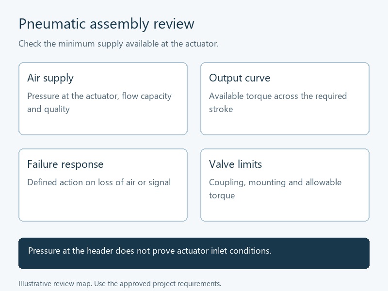
Use the minimum available pressure at the actuator under the defined operating demand. A pneumatic triple eccentric butterfly valve can receive less pressure during movement than the plant header gauge suggests. Regulators, tubing, fittings, filters, and shared users affect the air delivered at the point of use.
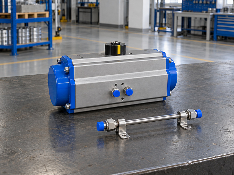
Separate static and operating pressure
Ask the plant engineer to identify the minimum point-of-use supply and the conditions that produce it. Include simultaneous valve operation, compressor or receiver limitations, and regulator performance. A reading taken with no air flowing does not describe the supply throughout a commanded stroke. Retain the stated demand case with the pressure record so later equipment additions can be reviewed against it.
Give the supplier both minimum and maximum pressure conditions. Minimum pressure affects available air-driven torque; maximum pressure affects component limits and potential output loads. Specify the measurement point so the actuator supplier and air-system designer use the same basis for selection and acceptance.
- Locate the pressure measurement point.
- Include simultaneous operating demand.
- Confirm minimum and maximum supply cases.
| Pressure value | What it describes |
|---|---|
| Header pressure | Upstream distribution condition |
| Static local pressure | Point-of-use condition without demand |
| Minimum operating supply | Selection basis under stated demand |
3. How should torque be checked across the stroke?
Compare the valve's required torque with the actuator's available torque at relevant points through opening and closing. A pneumatic triple eccentric butterfly valve needs adequate unseating, running, and seating output under the specified conditions. Checking one advertised peak value can leave part of the stroke unsupported.
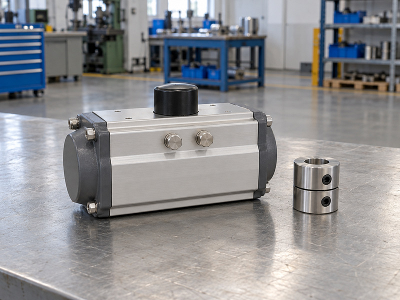
Compare the actual torque curves
Obtain the valve torque basis for differential pressure, direction, temperature, packing, and service condition. Request actuator output data for the selected mechanism and minimum supply. For spring-return operation, review air-stroke and spring-stroke output separately, including available output at the end of the required failure movement. Keep the selected spring arrangement identifiable so a later replacement actuator preserves the accepted output characteristics.
Agree the sizing margin rather than inventing a universal multiplier. Then check maximum possible output against the allowable shaft, coupling, bracket, and drive loads. An actuator with more output may still be unsuitable if it can overload a component or fails to complete the spring stroke.
- Compare output through both operating directions.
- Check air and spring curves where applicable.
- Record sizing margin and allowable loads.
| Review item | Required comparison |
|---|---|
| Required torque | Actual valve and duty |
| Available torque | Selected actuator and supply |
| Allowable torque | Components in the drive path |
4. Which actuator arrangement gives the required fail action?
Select the actuator and circuit together for the specified loss event and required valve response. A pneumatic triple eccentric butterfly valve can use spring-return or double-acting operation. Those descriptions identify operating arrangements; they do not, by themselves, prove the installed valve will reach the required position after every fault.
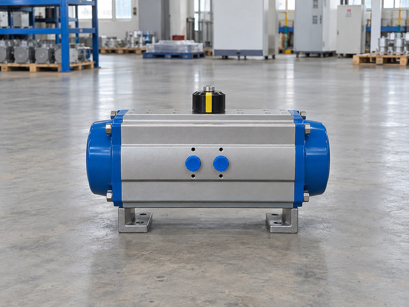
Define what has failed
Distinguish loss of instrument air, solenoid power, control signal, and positioner communication. Spring-return operation depends on correct assembly direction, sufficient spring output, and an air path that permits the opposing chamber to vent. Double-acting operation needs pressure for powered movement in either direction and does not guarantee fail-close on air loss.
Where a safety function is specified, request the applicable assessment and instructions for the complete application. Spring return alone cannot establish safety-system suitability. Any stored-air solution also needs defined capacity, monitoring, leakage assumptions, and maintenance arrangements under the responsible system design. Include the manual override's required operating state and any controls against leaving the automatic function inhibited.
- Name each fault and desired position.
- Verify venting and available failure-stroke torque.
- Test the assembled failure response.
| Arrangement | Check before acceptance |
|---|---|
| Spring return | Direction, torque, and exhaust path |
| Double acting | Defined response on loss of air |
| Stored-air support | Capacity and control assumptions |
5. What air quality does the complete assembly require?
Specify air quality for the actuator and every pneumatic accessory at the point of use. A pneumatic triple eccentric butterfly valve assembly may include a positioner or solenoid with requirements that differ from the actuator's. Use the strictest applicable component requirements when defining the supply arrangement.
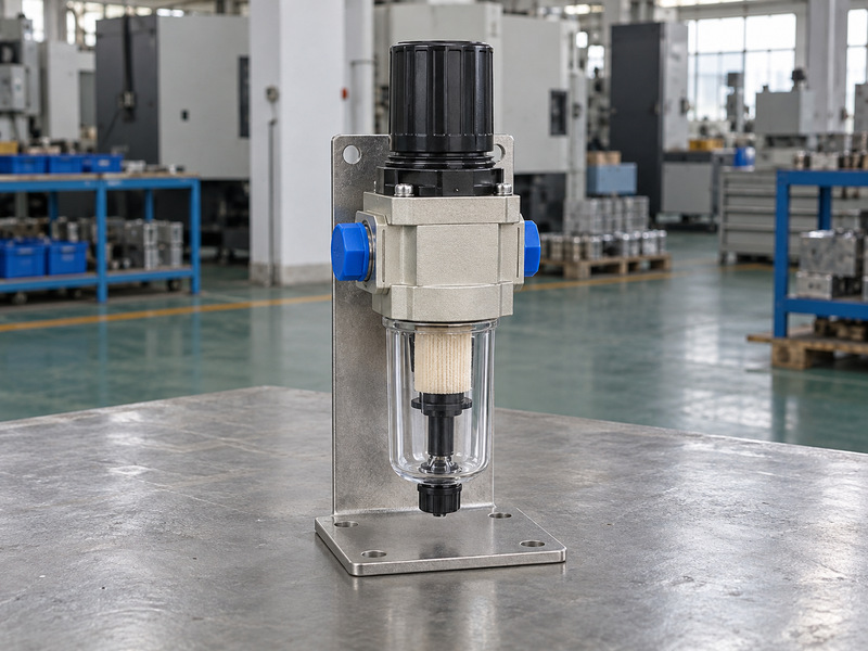
Match treatment with the environment
Request the permitted particle, moisture, and oil conditions from the selected manufacturers. ISO 8573-1 defines compressed-air purity classes for particles, water, and oil; it does not assign one universal class to every valve assembly. Record the required classes and measurement location in the specification.
Review the lowest expected temperature against the specified moisture condition and drying provision. Arrange drains and filter access so maintenance staff can service them. Do not add an oil-mist lubricator by habit; confirm compatibility with the selected actuator and sensitive control accessories. Specify who maintains local treatment equipment when the valve package and air system have different owners.
- Obtain air-quality requirements for each component.
- Check drying for the actual ambient conditions.
- Provide accessible filtration and drainage.
| Air condition | Assembly question |
|---|---|
| Particles | What filtration does each component need? |
| Moisture | Is drying suitable for local temperature? |
| Oil | Is the specified supply compatible? |
6. How do tubing and accessories affect flow capacity?
Size the entire air path for the required operating response. A pneumatic triple eccentric butterfly valve can move slowly or inconsistently despite adequate static pressure when restrictions limit filling or exhaust. Review supply and exhaust capacity together rather than selecting tubing from connection-thread size alone.
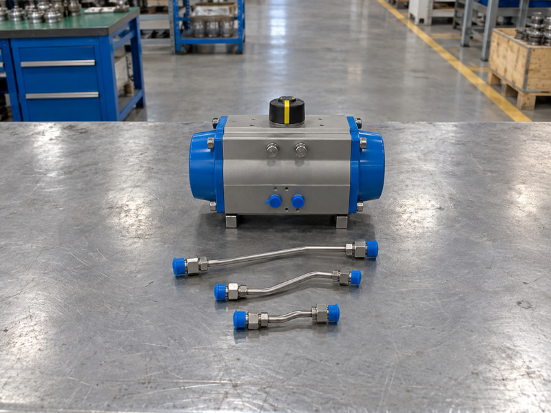
Follow air through the whole circuit
Check line length, internal diameter, fittings, filter-regulator capacity, solenoid flow, and any positioner or booster. Include exhaust silencers, speed controls, and quick-exhaust devices where fitted. Each component must suit the selected circuit and operating environment; adding a larger upstream line cannot remove every downstream restriction.
Request air-consumption data for the actual actuator, pressure basis, and cycle definition. Separate the air required for one operating sequence from continuous accessory demand. Use those data with simultaneous operations to review receiver and distribution capacity, without borrowing consumption figures from a different actuator size. Keep standard-volume and actual-volume reporting bases explicit when comparing consumption figures from different data sheets.
- Review supply and exhaust restrictions.
- Use configuration-specific consumption data.
- Include simultaneous strokes and accessory demand.
| Circuit element | Capacity check |
|---|---|
| Tubing and fittings | Length, bore, and restrictions |
| Control accessories | Required flow and pressure behaviour |
| Exhaust path | Venting capacity and environmental condition |
7. Which control accessories and feedback belong in the scope?
Choose accessories from the required command sequence, feedback, and fault response. A pneumatic triple eccentric butterfly valve used for on-off isolation may need a different circuit from one used for positioning. A positioner adds controlled positioning, but it cannot establish that the valve itself suits the proposed regulating duty.
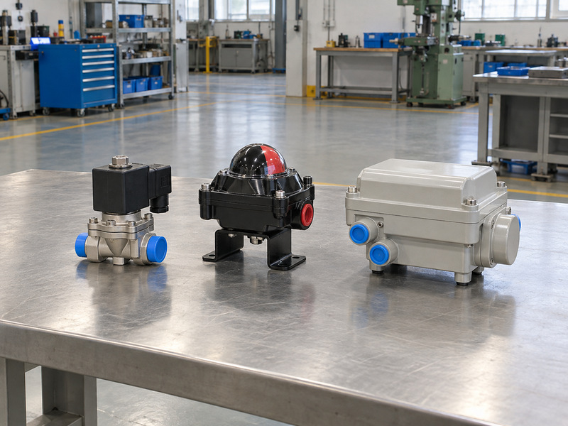
Write the accessory schedule
Specify solenoid voltage, circuit function, de-energised state, and required manual-override behaviour. Define switch contacts, position feedback, and any low-air alarm. Include environmental or hazardous-area evidence for electrical accessories where the project requires it, with the actual supplied markings and certificate conditions. Agree spare identification for each accessory so maintenance cannot substitute a visually similar but functionally different item.
RUITO's documented lug butterfly valve configurations provide a separate comparison for connection and service requirements. That product information does not confirm a triple-offset range. Keep both valve construction and automation scope explicit when asking whether a different assembly can be supplied.
- Map commands and de-energised states.
- Identify what each feedback device measures.
- Confirm accessory supply and approval scope.
| Accessory | Detail to define |
|---|---|
| Solenoid | Voltage, circuit, and default state |
| Positioner | Input, supply, and loss response |
| Switch or transmitter | Source and meaning of feedback |
8. How should coupling, limits, and seating be coordinated?
Coordinate the shaft connection and end positions with the valve manufacturer's seating requirements. A pneumatic triple eccentric butterfly valve needs correct engagement, alignment, and usable travel before accessory indication is calibrated. A pointer at closed does not prove that the disc has reached its required seating condition.
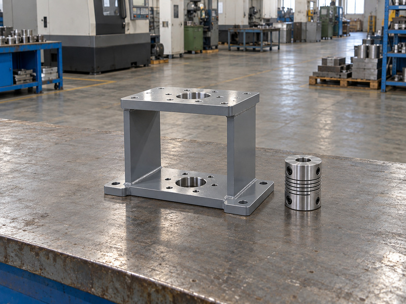
Use the approved assembly procedure
Check shaft projection, drive shape, coupling engagement, bracket stiffness, fasteners, and mounting orientation against the approved drawing. Confirm that the coupling neither bottoms out nor introduces unwanted shaft load. Provide support for the installed assembly and space to remove accessories without disturbing neighbouring pipework. Retain the interface drawing if the project plans to stock replacement actuators separately from the valves.
Set travel stops and feedback using the specific valve and actuator instructions. Avoid universal stop-bolt turns or angle adjustments. If leakage remains, investigate alignment, obstruction, travel, and available seating torque before changing the setup. Any authorised adjustment should be followed by the specified functional and closure checks.
- Confirm interface dimensions and allowable loads.
- Coordinate stops with the seating method.
- Verify feedback after mechanical setup.
| Assembly feature | Acceptance check |
|---|---|
| Coupling | Correct fit and engagement |
| Travel limits | Approved valve operating positions |
| Closed indication | Correctly calibrated signal condition |
9. How fast should the valve open and close?
Set stroke speed from the process requirement and system response. A pneumatic triple eccentric butterfly valve should complete its movement within the agreed operating window under defined supply and load conditions. The fastest unloaded workshop stroke may be unsuitable for a liquid system or fail to represent installed performance.
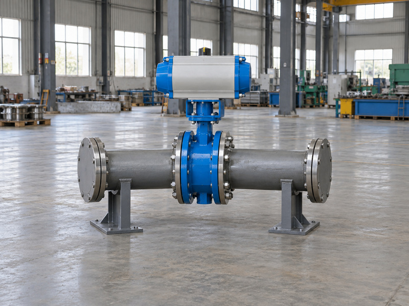
Review normal and failure movements
Ask the responsible system engineer to review closure time where pressure transients may occur. Define opening and closing times separately if the process needs them. Include the required failure stroke, because a spring-driven movement can behave differently from the normal air-driven movement. Identify where timing starts and ends so the factory result and the control-system response use the same definition.
Agree the speed-control arrangement with the actuator supplier and check its effect on venting and failure response. Record timing under stated test conditions, including supply and configuration. A timer result without that basis cannot establish the response under every operating load or air-supply condition.
- Specify acceptable timing for each movement.
- Review pressure-transient consequences.
- Verify speed controls in all required modes.
| Movement | Timing basis |
|---|---|
| Normal opening | Process requirement and available air |
| Normal closing | Isolation need and system transients |
| Failure stroke | Defined fault, load, and circuit state |
10. What should complete-assembly FAT and commissioning cover?
Test the approved operating assembly and retain records that identify its configuration. A pneumatic triple eccentric butterfly valve factory acceptance test should verify more than bare-valve pressure performance. The actuator, air circuit, controls, feedback, and specified failure actions need their own agreed checks before shipment. Identify witness points and any permitted simulations in the test procedure before arranging factory attendance.
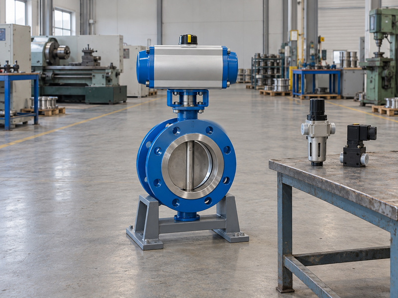
Connect factory and site evidence
Record identities, drawing revisions, settings, air conditions, direction, full travel, stroke times, and observed feedback. Include specified loss-of-air, loss-of-power, and signal-loss tests. Where closure performance is tested, retain differential, direction, medium, and leakage acceptance details with the assembly record.
- Reconcile delivered items with the approved scope.
- Close deviations before operational handover.
- Retain instructions and final setting records.
| Record | Required evidence |
|---|---|
| Factory acceptance | Complete configuration and conditions |
| Site commissioning | Installed supply and actual control sequence |
| Handover | Approved revisions and maintenance information |
At site, verify installation, point-of-use supply, air quality, tubing, electrical accessories, and control logic before commissioning. RUITO's manufacturing and documentation information supports an enquiry, while specific triple-offset availability and any special qualifications require written confirmation for the proposed order. Contact us with the process data, minimum air supply, failure-response schedule, and acceptance requirements for a configuration-specific supply review.
Questions buyers ask about pneumatic actuation
Q1. Can I size the actuator using header pressure?
Use the specified minimum supply at the actuator under the operating demand. Header pressure can differ from that condition.
Q2. Does double-acting operation guarantee fail-close?
No. Define and verify the air circuit's response to each loss event. Double-acting operation alone does not supply closing energy after air loss.
Q3. Is spring return enough for a safety application?
No. Review the complete safety function, selected configuration, available torque, applicable evidence, and testing requirements with the responsible system engineer.
Q4. Can faster closing solve a slow isolation response?
Check the cause and the system's permitted closing time. Air restrictions, supply limitations, or load can affect response, while faster closure may create pressure transients.
Q5. Does the closed switch confirm the leakage result?
No. It indicates a configured switching condition. Seating setup and leakage acceptance require separate verification under stated test conditions.