
Check triple offset butterfly valve dimensions against an approved general arrangement drawing and a recorded site survey. A replacement valve can share a nominal size with the old unit and still fail to fit. The review should cover the pipe connections, moving disc, drive interface, and space needed to install and maintain the complete assembly.
1. Which triple offset butterfly valve dimensions control fit?
Fit depends on the body interfaces, moving envelope, operator assembly, and maintenance clearances. Triple offset butterfly valve dimensions must describe the selected size, pressure class, connection, and actuator arrangement together. Matching one catalogue dimension leaves the other interfaces open.
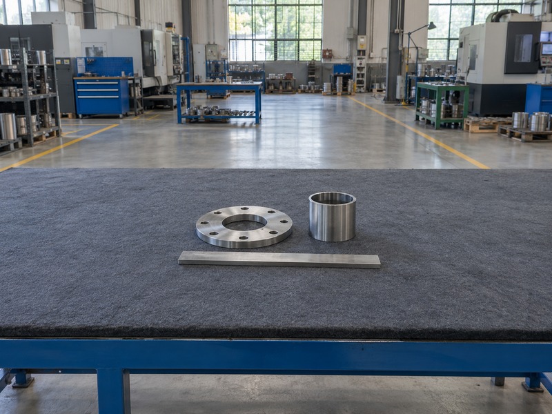
Divide the review into interfaces
Start at the pipeline and work outward. Check face-to-face length and flange details, then the adjacent bore and disc sweep. Continue through the shaft connection, mounting bracket, gearbox or actuator, and the surrounding structures. Give each group a drawing reference and identify which interfaces are fixed by the existing installation.
Keep physical fit separate from service suitability. An assembly can fit the available space while carrying unsuitable pressure, temperature, material, or leakage requirements. Both reviews must close before purchase, but a dimensional worksheet should show exactly which physical interfaces have been checked.
- Compare complete assemblies in their intended installed orientation.
- Assign a reference to each interface dimension.
- List unresolved measurements as open items rather than assumed matches.
| Interface group | Dimensions to review |
|---|---|
| Pipeline | Length, flange pattern, and adjacent bore |
| Drive | Shaft, mounting flange, and coupling |
| Surroundings | Operating, removal, and handling space |
2. How should you read the GA drawing before measuring?
Read the title block, revision, units, views, notes, and configuration details before using any dimension. Triple offset butterfly valve dimensions are useful only when the drawing matches the proposed assembly. An outline for a bare valve cannot establish the envelope of a later actuator package.

Establish the drawing basis
Identify the pipe centerline, shaft centerline, mounting plane, and sealing-face references. Check whether each view shows the disc open or closed and whether the actuator can be supplied in more than one orientation. Read dimension symbols through the drawing legend; letters such as H or L do not have universal meanings across manufacturers.
Use stated dimensions and tolerances rather than scaling a printed drawing. Perspective illustrations and reduced PDF prints can distort apparent distances. If a required interface is undimensioned, request an updated drawing or supplementary detail and link that answer to the same revision under review. Check whether general drawing tolerances apply or a specific dimension carries its own limit.
- Confirm drawing number, revision, units, and assembly identity.
- Match the views with the intended installation orientation.
- Request missing dimensions instead of estimating them from the picture.
| Drawing check | Evidence to retain |
|---|---|
| Configuration | Size, class, connection, and operator |
| References | Datums, centerlines, and view orientation |
| Control | Revision, approval status, and tolerances |
3. What do DN and NPS leave unspecified?
DN and NPS identify nominal size and do not state every actual internal or external measurement. Triple offset butterfly valve dimensions therefore need more detail than the size designation. Nominal size alone cannot establish the valve's clear bore, flange geometry, or disc clearance.
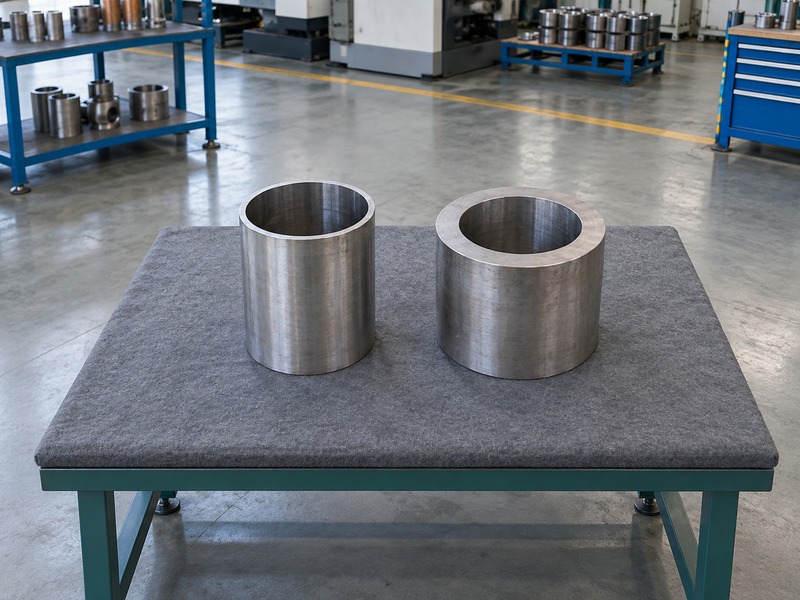
Record the actual adjacent bore
Request the valve passage and disc-envelope information needed for the installation. Record the mating pipe's actual internal diameter or its controlled pipe specification, including wall thickness where relevant. Nearby reducers, linings, weld intrusions, and adapters can reduce the available opening even when the nominal sizes match. Mark which side of the valve each bore measurement describes so the comparison preserves its location.
Keep size designations separate from unit conversion. Converting a measured inch dimension into millimetres preserves that measurement; it does not turn an NPS designation into a measured bore. If the project uses mixed units, retain the source value and identify which unit controls manufacturing and acceptance.
- Record nominal size and actual interface measurements separately.
- Include pipe wall, lining, and nearby restrictions in the bore review.
- Preserve the controlling unit when transcribing dimensions.
| Item | What it establishes |
|---|---|
| DN or NPS | Nominal size designation |
| Actual internal diameter | Available opening at a stated location |
| Pipe specification | Basis for the mating pipe geometry |
4. How do face-to-face and gasket datums affect fit?
Face-to-face length establishes the valve body's axial installation interface between specified reference faces. Triple offset butterfly valve dimensions must identify those datums and the applicable dimensional pattern. Two valves with the same nominal size and class can still require different installed lengths.
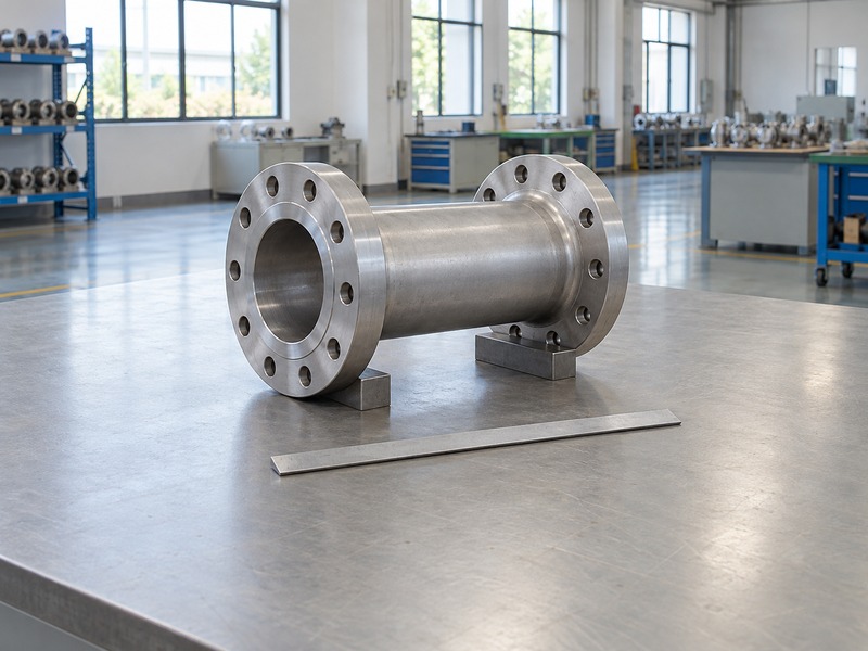
Compare the same reference faces
The official scope of ASME B16.10 connects installation interchangeability with material, valve type, size, rating class, and end connection. Use the contract edition and applicable pattern together with the approved drawing. A standard designation without the relevant pattern cannot resolve a length discrepancy.
Identify whether the dimension ends at sealing faces, body faces, or another stated reference. Add the specified compressed gasket stack to a layout calculation only where those gaskets lie outside the stated datums. RUITO's flanged butterfly valve arrangements provide connection context; obtain the selected assembly's own length and facing details. Record any dismantling-joint adjustment separately rather than hiding it inside the valve dimension.
- Compare existing and proposed lengths from equivalent datums.
- Record facing type and the gasket basis used in the layout.
- Include applicable tolerances when checking the available pipe gap.
| Length check | Record |
|---|---|
| Valve dimension | Value, datums, and pattern |
| Gasket stack | Specified compressed thickness basis |
| Site gap | Measured references and available adjustment |
5. Which flange details must match the pipeline?
The flange standard, size, class or PN designation, facing, and bolt arrangement must suit the mating connection. Triple offset butterfly valve dimensions should include enough flange detail to verify that match. A shared hole count or similar outside diameter cannot establish compatibility.
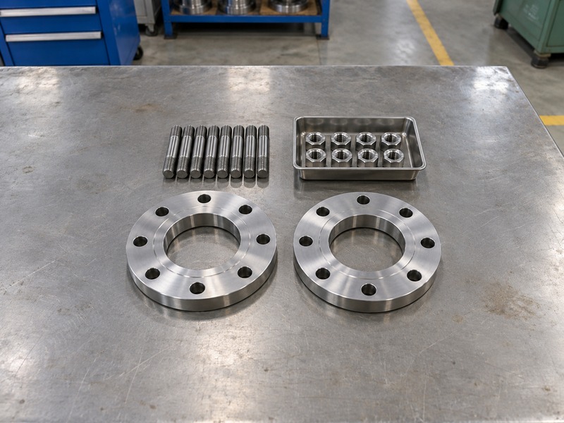
Check the complete bolt arrangement
Compare bolt-circle diameter, hole count, hole diameter or thread, and hole orientation relative to the shaft. Check flange thickness, access for nuts and tools, and any threaded-hole engagement requirements. Confirm bolt length against the complete joint stack rather than copying the old fastener length. Identify blind or obstructed holes that prevent a through-bolt arrangement shown in a generic installation sketch.
Connection style changes the review. A wafer butterfly valve sits between mating flanges, while a double-flanged assembly has its own end flanges. Keep each style's dimensions and bolting arrangement with its own drawing; neither serves as a dimensional template for every triple-offset valve.
- Identify the exact flange standard and facing on both sides.
- Compare all hole-pattern details, including orientation.
- Review the proposed gasket and fastener arrangement as a complete joint.
| Flange feature | Comparison needed |
|---|---|
| Sealing interface | Facing geometry and gasket compatibility |
| Hole pattern | Circle, quantity, size, and orientation |
| Joint stack | Flange thickness, bolts, and tool access |
6. How do you check the open-disc envelope?
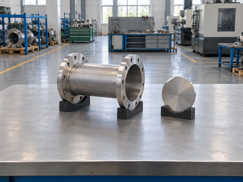
Check the disc's swept volume against every nearby internal restriction through the required travel. Triple offset butterfly valve dimensions should show the clearance information needed on both sides of the body. The closed-disc outline cannot establish that the valve will open after installation.
Review both sides of the connection
Ask how far the disc projects beyond each relevant face and which adjacent bore restrictions the manufacturer permits. Compare that envelope with the actual pipe, reducer, lining, gasket bore, and nearby equipment. A check valve, strainer, or closely mounted fitting can create an obstruction outside a simple pipe-bore comparison.
Use a sectional detail or controlled model when the arrangement is crowded. Include alignment and specified tolerances in the review rather than accepting a drawing where surfaces only appear to clear. Any physical travel check must follow the approved installation procedure with the assembly safely isolated and supported. Obtain a written clearance decision where an adapter or adjacent fitting changes the manufacturer's assumed arrangement.
- Obtain the required disc-envelope and adjacent-bore information.
- Include gasket intrusion and nearby equipment in the check.
- Resolve interference before fitting the actuator or applying operating force.
| Clearance location | Compare with the disc envelope |
|---|---|
| Valve connections | Mating bore and gasket opening |
| Adjacent pipework | Lining, reducers, and weld restrictions |
| Nearby equipment | Internal parts and required separation |
7. What dimensions connect the shaft and actuator?
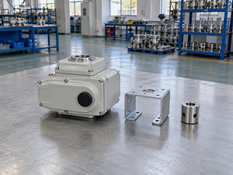
The mounting flange, shaft end, coupling, and bracket establish the physical drive interface. Triple offset butterfly valve dimensions must describe these parts as one assembly. A matching mounting-flange designation does not establish a compatible shaft connection or suitable actuator output.
Trace the complete mechanical connection
Record mounting-hole details, pilot or locating features, shaft shape, key or spline information, and engagement length. Check bracket height and coupling position against the actual shaft projection. Include the reference orientation of the closed valve so the installed drive and position indication agree. Confirm whether dimensions describe the bare shaft or a supplied adapter before comparing the mating parts.
Review torque and allowable loads alongside the dimensions. A coupling can fit physically while lacking adequate capacity, and an oversized operator can overload another part of the drive path. Confirm the specified travel, settings, and assembly orientation rather than approving the package from a hole-pattern match.
- Obtain interface drawings for the valve and selected operator.
- Check engagement, locating features, and closed-position references.
- Confirm capacity and settings separately from the dimensional match.
| Interface | Details to verify |
|---|---|
| Mounting flange | Holes, locating features, and orientation |
| Shaft and coupling | Shape, dimensions, and engagement |
| Bracket assembly | Height, alignment, and load capacity |
8. How much operating and removal space is needed?
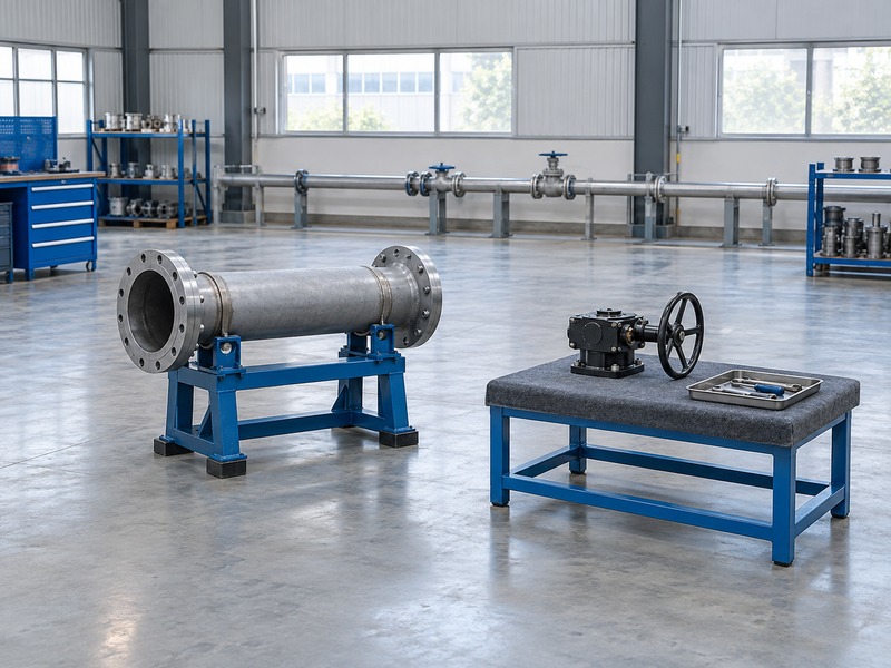
Space must cover operation, inspection, component removal, and handling of the selected assembly. Triple offset butterfly valve dimensions often show an overall envelope, but maintenance can require more room. Ask for the additional access limits before approving a crowded installation.
Draw the maintenance route
Check handwheel sweep, manual override access, actuator cover removal, cable entries, and access to packing or retainer fasteners. Confirm the direction and distance required to withdraw the actuator, coupling, or other planned replacement parts. Include bolt removal and the valve extraction path in the outage layout.
Record assembly mass and lifting requirements separately from geometric clearance. A valve may pass through an opening yet remain inaccessible to the required lifting equipment. Keep supports, platforms, insulation, and neighbouring equipment in the drawing review; each can occupy space that looks clear on a valve-only outline. Check the planned temporary support position during removal, when the normal installed support may be unavailable.
- Obtain operating and maintenance envelopes for the complete package.
- Check tool, bolt, component, and valve removal routes.
- Review lifting access with the documented mass and approved handling method.
| Space category | Check |
|---|---|
| Operation | Handwheel, override, and local controls |
| Maintenance | Covers, fasteners, and component withdrawal |
| Replacement | Extraction path, lifting access, and supports |
9. How should a site measurement record be prepared?
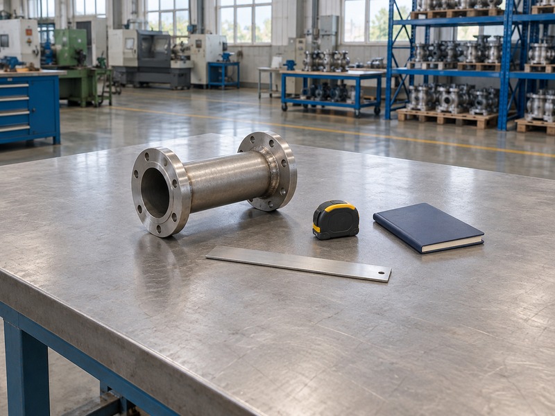
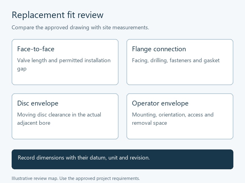
Prepare a dated record that identifies every measurement's location, datum, unit, and uncertainty. Triple offset butterfly valve dimensions should be compared with traceable site information. A number without its measurement basis can create a false match between the existing installation and proposed valve.
Separate observation from inference
Record which values were measured, read from an existing drawing, or inferred from identification marks. Photograph the reference points and nearby restrictions where permitted. If insulation, access, or operating conditions prevent a reliable measurement, mark that field unresolved and specify how it will be verified.
Use suitable measuring equipment and record the precision the method supports. Keep both flange alignment and the axial gap in the survey. An old installation may contain distorted pipework or unrecorded modifications, so copying its apparent dimensions does not establish an acceptable replacement layout. Retain the survey date because later pipework or platform work can invalidate an earlier clearance record.
- Identify the valve location and survey conditions.
- Preserve source values and controlling units without silent rounding.
- Assign an owner and verification step to each unresolved field.
| Record field | Required detail |
|---|---|
| Measurement | Value, unit, datum, and method |
| Evidence | Drawing reference or location photograph |
| Open item | Access limit and verification action |
10. What belongs in a replacement-fit worksheet?
A replacement worksheet should compare existing conditions, proposed dimensions, and acceptance status interface by interface. Triple offset butterfly valve dimensions need a documented source and revision for each proposed value. Keep discrepancies visible until an approved solution closes them.
Request a complete configuration review
Include dimensional differences, required pipework changes, actuator orientation, and maintenance access. Use RUITO's manufacturing and inspection information to frame the enquiry, then request confirmation of the proposed supply configuration and its supporting drawings. Obtain the selected drawing before using a catalogue dimension for site work. Keep the approved worksheet with the purchase file and recheck affected interfaces after any assembly revision.
- Give each interface a source, comparison, and status.
- Identify modifications and their responsible reviewer.
- Approve the final assembly drawing before committing the layout.
| Worksheet group | Compare and close |
|---|---|
| Pipeline fit | Length, flanges, bore, and disc clearance |
| Operator fit | Shaft, coupling, bracket, and orientation |
| Installation access | Operation, removal, lifting, and supports |
Contact us with the existing drawing, site measurements, and service requirements to confirm the proposed configuration, dimensional fit, and available evidence.
Questions buyers ask about dimensional fit
Q1. Does the same DN guarantee the same face-to-face length?
No. Confirm the valve type, connection, dimensional pattern, and approved drawing for each assembly.
Q2. Can a catalogue picture provide a missing dimension?
Request a dimensioned drawing. Scaling a picture cannot establish the interface or its tolerance.
Q3. Should gasket thickness be added to face-to-face length?
Use the drawing datums. Include the specified compressed gasket stack only where it lies outside those references.
Q4. Does a matching actuator flange prove the package fits?
No. Check shaft geometry, coupling engagement, bracket arrangement, orientation, torque capacity, and access.
Q5. What if a critical site dimension cannot be measured?
Keep it unresolved and arrange a controlled verification. Identify who will confirm the value before layout approval.