
Choose a gear actuator by comparing its output motion, torque-speed curve, duty and temperature limits under the same operating conditions. A larger motor or a different gear material cannot resolve every mismatch. Define what the driven valve or mechanism must do, then check how the complete actuator delivers that motion.
Images are AI-generated illustrations of generic equipment configurations.
1. What does a gear actuator change?
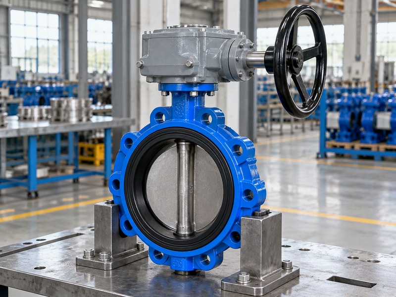
A gear actuator changes the motor’s or operator’s input motion through a gear train before driving the load. Reduction can increase available torque while reducing output speed. For a valve application, you also need the correct output travel and a mounting arrangement that transfers the load without distorting the shaft connection.
What should you define before comparing products?
Specify whether the load needs rotary or linear movement, its required travel and its resistance throughout that movement. A butterfly valve requires part-turn rotation at its stem, while a linear mechanism needs a different final drive. Then identify the power source, operating frequency and required position after loss of power. These requirements describe the actuator’s job more accurately than a request for a particular motor size or a housing that resembles the existing unit.
- Identify rotary or linear output motion.
- State travel, load and operating frequency.
- Describe the available power and control signals.
Key takeaway: Write the output requirement before selecting the internal gearing or power source.
| Check | What to confirm |
|---|---|
| Input side | Power source, speed and permitted duty. |
| Output side | Motion, travel and required load capacity. |
2. How does ratio change speed and torque?
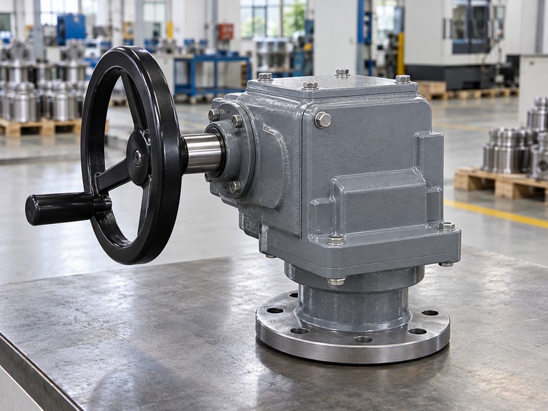
A gear actuator ratio links input speed to output speed, while efficiency affects the usable torque. In a simple reduction, output speed equals input speed divided by the ratio. Check the complete actuator’s performance because motor behavior, additional stages and control settings can change the result under load.
What does a speed calculation tell you?
For an illustrative constant input speed of 30 rpm and an 80:1 reduction, the output speed is 0.375 rpm. A 90-degree output movement would take 40 seconds before allowing for acceleration, deceleration or control effects. That calculation helps compare proposed reductions, but it does not prove the motor can maintain that speed against the actual valve torque. Request loaded operating time as well as the nominal ratio and unloaded speed.
- Use the total reduction across supplied stages.
- Separate unloaded speed from loaded stroke time.
- Compare the required torque throughout travel.
Key takeaway: Use ratio calculations to check a proposal, then confirm the complete actuator’s loaded performance.
| Check | What to confirm |
|---|---|
| Illustrative output speed | 30 rpm ÷ 80 = 0.375 rpm. |
| Illustrative quarter turn | 0.25 revolution ÷ 0.375 rpm = 40 seconds. |
3. When do steel and polymer gears differ?
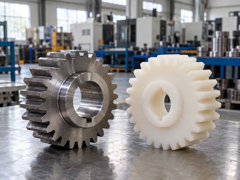
Steel and polymer gears in a gear actuator differ in properties, but material names alone do not establish performance. Gear geometry, load, temperature, lubrication and manufacturing quality also affect the result. Compare approved torque, life and environmental limits for the actual design rather than treating one material as a universal upgrade.
What should a materials comparison include?
A polymer gear can suit a design that controls its load and temperature, while a steel gear may need attention to noise, lubrication and mating surfaces. Neither choice excuses overloading or repeated operation against a mechanical obstruction. Ask for the material identification and the conditions behind any endurance or temperature claim. If a supplier proposes a change, review tooth geometry and the mating gear as well as the material, since changing one component can affect the pair.
- Compare ratings under the same load and temperature.
- Identify the mating gear and lubricant.
- Review evidence for material substitutions.
Key takeaway: Select a tested gear arrangement rather than approving a material change by name alone.
| Check | What to confirm |
|---|---|
| Material comparison | Temperature, loading, noise and compatibility. |
| Design comparison | Geometry, manufacture and demonstrated performance. |
4. What can you expect from worm gearing?
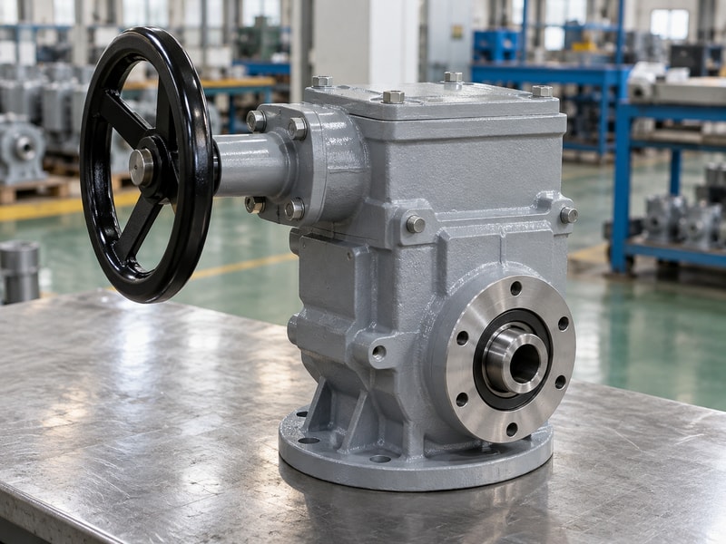
Worm gearing in a gear actuator can provide a large reduction between nonparallel, nonintersecting shafts in a compact package. Sliding contact introduces losses that must appear in the torque calculation. The design may resist back-driving under defined conditions, but the application still needs an explicit position-holding requirement.
Which advantages have a corresponding cost?
A high reduction can lower the required input effort and reduce output speed. It also increases the input travel needed for the same valve movement, and friction generates heat during operation. A mechanism suitable for occasional manual isolation may therefore need a different review when driven repeatedly by a motor. Check operating frequency, allowable input speed and thermal limits together before transferring a manual gearbox selection into an automatic valve package.
- Include efficiency in the torque calculation.
- Check turns or operating time across the stroke.
- Confirm powered-duty and holding limits.
Key takeaway: Assess reduction, heat and operating time together when considering a worm drive.
| Check | What to confirm |
|---|---|
| Mechanical benefit | Reduction changes effort and output speed. |
| Operating tradeoff | Input travel and losses require review. |
5. When does another gear arrangement fit?
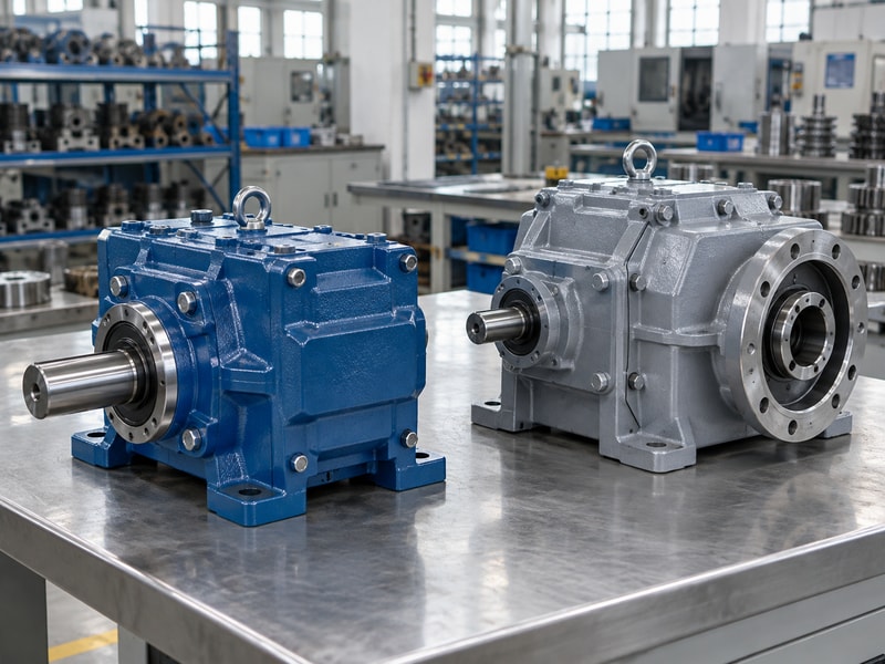
Another gear actuator arrangement may fit when shaft layout, efficiency, reduction or package size makes a worm drive unsuitable. Spur and planetary arrangements are examples of different ways to transmit and reduce motion. The final choice must still provide the output motion and control behavior required by the driven equipment.
How should you compare alternatives?
Start with the required output and available installation envelope, then compare complete-drive ratings on the same basis. A compact planetary stage, for example, does not eliminate the need for suitable bearings, output support or an adequate coupling. Nor does a higher advertised efficiency establish an acceptable holding function. Ask the supplier to show how each proposed arrangement meets the load, positioning, duty and access requirements rather than comparing isolated gear sets without their supporting components.
- Compare the complete drive envelope.
- Check shaft loads and output support.
- Keep position holding and control accuracy in the comparison.
Key takeaway: Compare arrangements by the job they perform within the assembly, not by a preferred gear label.
| Check | What to confirm |
|---|---|
| Mechanical fit | Shaft layout, reduction and supported loads. |
| Functional fit | Duty, positioning and holding behavior. |
6. How do duty and temperature affect a gear actuator?
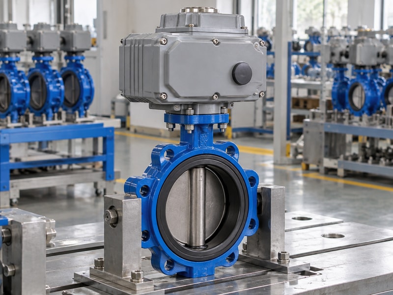
Duty and temperature affect a gear actuator through motor heating, lubricant behavior, material limits and the frequency of load reversals. A short intermittent rating does not permit continuous cycling. Specify ambient conditions and the real operating sequence, including starts, stops, recovery periods and any periods spent holding a load.
What does the duty statement need to describe?
A valve that moves a few times per week has a different operating pattern from one making frequent positioning corrections. Record the expected number of starts, complete strokes and small movements over a defined period. Include the warmest and coldest ambient conditions at the actuator itself, especially where insulation or adjacent equipment affects heat transfer. Ask the supplier to state any derating or recovery requirement that applies to the selected motor and gear train.
- Separate full strokes from frequent small corrections.
- State ambient extremes at the installed actuator.
- Confirm recovery periods and applicable derating.
Key takeaway: Give the supplier an operating sequence that can be checked against the actuator’s duty rating.
| Check | What to confirm |
|---|---|
| Intermittent isolation | Check starts, stroke load and recovery. |
| Positioning service | Check frequent reversals and thermal duty. |
7. Which mounting details need checking?
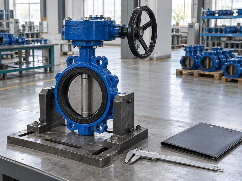
A gear actuator mounting interface must match the driven shaft, flange and supporting structure, with enough engagement to transmit the required torque. Similar bolt patterns can conceal different shaft forms or registers. Verify the complete connection, including any adapter that sits between a valve and the actuator output.
What should you inspect before assembly?
Check the output bore, stem projection, pilot fit, bolt thread and fastener engagement against the approved drawing. Confirm that a coupling can reach its intended engagement without bottoming before the faces meet. For an elevated bracket, review its stiffness and the support of the valve stem rather than using a longer coupling to bridge an unexplained gap. Assemble the parts without forcing them into alignment and check unobstructed travel before performing loaded tests.
- Compare actual shaft and bore geometry.
- Check register fit and coupling clearance.
- Review the stiffness of any mounting bracket.
Key takeaway: Treat adapters and brackets as loaded components that need dimensions and approval.
| Check | What to confirm |
|---|---|
| Geometric fit | Shaft, bore, register and fasteners. |
| Load transfer | Coupling engagement and bracket stiffness. |
8. What feedback does the application need?
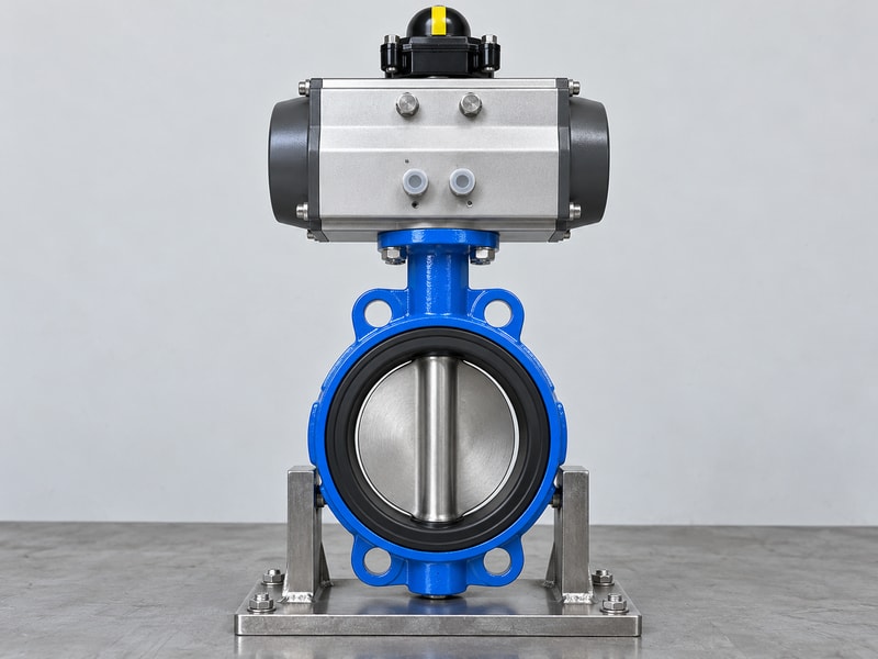
Feedback for a gear actuator should report the information the application needs, such as end position, continuous position or a detected fault. An electrical command does not prove that the driven valve moved. Choose sensing and control functions with attention to where position is measured relative to the gear train and coupling.
Why does sensor location matter?
A sensor on the motor side can indicate input movement even if a downstream connection has loosened. A sensor nearer the valve shaft observes a different point in the load path, although it still does not prove acceptable seat leakage. Backlash also becomes relevant when motion reverses during positioning. Define required accuracy, repeatability and end-position confirmation, then ask how the complete assembly will demonstrate those functions during acceptance.
- State required end-position or continuous feedback.
- Identify the measurement point on the assembly.
- Separate position confirmation from leakage acceptance.
Key takeaway: Specify what the feedback proves and where the measurement comes from.
| Check | What to confirm |
|---|---|
| Position signal | Describes motion at the sensing location. |
| Isolation performance | Needs the valve’s separate leakage test. |
9. Which tests compare gear actuator performance?
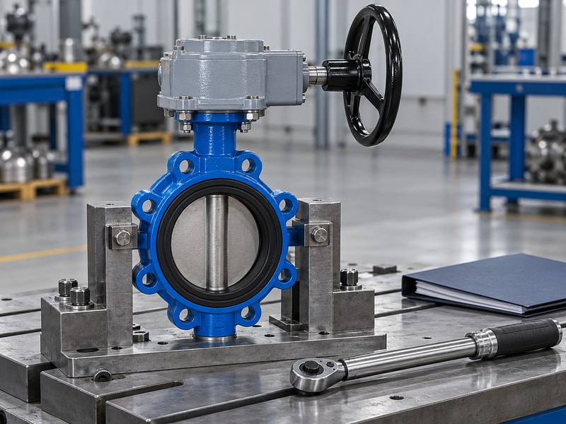
Compare gear actuator performance using the same load profile, supply condition, ambient temperature and acceptance method. Unloaded bench movement cannot establish loaded stroke time or sustained duty. Tests should cover the complete supplied package so that the mounting interface, coupling and controls are included in the result.
What should the test record contain?
Identify the assembly and drawing revision, then record the applied load conditions, supply, travel and measured operating time. Check direction, limits, feedback and any specified manual operation. For positioning duty, include reversals and the agreed accuracy or repeatability checks. Keep estimated values separate from measured ones, and record deviations rather than adjusting the acceptance basis after a result is known; procurement needs comparable evidence from every proposed configuration.
- Identify the exact assembly and revisions.
- Record supply, load and ambient conditions.
- Distinguish calculated and measured results.
Key takeaway: Accept a test result only when its conditions match the performance claim being checked.
| Check | What to confirm |
|---|---|
| Bench function | Direction, travel, limits and indication. |
| Loaded performance | Torque, stroke time, duty and positioning. |
10. What should you send with an enquiry?
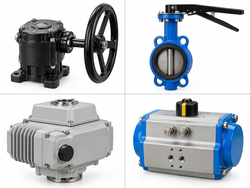
A gear actuator enquiry should state the output requirement and the conditions that limit the complete drive. For a RUITO valve package, include the valve construction, process medium, temperature and maximum closing differential pressure. Add power, control and installation information so the proposed gearing can be reviewed against the actual duty.
How can procurement keep the decision traceable?
Request the selected actuator configuration, an interface drawing, operating limits and the test basis used for approval. Keep any alternative gear material or reduction ratio visible as a technical deviation rather than allowing it to disappear into a general description. Retain the approved version for repeat orders and spares. This gives engineering a defined package to verify and gives purchasing a clear basis for comparing price, delivery and supplied documentation.
- Provide duty, load and available power.
- Approve interfaces, controls and performance limits.
- Keep substitutions and revisions visible.
Key takeaway: Order the configuration that was technically reviewed, with its performance conditions and interface details attached.
| Check | What to confirm |
|---|---|
| Enquiry inputs | Motion, load, duty, temperature and controls. |
| Approved output | Named configuration, drawings and test requirements. |
Send the valve duty, power supply and mounting details when you contact us. RUITO can review the drive arrangement with the valve and identify the information required for approval.
Frequently asked questions
Q1. Can I select a gear actuator by motor power alone?
No. Check the delivered motion, torque-speed behavior, duty and complete-drive limits.
Q2. Are steel gears always better than polymer gears?
No. Compare the actual design ratings and service conditions, including the mating gear and temperature.
Q3. Will a higher ratio always solve a torque problem?
No. It changes speed and travel, while input limits, efficiency and component capacities still apply.
Q4. Does position feedback prove the valve seals?
No. Feedback reports position at its sensing point; isolation performance needs the specified valve test.
Q5. What is the most useful information for a quotation?
Provide required motion, load profile, duty, ambient conditions, power, controls and the mounting drawing.