
Choose a valve gearbox by following the load from its input shaft to the valve stem, then checking the ratings at every connection. Similar housings can contain different reductions, output drives and stop arrangements. A parts list and a mounting drawing prevent an apparently suitable replacement from becoming a site modification.
Images are AI-generated illustrations of generic equipment configurations.
1. What does a valve gearbox do?
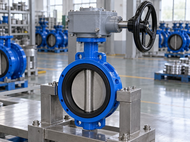
A valve gearbox changes the speed, torque or direction of the motion supplied to a valve. It may take input from a handwheel or a powered actuator. The required output depends on the valve mechanism: a butterfly disc needs part-turn rotation, while other valves may require multiple rotations or a thrust-producing drive.
Where does the load go?
Follow the input shaft through the gear train, bearings, output sleeve and coupling into the valve shaft. Reaction torque returns through the housing, mounting flange and supporting structure. That second path can be overlooked when a replacement has a suitable output bore but a weak bracket. Ask for both paths to appear in the assembly review, with capacities and interfaces tied to the same configuration rather than borrowed from different catalogue options.
- Identify the required output motion.
- Trace the torque and reaction paths.
- Check the complete configuration’s ratings.
Key takeaway: Review the drive as an assembly whose connections must carry the specified loads.
| Check | What to confirm |
|---|---|
| Driving path | Input, gears, output sleeve and valve shaft. |
| Reaction path | Housing, flange, fasteners and support. |
2. How do worm and sector gears work?
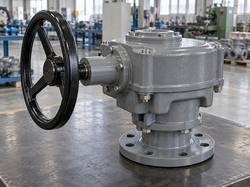
A worm-type valve gearbox uses a screw-like worm to drive a wheel or sector, producing substantial reduction in a compact arrangement. A sector only needs the teeth required for its permitted travel. For a butterfly valve, the output arrangement and stops must support the specified part-turn movement and seating method.
Which parts distinguish this arrangement?
The input worm rotates repeatedly as the output moves through a smaller angle. Bearings support the shafts and carry gear-generated loads, while the housing holds their alignment. Lubrication and tooth contact affect the relationship between input and output torque. During a parts enquiry, identify the exact gear set rather than ordering a wheel by its outside diameter; tooth geometry and the mating worm form a matched mechanical arrangement.
- Confirm wheel or sector construction.
- Record total ratio and permitted travel.
- Identify the mating gear set for service parts.
Key takeaway: Order worm-drive parts against the approved gearbox identity and drawing rather than a visual resemblance.
| Check | What to confirm |
|---|---|
| Worm input | Multiple turns supply the reduction. |
| Wheel or sector | Transfers the resulting motion to the output. |
3. Where do bevel and miter gears fit?
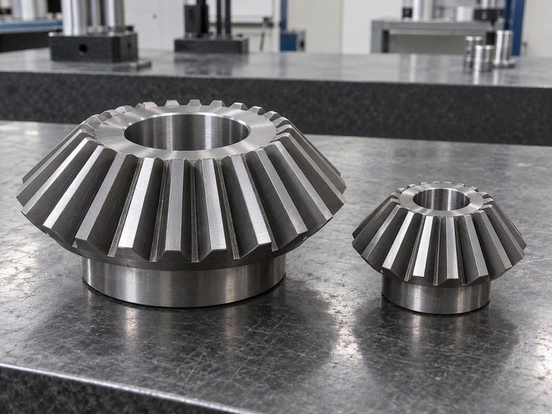
Bevel and miter arrangements in a valve gearbox transfer rotation between intersecting shafts. They can redirect an input where access requires a different handwheel position. Their suitability depends on the required motion and ratio; a right-angle change by itself does not establish the torque multiplication needed for the valve.
How do you avoid confusing direction with reduction?
A miter arrangement commonly describes equal-size bevel gears that redirect motion without changing the nominal ratio. Other bevel arrangements can provide reduction. A multi-turn valve drive may also include a stem nut and thrust bearings, which a quarter-turn butterfly valve drive does not automatically require. Confirm the exact output function on the drawing before treating two right-angle housings as interchangeable simply because both accept a handwheel at the side.
- Identify whether the gearing redirects or reduces motion.
- Check whether the output also carries thrust.
- Confirm travel requirements for the actual valve.
Key takeaway: Describe output motion and load explicitly when comparing right-angle gear arrangements.
| Check | What to confirm |
|---|---|
| Direction change | Relocates the input or output axis. |
| Reduction | Changes turns and available torque. |
4. When are spur gears useful?
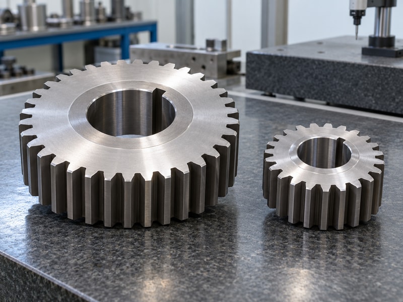
Spur gearing in a valve gearbox transfers motion between parallel shafts and can provide an additional reduction stage. It may form part of a larger drive rather than the complete valve operator. The number of stages, shaft positions and total reduction determine whether it fits the requested package.
What should the drawing identify?
Show the input and output shafts, the gears between them and any connection to a subsequent worm or other reduction stage. If a primary reduction unit is supplied separately, its mounting and input limits still belong in the calculation. More stages can change the package envelope, weight and permitted input speed. Compare the complete train’s output rather than multiplying catalogue ratios while assuming every stage has perfect efficiency.
- Include every reduction stage in the calculation.
- Check added weight and installation clearance.
- Use the approved complete-train performance data.
Key takeaway: Keep the primary reduction and the final valve drive within the same technical review.
| Check | What to confirm |
|---|---|
| Individual stage | Has its own ratio and losses. |
| Complete train | Determines the final output and package size. |
5. What changes with dual-input drives?
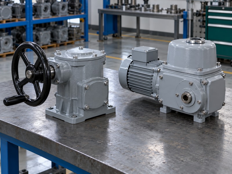
A dual-input valve gearbox provides more than one intended input arrangement, such as powered operation with a manual provision. The internal selection or isolation method must prevent an inappropriate load path. Two visible input connections do not establish that both may be driven at once or used without a changeover procedure.
What must the operating instructions explain?
Ask which input is active in each mode, what the operator must do before changing modes and whether the inactive input can move. The assembly may need interlocking, a clutch or another defined arrangement. Review the consequences of a powered start while someone is using the manual input. These checks belong to the actual drive design; adding a second shaft or an improvised handwheel does not create a suitable dual-input system.
- Identify permitted operating modes.
- Check isolation and changeover requirements.
- Document the condition of the inactive input.
Key takeaway: Approve the changeover method together with the mechanical arrangement and operating procedure.
| Check | What to confirm |
|---|---|
| Normal drive | State the selected power and control mode. |
| Alternate input | State isolation, engagement and operating limits. |
6. How does a manual override work?
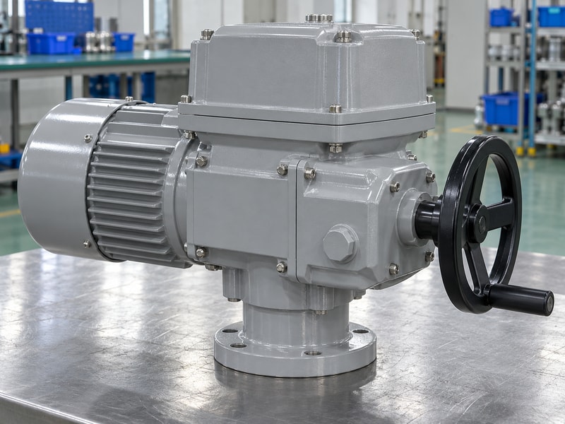
A manual-override valve gearbox allows specified manual operation when the normal powered drive is unavailable or isolated. Some designs are integral to an actuator, while others use a separate approved mechanism. The operator needs a clear engagement procedure and enough access to complete the required movement within the permitted effort.
What does an override need to achieve?
A manual provision must drive the actual valve through the required stroke, not merely rotate an unloaded mechanism during inspection. Confirm the expected operating load, wheel or wrench connection and permitted input force. Also establish how the normal drive is restored and how valve position is verified afterward. A manual override does not by itself cause the valve to move automatically to a safe position after loss of power.
- Check manual operation at the specified load.
- Confirm engagement and restoration procedures.
- Keep automatic fail action as a separate requirement.
Key takeaway: Specify what manual operation must accomplish and how the assembly returns to normal service.
| Check | What to confirm |
|---|---|
| Manual override | Requires an operator and an approved procedure. |
| Automatic fail action | Requires its own energy and control arrangement. |
7. How should you calculate valve gearbox output?
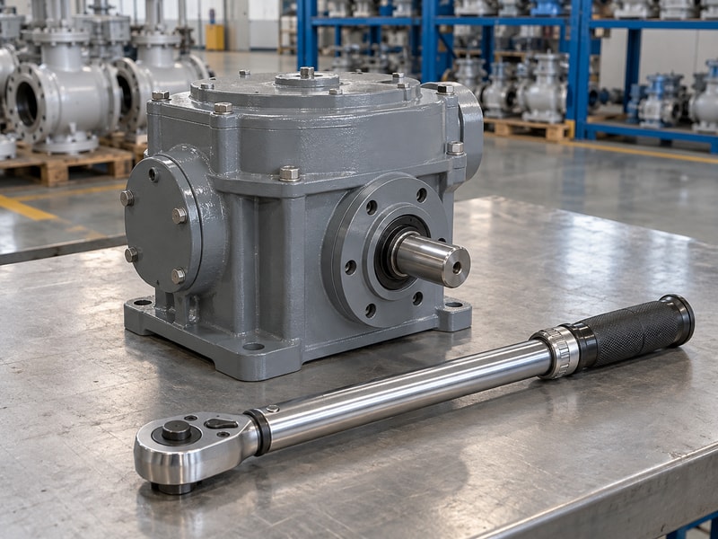
Calculate valve gearbox output from the approved input condition, total reduction and applicable efficiency, then compare it with the rated output capacity. Both checks matter because a calculated torque may exceed a component’s allowable load. Check the valve shaft and coupling limits before increasing input force to obtain more output.
How can a simple example expose a wrong assumption?
Suppose a preliminary calculation uses 15 N·m input torque, a 60:1 reduction and an assumed efficiency of 0.40. The resulting 360 N·m is an arithmetic estimate, not a catalogue rating. At the same ratio, a different efficiency changes that output, while a higher input may exceed the gearbox limit. Use the example to organize the supplier’s calculation, then replace assumptions with approved data for the selected valve duty.
- State the input torque and its source.
- Use a total ratio for all supplied stages.
- Compare calculations with each component’s rating.
Key takeaway: Do not approve the package until required torque and allowable loads can be compared on one sheet.
| Check | What to confirm |
|---|---|
| Illustrative estimate | 15 × 60 × 0.40 = 360 N·m. |
| Approval basis | Supplier data and component load limits. |
8. Which interfaces transfer the load?
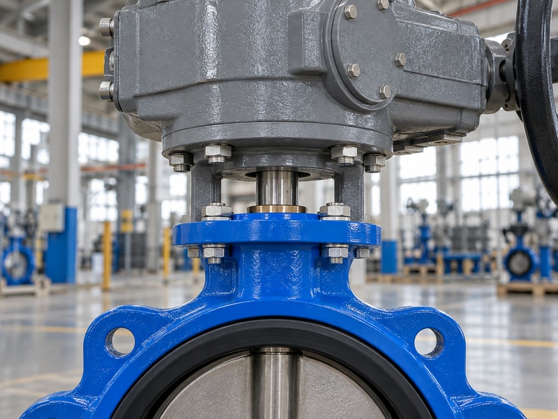
The valve gearbox interface transfers output torque through the coupling and reaction torque through the mounting structure. Its dimensions must match the valve topworks as well as the gearbox. An advertised mounting standard does not remove the need to verify the actual shaft form, register and fastener arrangement.
Which fit problems are easy to miss?
A coupling can bottom on the stem before the mounting faces meet, or engage only a short portion of a square shaft. A pilot may appear to fit while holding the parts off their proper faces. Thread type and bolt length can also differ between two assemblies with similar hole patterns. Check these dimensions on a sectioned assembly drawing and confirm the fit without using fasteners to force the components into alignment.
- Show coupling engagement and end clearance.
- Confirm registers, threads and fastener length.
- Check alignment before tightening the assembly.
Key takeaway: Use a complete interface review to prevent fit errors that photographs cannot reveal.
| Check | What to confirm |
|---|---|
| Coupling review | Engagement, bore geometry and clearance. |
| Mount review | Register, fasteners, alignment and stiffness. |
9. What limits service life?
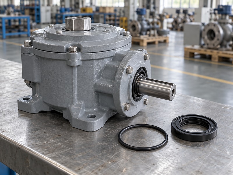
Valve gearbox service life depends on load, alignment, duty, lubrication and environmental protection acting together. Housing material or wheel material alone cannot predict it. A correctly selected gear train can still suffer premature damage when water enters the enclosure, a bracket flexes or a valve develops an uninvestigated obstruction.
Which observations help maintenance act early?
Record the original input effort, stroke turns and backlash where the supplier defines a measurement method. During inspection, compare like conditions rather than comparing an unloaded bench reading with a pressurized valve. Look for lubricant leakage, corrosion, loose fasteners and changed indication. If something has changed, isolate the assembly and investigate the cause before adjusting stops or applying more force; either response can hide the symptom while increasing damage.
- Keep a baseline under identified test conditions.
- Inspect sealing and mounting condition.
- Investigate changes before increasing input effort.
Key takeaway: Use recorded trends to direct inspection toward the valve, gearbox or mounting arrangement.
| Check | What to confirm |
|---|---|
| Mechanical influences | Load, alignment, duty and wear. |
| Exposure influences | Water, corrosion, temperature and lubricant condition. |
10. How should you specify a valve gearbox?
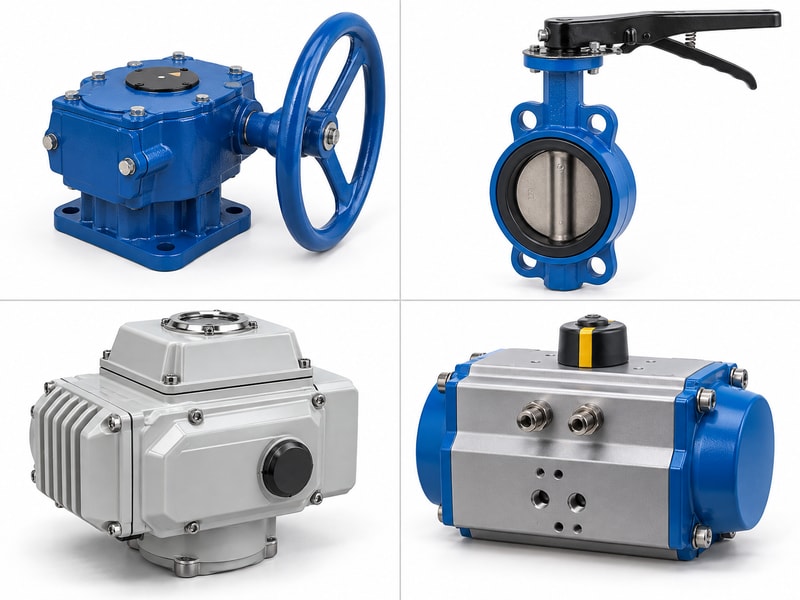
A valve gearbox specification should identify the output motion, valve duty, input arrangement and complete interfaces, with an agreed test and document package. RUITO can review these details alongside the valve selection. This gives procurement a defined assembly to compare rather than a general request for a gearbox of a particular size.
How do you make quotations comparable?
Ask each supplier to state the same input and output conditions, included adapters, environmental configuration and operating limitations. Request an assembly drawing and a clear list of supplied parts. Separate the gearbox’s mechanical acceptance from pressure and leakage acceptance for the valve. For repeat orders, retain approved revisions and require review of changes that affect fit, torque capacity, materials or operation, so a replacement remains tied to the original equipment record.
- List the complete scope and exclusions.
- Approve drawings and operating limits.
- Control revisions for repeat and spare-parts orders.
Key takeaway: Place the order against a traceable assembly and a common acceptance basis.
| Check | What to confirm |
|---|---|
| Quotation comparison | Same duty, interfaces and supplied scope. |
| Repeat supply | Approved revisions and controlled changes. |
Send the valve duty and mounting drawings when you contact us. RUITO can review the gearbox arrangement and the interfaces that need approval before the order is released.
Frequently asked questions
Q1. Can I replace a gearbox with one that has the same ratio?
Not on ratio alone. Check output capacity, shaft connection, mounting details, travel and input limits.
Q2. Do all right-angle gearboxes work the same way?
No. Worm, bevel and other arrangements can have different motion, load and reduction functions.
Q3. Can the manual override provide automatic fail-close action?
No. A manual override needs an operator; automatic fail action requires a separately specified arrangement.
Q4. How do I know whether the mounting flange fits?
Compare the actual bolt pattern, register, shaft geometry and coupling engagement on both drawings.
Q5. What should I retain for future spare parts?
Keep equipment identification, the approved assembly drawing, parts list, revisions and operating instructions.