
Choose a worm gear actuator by checking valve torque, permitted input effort, reduction ratio and the complete mounting interface. A handwheel that turns easily on a bench can still struggle against the specified closing differential pressure. Start with the valve duty and an approved torque calculation before comparing gearbox sizes.
Images are AI-generated illustrations of generic equipment configurations.
1. What does a worm gear actuator do?
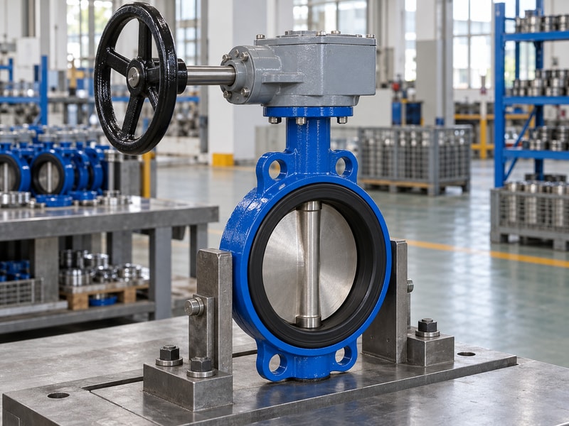
A worm gear actuator converts several turns of a handwheel into a slower, higher-torque movement at the valve shaft. On a butterfly valve, the output normally travels through roughly a quarter turn. The gearbox supplies the motion; the valve body, disc and seat still determine the permitted process conditions.
What problem does the gearbox solve?
You may have enough space for a lever yet still need more manageable operating effort at the worst closing differential pressure. A geared handwheel spreads that movement over more input turns, which can make manual positioning easier. It also adds parts, weight and travel time, so a small valve that operates comfortably with a lever may gain little from the conversion. Check accessibility during normal operation and maintenance before deciding that every valve needs gearing.
- Record valve construction and nominal size.
- Identify the maximum closing differential pressure.
- Confirm whether the duty requires manual operation.
Key takeaway: Use the gearbox to meet an operating requirement that you can state and verify.
| Check | What to confirm |
|---|---|
| Process isolation | Valve seat and disc provide shutoff. |
| Operating effort | Gear train changes input effort and travel. |
2. How does a worm gear actuator multiply torque?
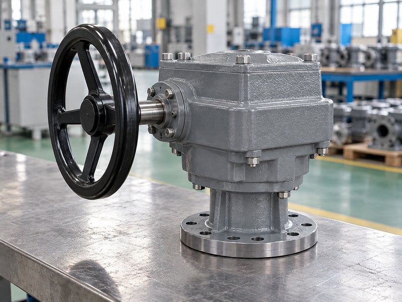
A worm gear actuator multiplies input torque through its ratio, with friction reducing the torque that reaches the output. For a preliminary calculation, output torque equals input torque multiplied by ratio and efficiency. Use the supplier’s actual performance data when approving a gearbox; a ratio alone does not establish its capacity.
How can you check a calculation?
Consider an illustrative handwheel with a 0.30 m diameter and a tangential rim force of 120 N. Its input torque is 18 N·m. If an assumed 80:1 ratio operates at an assumed efficiency of 0.35, the calculated output is 504 N·m. Those assumptions explain the arithmetic and are not a RUITO product rating; allowable input torque, output rating and valve shaft capacity must each support the selected arrangement.
- Keep force, radius and torque units consistent.
- Use efficiency for the specified load and condition.
- Check the rated input limit separately.
Key takeaway: Ask for the output calculation and its assumptions rather than accepting a ratio as a torque rating.
| Check | What to confirm |
|---|---|
| Illustrative input | 120 N × 0.15 m = 18 N·m. |
| Illustrative output | 18 × 80 × 0.35 = 504 N·m. |
3. Which worm gear actuator reduction ratio should you choose?
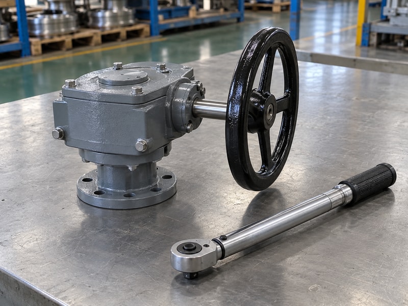
The reduction ratio for a worm gear actuator must balance handwheel effort against operating time and permitted input speed. A higher ratio usually means more turns for the same valve travel. Select it alongside the required output torque, wheel diameter and the time available for an operator to complete the stroke.
How many handwheel turns should you expect?
For a simple 80:1 reduction, one complete output revolution requires 80 input revolutions, so an ideal 90-degree movement takes 20 input turns. Additional reduction stages or a different travel angle change that figure. Ask the supplier to state turns from the approved open stop to the approved closed stop, then check the result on the assembled valve. A low handwheel force can become inconvenient if routine operation takes too many turns.
- Specify required output travel.
- Record the total reduction across all stages.
- Compare complete-stroke time at a realistic hand speed.
Key takeaway: Approve operating effort and stroke time together, using the assembled valve rather than an isolated gearbox.
| Check | What to confirm |
|---|---|
| Higher reduction | More input turns for the same output travel. |
| Wheel size | Changes rim force and required clearance. |
4. Can you rely on self-locking?
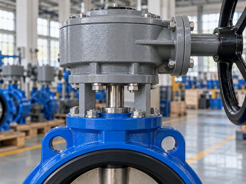
A worm gear actuator should hold position only under the conditions covered by its design and supplier’s instructions. Self-locking depends on geometry, friction and service conditions. Do not assume every worm drive will resist back-driving, or that a normally self-locking gearbox provides the positive restraint required for a particular safety function.
What should the supplier confirm?
Ask whether position holding applies at rest, across the specified temperature range and under the expected vibration. Lubrication and wear can change friction, while a powered input may introduce a different holding arrangement. If the application requires a lock, brake or other positive restraint, include that requirement in the purchase specification. An indicator showing a closed position confirms neither a locked shaft nor acceptable seat leakage, so keep those acceptance checks separate.
- State vibration and external loading conditions.
- Ask for position-holding limitations in writing.
- Specify a positive lock when the application requires one.
Key takeaway: Treat position holding as a documented function with defined limits, not an automatic property of the gear name.
| Check | What to confirm |
|---|---|
| Position holding | Confirm the applicable service conditions. |
| Positive restraint | Specify the required locking arrangement separately. |
5. Which mounting parts must match?
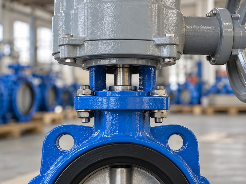
A worm gear actuator must match the valve’s mounting flange, shaft geometry, coupling engagement and torque reaction path. Matching a nominal flange designation is only one part of that check. The output bore and the valve shaft must transmit the specified torque without bottoming, slipping or imposing an unintended side load.
Which dimensions belong on the drawing?
Measure the bolt pattern, pilot or register, shaft projection, bore form and engagement length. Distinguish a square drive from a keyed round shaft even when their outside dimensions look similar. A bracket also needs adequate stiffness and fastener engagement to carry reaction torque. Review the valve’s topworks drawing with the gearbox drawing before machining an adapter; using bolts to pull misaligned components together can conceal a fit problem until the valve starts operating.
- Confirm shaft form and its angular orientation.
- Check fastener size, thread and engagement.
- Show coupling clearance and engagement on the drawing.
Key takeaway: Approve a complete interface drawing that identifies both mating parts and the load path between them.
| Check | What to confirm |
|---|---|
| Mounting flange | Bolt pattern, register and fastener details. |
| Shaft connection | Bore form, fit and engagement length. |
6. Can the gearbox accept a powered drive?
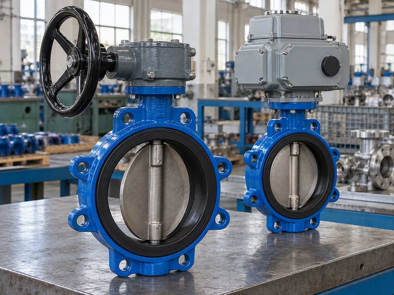
A worm gear actuator can accept a powered drive only when the gearbox is designed and rated for that input arrangement. A manual gearbox does not automatically become suitable for motor operation. Input speed, duty, mounting loads and control settings all need review before adding an electric multi-turn actuator or another drive.
What changes when a motor replaces the handwheel?
A person may stop turning after feeling an abnormal load; a powered drive needs a defined way to stop before damaging the mechanism. Confirm the maximum gearbox input torque and the permitted speed, then coordinate the actuator’s limit and torque settings with the valve seating instructions. Also check how manual operation is selected and whether the drive must be isolated before using the handwheel. The complete assembly needs its own functional acceptance record.
- Check permitted input speed and duty.
- Coordinate travel and torque limiting.
- Document the manual-operation procedure.
Key takeaway: Obtain approval for the complete powered package rather than attaching a motor to a manual-only gearbox.
| Check | What to confirm |
|---|---|
| Manual input | Wheel effort and access govern normal operation. |
| Powered input | Speed, duty and stopping controls require approval. |
7. Which enclosure suits the installation?
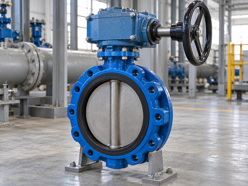
A worm gear actuator enclosure should suit the actual installation environment, including ambient temperature, water exposure and corrosion. A painted housing alone does not establish protection against submersion or chemical splash. Specify the exposure at the gearbox location, which may differ considerably from the fluid conditions inside the valve.
Which environmental details change the order?
An outdoor water-treatment installation may need protection against rain and condensation, while a coastal installation adds salt exposure and corrosion concerns. A buried arrangement needs its own sealing, operating connection and maintenance provisions. Keep those duties separate rather than describing every location as outdoor service. Ask the supplier to identify the coating, seal and lubricant selections that support the stated environment, including any maintenance conditions attached to the protection claim.
- State ambient minimum and maximum temperatures.
- Describe washdown, flooding or burial explicitly.
- Identify corrosion exposure and inspection access.
Key takeaway: Describe the exposure in the enquiry so the supplier can select and document a suitable configuration.
| Check | What to confirm |
|---|---|
| Fluid conditions | Limit the valve’s wetted and pressure parts. |
| Ambient exposure | Limits housing, seals, coating and lubricant. |
8. How should you manage lubrication?
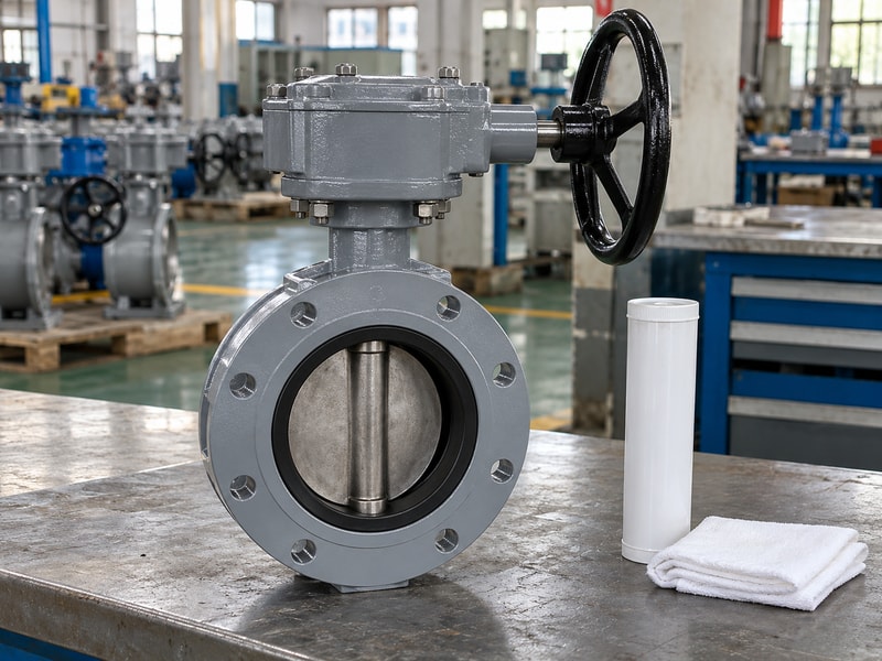
Lubrication for a worm gear actuator should follow the instructions for its exact gearbox and service duty. Some housings retain lubricant for long intervals; others need a stated inspection or replenishment schedule. Do not mix greases, add lubricant through an unidentified port or assume that more grease will correct an overloaded mechanism.
What should maintenance record?
Keep the approved lubricant identification with the equipment record, along with the quantity and replenishment method where the manufacturer specifies them. Inspect the housing and shaft entries for leakage, corrosion and damaged seals before opening anything. If operating effort rises, compare it with the original baseline and investigate the valve as well as the gearbox. A tight seat, obstructed disc or misaligned coupling can increase effort even when the gear train has adequate lubrication.
- Use the approved lubricant and compatibility instructions.
- Inspect seals before adding lubricant.
- Record changes in operating effort or backlash.
Key takeaway: Investigate the cause of a change in effort before treating it as a lubrication problem.
| Check | What to confirm |
|---|---|
| Routine inspection | Leakage, seals, corrosion and input effort. |
| Lubricant work | Approved type, method and recorded quantity. |
9. What should commissioning prove?
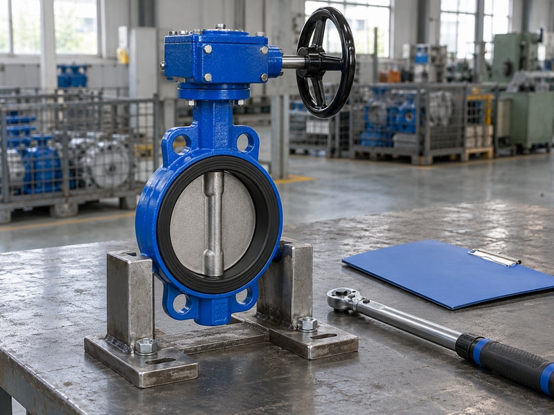
Commissioning a worm gear actuator should prove correct travel, indication and valve operation within the approved limits. Free movement on a dry bench is one check, while leakage performance and operation at the specified duty are different checks. Plan each test against an agreed procedure and record the assembled valve’s identity.
What should be checked before pressure is applied?
Confirm that the valve disc can move without striking the mating pipework or flange bore. Check the open and closed indications against the physical disc position, then set stops according to the valve instructions. Isolate and depressurize equipment before any adjustment or removal work. Pressure and leakage tests need their specified medium, direction, pressure, duration and acceptance criterion; an operator should not compensate for leakage by applying unapproved extra input force.
- Check disc clearance before cycling the assembly.
- Verify indication against physical travel.
- Record stop settings and functional results.
Key takeaway: Keep mechanical adjustment, functional testing and pressure-test acceptance as distinct recorded steps.
| Check | What to confirm |
|---|---|
| Mechanical check | Fit, clearance, travel and indication. |
| Performance check | Approved operating and leakage procedures. |
10. What should your purchase package contain?
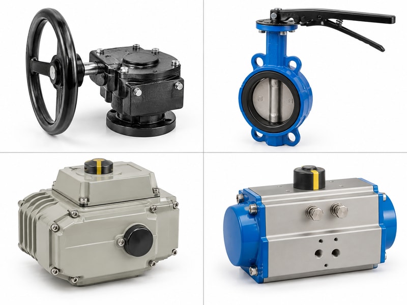
A worm gear actuator purchase package should connect the valve duty to a named gearbox configuration, approved interfaces and measurable acceptance requirements. RUITO can review the valve construction, process conditions and operating arrangement against the requested package. Send the duty information before asking for a gearbox chosen only by valve diameter.
What should you include with the enquiry?
Provide medium, operating temperature, maximum closing differential pressure, required operating frequency and the valve torque data. Add topworks drawings, wheel orientation, access restrictions and environmental exposure. For a replacement, include readable identification and measured dimensions alongside photographs. The quotation should list the selected configuration, supplied adapters, required tests and documentation, so you can compare offers on the same basis and identify exclusions before placing the order.
- Send the valve duty and torque information.
- Attach the complete mounting and access dimensions.
- Agree drawings, tests and delivery documents.
Key takeaway: Request a reviewed valve-and-drive package with traceable drawings and an agreed acceptance plan.
| Check | What to confirm |
|---|---|
| Technical submission | Duty, torque, interfaces and operating limits. |
| Order acceptance | Approved configuration, tests and documentation. |
Send your valve duty, torque data and topworks drawing when you contact us. RUITO will review the configuration and identify the interface details needed before manufacture.
Frequently asked questions
Q1. Can I choose the gearbox by valve size alone?
No. Size identifies the valve, but torque also depends on construction, differential pressure, materials and operating conditions.
Q2. How do I know whether the ratio is suitable?
Check both the required rim force and complete-stroke turns using the supplier’s performance data.
Q3. Can I add a motor to my manual gearbox?
Only after the supplier confirms the input speed, torque, duty and mounting arrangement for powered operation.
Q4. Does self-locking mean I can omit a lock?
Not automatically. Ask whether the specified holding and safety functions require a separate positive restraint.
Q5. What should I send for a replacement quote?
Send the identification, torque duty, mounting drawing, shaft dimensions and photographs of the existing assembly.