
Choose a gear operated butterfly valve when the documented valve duty and permitted manual effort support a reduction operator. Compare it with a lever using the same torque, operating-time and access requirements. A diameter rule alone leaves those decisions unresolved.
Two quotations list the same valve size and pressure class, but one includes a lever and the other a gearbox. The cheaper option may need excessive hand force, while the geared option may take too long for the intended local task. Review both complete arrangements before choosing the operating method.
1. How does a gear operated butterfly valve differ?
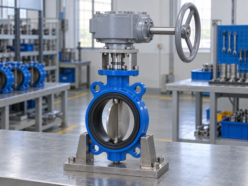
A gear operated butterfly valve places a reduction mechanism between the handwheel and the valve shaft, while a direct lever moves with that shaft. Reduction changes the relationship between manual input and output rotation. Both arrangements still need the valve disc, seat and body configuration selected for the actual medium and operating conditions.
What should a useful comparison hold constant?
Compare the same valve duty. Keep medium, temperature, pressure differential, body connection and acceptance requirements identical while evaluating the operators. Otherwise a lighter handwheel movement or lower price may reflect a different valve configuration instead of a better operating method. RUITO selects valve and drive arrangements against application information; the operator choice remains one part of the defined valve assembly.
- Compare gear and lever options against identical duty.
- Keep body, seat and connection differences visible.
- Identify the actual operator supplied with each valve.
Key takeaway: Compare complete valve assemblies with the same application requirements before judging the operating method.
| Check | What you should confirm |
|---|---|
| Lever | Manual movement acts directly through the shaft connection |
| Gear | Reduction connects input turns with smaller output rotation |
| Comparison | Valve configuration and process duty remain explicit |
2. What duty needs a gear operated butterfly valve?
A gear operated butterfly valve is appropriate when actual torque demand, permitted input effort and operating requirements justify manual reduction. Valve diameter contributes to the selection but cannot define a universal changeover point from lever to gear. Seat design, medium, temperature and closing differential can alter the operating demand for valves of similar size.
Which operating cases should engineering supply?
Describe the demanding case. Include normal operation, maximum permitted closing differential and any direction or duty change that affects required torque. Obtain breakaway, running and seating information for the selected valve rather than borrowing a value from another product. Your team can then compare permitted manual effort and operator capacity against the same documented demand across both quotations.
- Provide medium, temperature and closing differential.
- Request torque information for the selected valve.
- State the intended movement frequency and operating cases.
Key takeaway: Use actual valve demand to decide whether direct lever operation remains suitable.
| Check | What you should confirm |
|---|---|
| Application | One configuration defines medium and operating limits |
| Demand | Selected valve data describe torque through the stroke |
| Choice | Permitted effort and duty guide the operator decision |
3. What effort suits a gear operated butterfly valve?
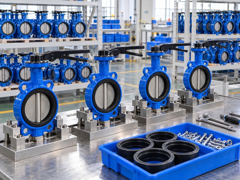
A gear operated butterfly valve should meet the project handwheel-effort requirement without exceeding input, output or valve-component limits. A lever needs its own effective length and force review. Gear reduction can lower required input torque, subject to actual efficiency, but a ratio label alone cannot supply a reliable hand-force figure.
How should force and torque be compared?
Keep units and application points clear. Tangential force at an effective radius relates to torque at that same input point; it does not directly describe output at the valve shaft. Compare actual wheel or lever dimensions, permitted manual force and supplier operator data, then check the complete load path. A longer lever or larger wheel can also permit more input torque than the selected arrangement allows.
- Compare force at the actual wheel or lever radius.
- Keep input torque distinct from valve-shaft torque.
- Check permitted input and connected-component limits.
Key takeaway: Approve manual effort alongside the complete torque chain and actual grip dimensions.
| Check | What you should confirm |
|---|---|
| Force | Effective grip radius and permitted effort are defined |
| Transmission | Actual operator data support the input-output comparison |
| Limits | Input, output and valve components retain their ratings |
4. What speed suits a gear operated butterfly valve?
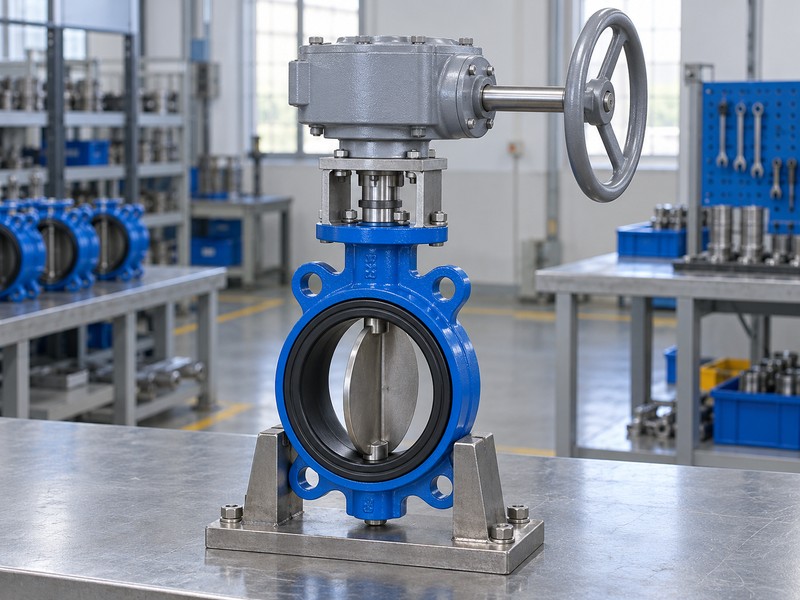
A gear operated butterfly valve usually needs multiple handwheel turns for its accepted valve stroke, while a direct lever follows the shaft rotation without reduction. The actual turn count depends on the complete operator and required output travel. Neither arrangement receives an acceptable operating time from a generic catalogue comparison alone.
What does the motion chart help distinguish?
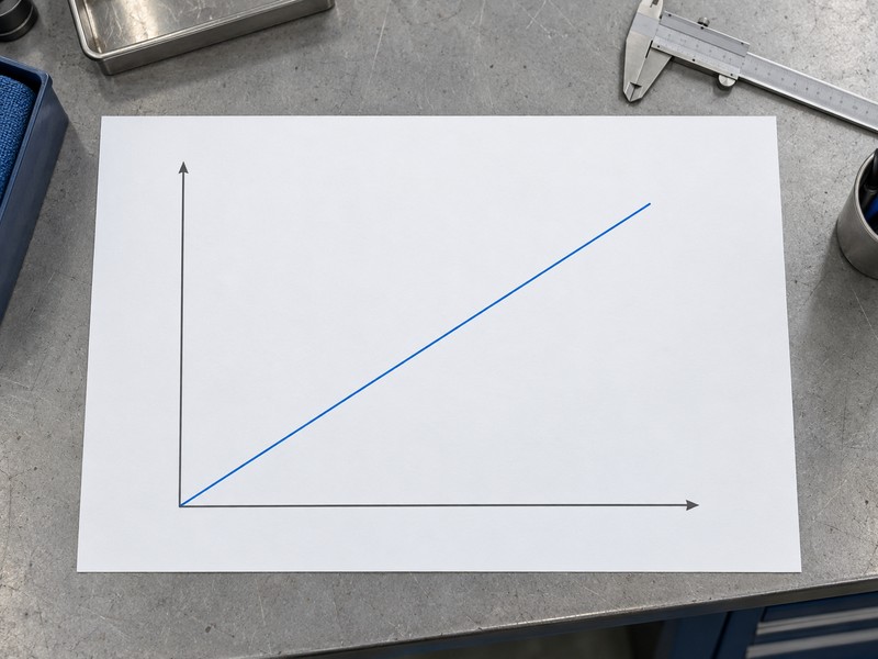
Compare like movement quantities. The chart shows ideal fixed-ratio input turns against shaft angle, without measured operating time or torque data. For a defined angular ratio i, ideal turns equal i times output degrees divided by 360, so turns for a full output revolution differ from turns for a quarter-turn stroke. Use actual operator and task information when evaluating operation time or any required closure behaviour.
- Identify complete reduction and accepted output travel.
- Use actual turn data for the selected operator.
- Review operating time against the specific local task.
Key takeaway: Compare accepted movement and actual task timing before choosing a manual operating method.
| Check | What you should confirm |
|---|---|
| Movement | Lever and handwheel inputs have different relationships |
| Turns | Complete ratio and output angle define ideal motion |
| Timing | Actual task and operator data govern the comparison |
5. What access suits a gear operated butterfly valve?
A gear operated butterfly valve needs wheel clearance, hand access and adequate space for service around the complete installed assembly. A lever needs its own sweep and grip clearance. A wheel can solve one reach problem while introducing additional height or cover-removal constraints, so compare the actual installed envelopes before approval.
Which site dimensions should the reviewer request?
Locate the operator in its surroundings. Include pipe centreline, adjacent equipment, guarding, supports and the operator standing area rather than reviewing a valve outline in isolation. Keep internal disc clearance against the mating pipe and flange bores as a separate valve installation check. An extension or chainwheel arrangement changes the package and needs its own selected support, load and operating-access information.
- Compare complete wheel and lever movement envelopes.
- Include operator reach, standing area and maintenance access.
- Review extensions and chain arrangements as selected configurations.
Key takeaway: Choose an operating method that fits the actual working and maintenance space.
| Check | What you should confirm |
|---|---|
| Operation | Grip and movement clear actual surrounding equipment |
| Service | Required cover or component withdrawal space remains |
| Pipeline | Internal disc clearance receives a separate review |
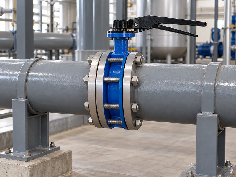
6. What holding suits a gear operated butterfly valve?
A gear operated butterfly valve needs documented holding and position-retention behaviour for its intended loads. A worm mechanism name cannot guarantee universal self-locking, and a lever latch has its own selected design and limitations. Request the applicable retained-position or locking requirements instead of assuming either arrangement automatically meets the project need.
Does a pointer make throttling suitable?
Separate indication from process performance. A pointer shows the indexed mechanism position, while suitable throttling depends on the selected valve characteristics and operating conditions. Neither a fine scale nor gear reduction establishes flow accuracy, cavitation resistance or stable control at every opening. If the project requires intermediate operation, ask for the actual valve application limits and the operator holding information for that duty.
- Request selected holding and locking limitations.
- Keep pointer indication separate from flow performance.
- Review intermediate-position duty with actual valve data.
Key takeaway: Specify retained-position and process-control needs independently of the visible operator features.
| Check | What you should confirm |
|---|---|
| Retention | Selected limits address the required held position |
| Indication | Pointer references the indexed assembly position |
| Process | Throttling suitability follows actual valve and duty data |
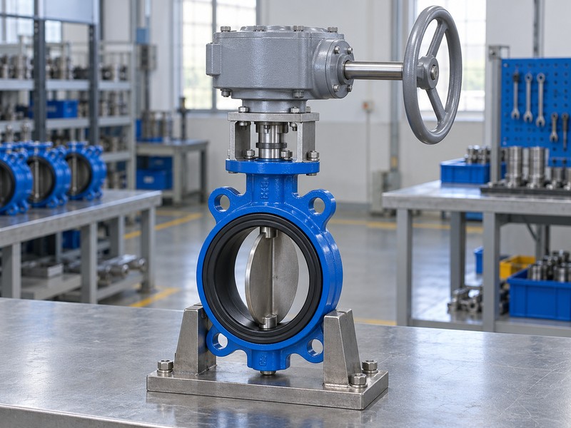
7. What controls suit a gear operated butterfly valve?
A gear operated butterfly valve operated manually at a handwheel does not by itself provide remote commands, automatic movement or a defined failure action. A lever has the same need for an operator at the valve. Where the application requires powered control, select a compatible arrangement with its supply, feedback and operating requirements explicitly defined.
What changes when powered operation is considered?
Describe the required function. Identify local or remote commands, position feedback, movement frequency and any required response to supply loss before selecting the drive package. ISO 5211 concerns part-turn attachments; it does not establish those control functions. The complete powered arrangement still needs its own torque, interface, supply and applicable environmental or hazardous-area information.
- State local, remote and automatic operating needs.
- Define feedback and any required failure action.
- Review powered packages as complete selected arrangements.
Key takeaway: Choose manual or powered operation from the required function and complete package evidence.
| Check | What you should confirm |
|---|---|
| Manual | An operator acts at the lever or handwheel |
| Powered | Supply and control functions need their own definition |
| Interface | Mounting scope does not establish control behaviour |
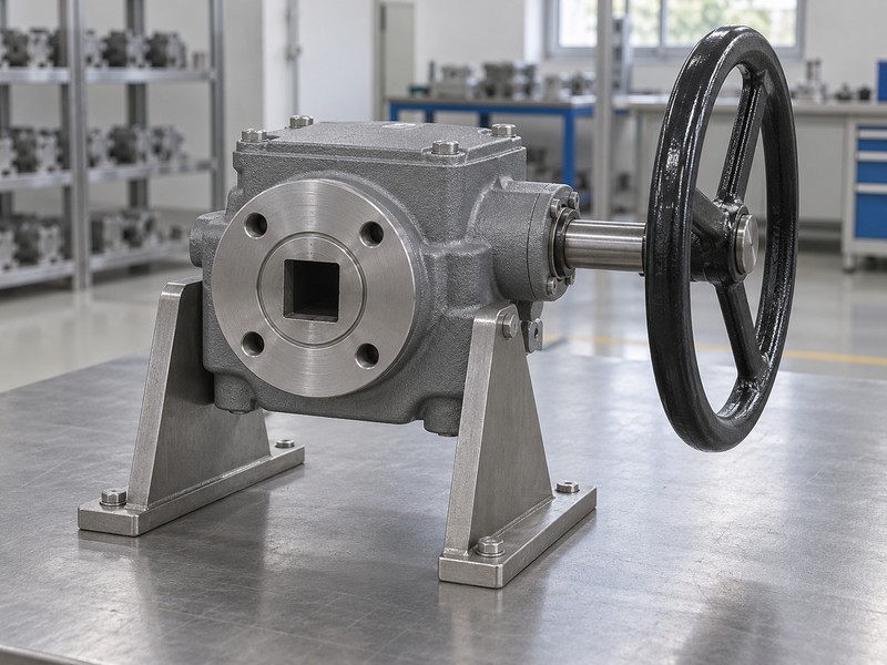
8. What materials suit a gear operated butterfly valve?
The materials and pressure-temperature limits of a gear operated butterfly valve follow the actual valve configuration, with separate external requirements for its operator. Choosing gear operation does not change an elastomer seat into a chemical-resistant lining or raise the body pressure rating. Keep wetted materials and operator exposure within their own stated selection boundaries.
Which connection differences affect the comparison?
Retain the exact valve description. Wafer, lug and flanged bodies have different installation details, while seat and lining choices follow actual medium compatibility and operating conditions. Compare each option with the same intended connection and acceptance scope before assigning a cost difference to the operator. A gearbox also adds its selected mounting and drive interfaces, which need dimensional and load review alongside the valve connection.
- Retain actual wetted materials and temperature-pressure limits.
- Compare identical body connection and acceptance requirements.
- Review operator exposure separately from the valve medium.
Key takeaway: Keep valve construction and operator selection explicit when comparing complete assemblies.
| Check | What you should confirm |
|---|---|
| Valve | Materials and ratings belong to one actual configuration |
| Connection | Selected body form has its own installation details |
| Operator | Mounting, drive and external exposure receive review |
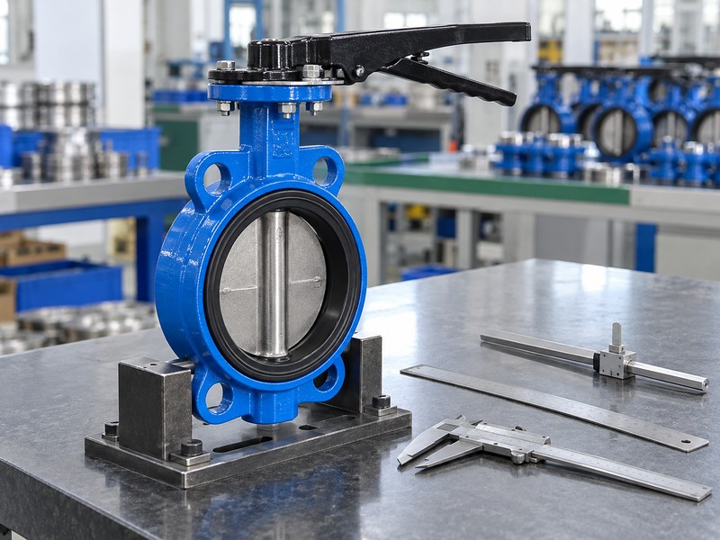
9. What upkeep suits a gear operated butterfly valve?
Maintenance for a gear operated butterfly valve follows the selected valve and operator instructions, actual duty and recorded condition. A lever has fewer transmission components but still needs its own connection and condition checks. Compare the real service scope and parts support instead of assuming that one operating method has no maintenance requirements.
What should a cost comparison include after purchase?
Compare the installed work. Include access for inspection, the selected lubrication policy, available spare parts and the records required after an affected replacement. Obtain current commercial and delivery information for the actual package rather than using a generic service-life promise. The initial price difference may be small compared with the cost of an incompatible drive, awkward access or a replacement that cannot be identified from the asset record.
- Compare selected service requirements and inspection access.
- Request actual spare and replacement support information.
- Include fit and documentation in the installed-cost review.
Key takeaway: Compare service and replacement needs for the complete installed assembly.
| Check | What you should confirm |
|---|---|
| Service | Selected instructions define actual maintenance provisions |
| Support | Parts and replacement scope are explicitly confirmed |
| Cost | Installed work and access join the purchase-price comparison |
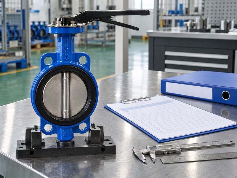
10. What selects a gear operated butterfly valve correctly?
Select a gear operated butterfly valve after valve duty, torque, manual effort, operating time, access and required functions have been compared with the lever alternative. Identify the selected valve, operator and supplied mounting components in the offer. Retain the accepted configuration so purchasing receives a defined package and later maintenance can trace the installed arrangement.
What should the decision record explain?
State the reason for the choice. Record which requirement the geared arrangement satisfies, where the lever alternative falls short and what exceptions still need closure. Retain the accepted general arrangement, drive details, torque basis and selected operating information with the order. RUITO can review valve-assembly options against supplied conditions, while the final choice should remain traceable to the actual project requirements and accepted documents.
- Compare each operating method against the same requirements.
- Identify the selected valve, operator and mounting parts.
- Close exceptions and retain the reason for the choice.
Key takeaway: Choose the operating method that meets the defined task and keep the supporting decision record.
| Check | What you should confirm |
|---|---|
| Requirements | Duty, effort, timing and access share one basis |
| Selection | Chosen package and technical exceptions are defined |
| Record | Accepted documents explain and preserve the decision |
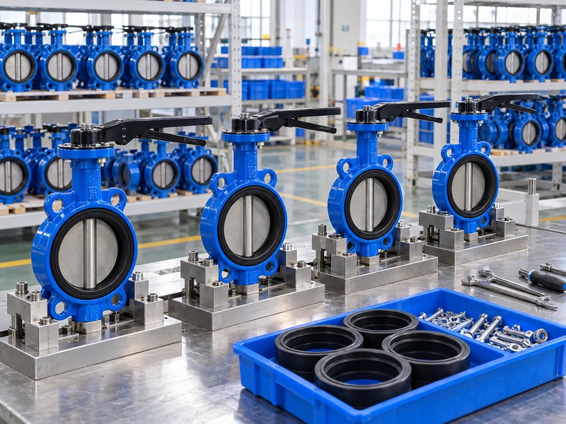
Send RUITO the valve duty, permitted manual effort, operating-time requirements and installation envelope. We can review gear and lever options for the proposed valve assembly and identify the documents needed for comparison. Contact us before approving an operating method from diameter alone.
FAQ
Q1: Can I choose gear operation from diameter alone?
No. Use actual valve torque, differential pressure, permitted manual effort, timing and installed access.
Q2: What’s the best choice for rapid local movement?
Compare the actual task. A direct lever can move quickly, but acceptable effort and system closure requirements still govern the choice.
Q3: Can a gearbox guarantee that water hammer disappears?
No. System transients depend on operating conditions and closure behaviour, which need their own project review.
Q4: How do I know whether the valve can throttle?
Request selected valve data. A gearbox or position scale alone cannot establish stable control or suitable process limits.
Q5: Can I add a powered actuator later?
Only after a complete package review. Check compatibility, torque, supply, controls, mounting and the required operating functions.