
Fix gear operated high performance butterfly valve selection mistakes by matching the valve body, seat, drive and installation with one approved duty sheet. A handwheel may turn easily during inspection yet become difficult under closing differential pressure. Use the checks below when discussing a gear operated high performance butterfly valve requirement with your supplier, then request the drawings and operating limits for the offered configuration.
1. What is a gear operated high performance butterfly valve?
A gear operated high performance butterfly valve combines a quarter-turn butterfly valve with a manual reduction gearbox. The handwheel drives the gearbox input shaft while its output turns the valve stem. In industrial product ranges, high-performance commonly describes an offset disc and a purpose-designed sealing arrangement; the description alone gives no working-pressure or temperature guarantee.
Your purchase specification needs two linked descriptions. One defines the valve, including its pressure-containing body, disc, stem, seat and packing. The other defines the operator, its output rating, mounting arrangement and permitted input effort. A matching bolt pattern answers only part of that review.
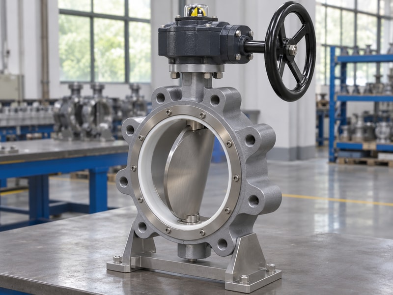
Separate valve duty from the manual drive
A replacement gearbox also needs an approved coupling and verified travel. A complete assembly should move through its specified stroke without binding, with indication checked against actual disc position. Ask the supplier to record that check before shipment, especially when a bracket or extension stem changes the original assembly.
- Identify the valve configuration and revision.
- Specify maximum closing differential pressure.
- Match the operator and coupling with the stem rating.
| Item | What it establishes | What still needs checking |
|---|---|---|
| Valve data sheet | Offered construction | Duty-specific limits |
| Gearbox rating | Permitted operator load | Stem and mounting strength |
| Position indicator | Operator reference | Actual disc indexing |
Keep these records together so a later operator change does not lose the valve’s operating limits.
2. How does the gearbox change handwheel effort?
The gearbox on a gear operated high performance butterfly valve trades additional handwheel turns for lower input effort. Gear ratio, efficiency and wheel radius all affect that effort. The operator’s rated output and allowable input remain separate limits, so fitting a larger wheel requires the manufacturer’s approval.
Consider an illustrative sizing check in which the approved output demand is already 400 N·m. With a 50:1 ratio and an assumed efficiency of 0.35, calculated input torque is about 22.9 N·m. A 0.20 m wheel radius gives approximately 114 N tangential rim force. These figures explain the calculation; they do not select a gearbox for your valve.
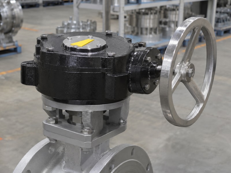
Check the force calculation and its assumptions
Actual starting friction, service temperature, duty frequency and manufacturer allowances must enter the selection. Request the supplier’s stated efficiency basis and output rating rather than calculating available torque from gear ratio alone. Evaluate access as well: an operator cannot apply the intended rim force if a wall blocks half the wheel.
- Record required output torque and its duty conditions.
- Check permissible input torque and rim force.
- Confirm wheel clearance throughout operation.
| Input | Illustrative value | Use |
|---|---|---|
| Output demand | 400 N·m | Approved example demand |
| Ratio and efficiency | 50:1 and 0.35 | Input torque calculation |
| Wheel radius | 0.20 m | Rim-force calculation |
Replace every illustrative value with the offered assembly’s approved data.
3. How do offset geometry and seating affect selection?
Offset geometry changes how a gear operated high performance butterfly valve disc approaches and leaves its seat. Double-offset and triple-offset designs have different sealing geometry. Materials and torque requirements still need checking for the exact configuration. Ask for the construction drawing and leakage acceptance criteria instead of treating both descriptions as interchangeable.
A polymer seat in a high-performance valve does not make the valve a fully polymer-lined chemical valve. The body, stem, disc, packing and other exposed parts still need a materials review. Likewise, a metal seat does not establish zero leakage under every test or operating condition.
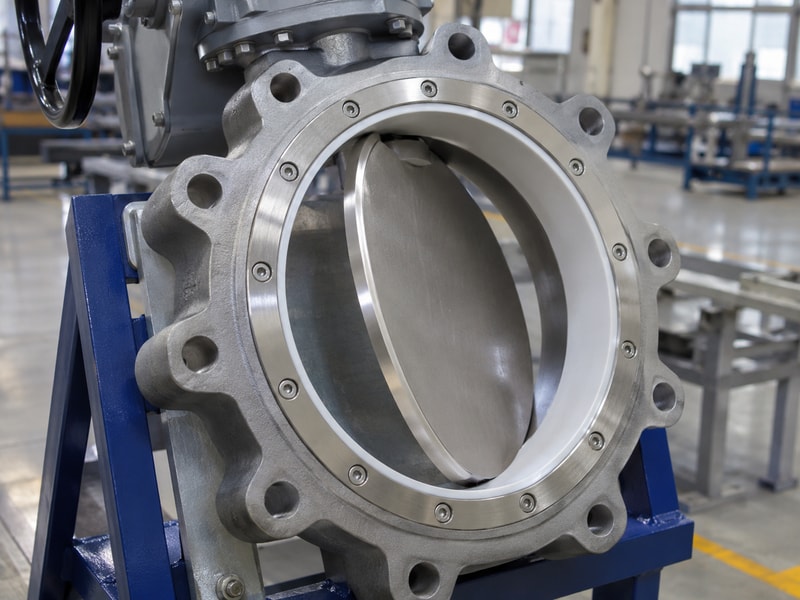
Read the sealing arrangement as an assembly
Compare the offered seal design with the actual fluid, shutdown temperature and specified leakage requirement. For a water project, separately declared forward and reverse differential-pressure limits may determine installation direction. For a hot process duty, request the configuration’s pressure–temperature information and thermal qualification; a cold water test cannot supply that evidence.
- Identify every wetted component and auxiliary seal.
- State leakage criteria, direction and test medium.
- Check whether a listed feature is standard or optional.
| Description | Required evidence | Frequent purchasing gap |
|---|---|---|
| Double offset | Approved section drawing | Geometry assumed from appearance |
| Polymer seat | Complete materials list | Seat confused with full lining |
| Metal seat | Defined leakage acceptance | Universal tight-shutoff promise |
Resolve the sealing arrangement before comparing nominal valve prices.
4. Which gear operated high performance butterfly valve body fits?
Choose a gear operated high performance butterfly valve body by its approved connection, face-to-face dimension and installed disc clearance. Wafer, lug and double-flanged bodies require different checks. A shared nominal size does not prove that a replacement will fit the existing pipework.
For a wafer butterfly valve, check the mating flange bore and nearby pipe geometry against the disc’s swept envelope. For a lug body, confirm thread form, engagement length and bolting arrangement. End-of-line service needs a separate approved rating and installation arrangement.
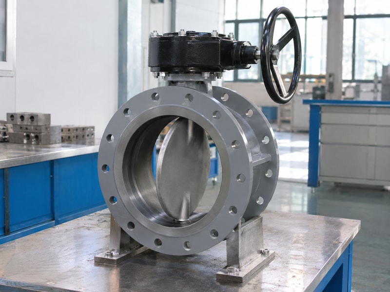
Verify the complete installation envelope
For a flanged butterfly valve, compare flange drilling, facing and face-to-face dimensions with the project drawing. Include wheel reach, gearbox orientation and removal space. A fit review should show where the valve, supports and adjacent fittings will sit before the order is released.
- Obtain the actual mating-flange details.
- Review disc sweep at full permitted opening.
- Check installation and later maintenance access.
| Body route | Check before ordering | Document |
|---|---|---|
| Wafer | Bore and disc clearance | Installation drawing |
| Lug | Threads and permitted end duty | Bolting and rating details |
| Double flanged | Facing, drilling and length | Approved assembly drawing |
Use measured site dimensions when replacing an installed assembly.
5. Which materials suit the operating medium?
Materials for a gear operated high performance butterfly valve must suit the complete fluid composition and operating conditions. A body alloy or seat name cannot establish compatibility for the whole assembly. Include additives, cleaning fluids, solids and shutdown conditions in the review.
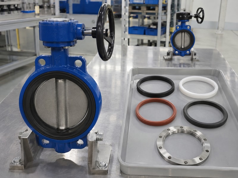
RUITO’s supplied product information separates water, compatible mineral oil, clean gas and lined chemical configurations. Those boundaries prevent a water-service seal from being substituted into an oil or chemical order. For example, an EPDM water configuration cannot automatically replace an approved NBR oil configuration.
Keep application claims within the confirmed configuration
The same discipline applies to high-performance enquiries. Provide fluid concentration, normal and maximum temperature, operating pressure and maximum closing differential pressure. If the requested medium or rating falls outside an offered product’s documented scope, obtain a separate engineering decision before issuing a purchase order. Market terminology cannot fill a missing material qualification.
- List complete fluid composition and cleaning cycles.
- Identify body, disc, stem, seat and packing materials.
- Require written approval for substitutions.
| Duty input | Why the supplier needs it | Requested response |
|---|---|---|
| Fluid composition | Wetted-material review | Configuration-specific acceptance |
| Maximum temperature | Seal and pressure limits | Coupled operating limits |
| Solids or deposits | Wear and obstruction assessment | Stated service restrictions |
Keep the approved materials list attached to repeat orders.
6. What torque data should the supplier provide?
Specify a gear operated high performance butterfly valve using starting, running and seating torque at the declared duty conditions. The gearbox must provide the approved demand while the stem, coupling and mounting remain within their allowable loads. Nominal diameter alone cannot establish that match.
Ask which differential pressure and temperature underlie each torque value. Check whether the supplier has already included its required design allowance. Applying another unexplained multiplier can hide the assumptions, while omitting an allowance can leave the operator undersized.
Review the weakest mechanical limit
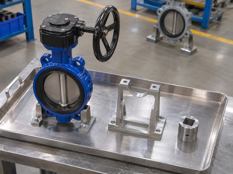
Also ask how the assembly prevents overtravel and excessive operator input. A larger gearbox does not increase the permissible stem torque. Replacement brackets and couplings need their own dimensional and strength review, even if the original operator still bolts onto them. Record the accepted combination as one assembly so spare-parts purchasing retains that match.
- Obtain torque values with their calculation conditions.
- Compare gearbox output with each mechanical limit.
- Confirm manufacturer-approved stops and input limits.
| Component | Load to review | Evidence |
|---|---|---|
| Gearbox | Required output and allowed input | Operator selection sheet |
| Stem and coupling | Transmitted torque | Approved mechanical limits |
| Bracket and fasteners | Assembly reaction loads | Mounting drawing and calculation |
Reject a selection sheet that states only the gearbox ratio.
7. What installation checks prevent disc interference?
Install a gear operated high performance butterfly valve only after checking flange alignment, bore clearance and the manufacturer’s prescribed disc position. Follow the exact installation manual for gaskets, tightening and travel verification. Generic opening percentages or bolt torques cannot replace that procedure.
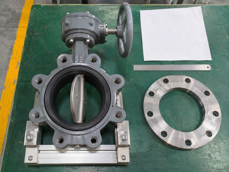
Inspect the pipe opening for weld intrusion, debris and obstructions. Check that supports carry the intended pipe and valve loads rather than forcing an assembly into misalignment. An adjacent reducer or fitting can interfere with disc travel even when both mating flanges have the correct drilling.
Confirm free movement before commissioning
Verify indication against actual disc position before the line is put into service. If operation binds, stop and inspect the installation using the manufacturer’s procedure. Do not use handle extensions to force the wheel. Removal, drive work or internal inspection requires the approved isolation, depressurization and decontamination arrangements.
- Check pipe bore and nearby fittings.
- Review gasket and flange instructions for the exact body.
- Record the permitted full-stroke check before startup.
| Observation | Possible issue | Appropriate next step |
|---|---|---|
| Binding during travel | Disc interference or misalignment | Stop and inspect |
| Indicator mismatch | Coupling or indexing error | Verify assembly position |
| Poor access | Wheel envelope overlooked | Resolve layout before service |
Retain the commissioning record with the approved installation drawing.
8. Which inspection records support acceptance?
Accept a gear operated high performance butterfly valve against its agreed inspection plan and product-specific records. Separate shell integrity, seat leakage, external leakage and functional checks. Each record should identify the tested valve, procedure and acceptance conditions.
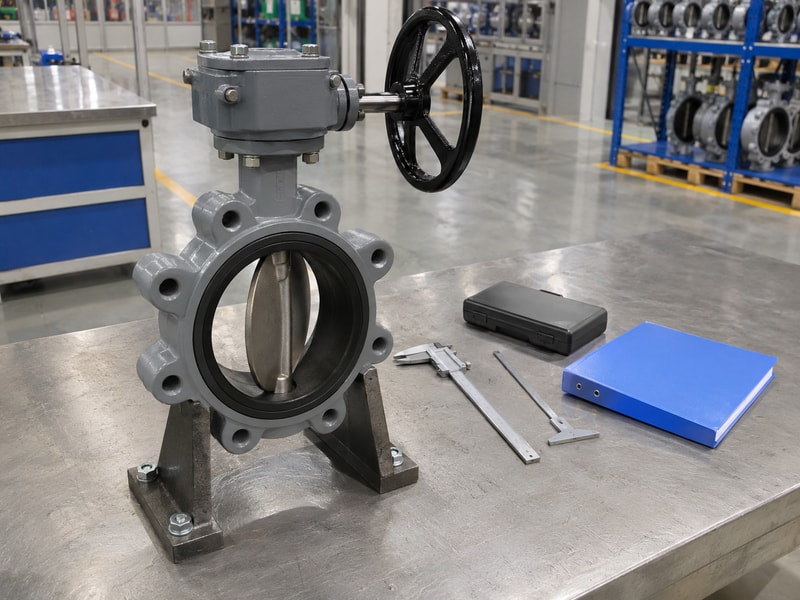
Check test medium, pressure, direction, duration and leakage criterion together. A photograph of a gauge cannot establish those conditions. Nor can the shell-test pressure be used as the valve’s allowed working pressure. Product marking, material traceability and the final assembly revision should agree with the records.
Compare like-for-like test conditions
For RUITO’s documented water-service double-flanged double-offset range, forward and reverse closing limits are declared separately by configuration. Do not transfer a successful forward test into a higher reverse-service claim. Additional requirements such as fire performance, emissions or special media need their own applicable qualification evidence.
- Match records with the product ID and approved configuration.
- Check instruments and acceptance criteria.
- Close deviations before release.
| Record | What to match | Acceptance question |
|---|---|---|
| Shell test | Valve ID and procedure | Was the required test completed? |
| Seat test | Direction and leakage criterion | Does it cover the specified duty? |
| Functional check | Final operator assembly | Were travel and indication verified? |
Request the missing record before accepting a broad performance statement.
9. What should your enquiry include before purchase?
An enquiry for a gear operated high performance butterfly valve should define process duty, installation interfaces and acceptance requirements together. This gives the supplier enough information to identify a suitable configuration or declare a technical deviation before manufacture.
Include fluid data, coupled temperature and pressure conditions, closing differential pressure, connection details and required operating effort. Add the inspection plan, document list, spare-parts requirements and delivery milestones. Separate factory release from transport and customs time when assessing the schedule.
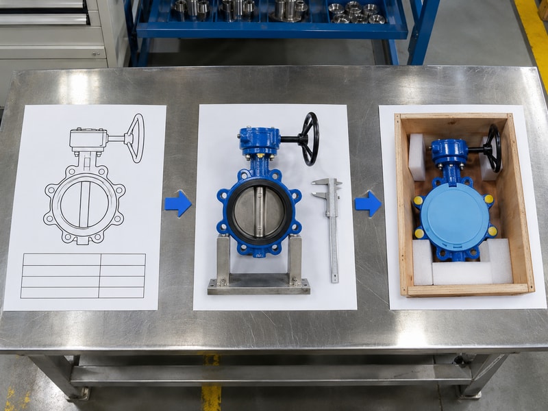
Release one controlled technical package
RUITO’s company and engineering information describes configuration-based selection and controlled project documentation. Send your duty sheet, mating-flange drawing and acceptance criteria when you contact us. Ask for a written response covering the proposed construction, operating limits, operator match and every unresolved deviation before you approve the order.
- Freeze the accepted drawing and materials revision.
- Identify approval and inspection hold points.
- Agree how later changes will be authorized.
| Enquiry item | Required decision | Purchase-order attachment |
|---|---|---|
| Duty sheet | Configuration fit | Accepted data sheet |
| Interface drawing | Installation fit | Approved assembly drawing |
| Inspection requirements | Release evidence | Agreed inspection plan |
Approve production after the technical response and order attachments agree.
10. What else should you check before operating the valve?
Operate a gear operated high performance butterfly valve within its approved duty and installation instructions. These questions address common gaps during replacement and handover.
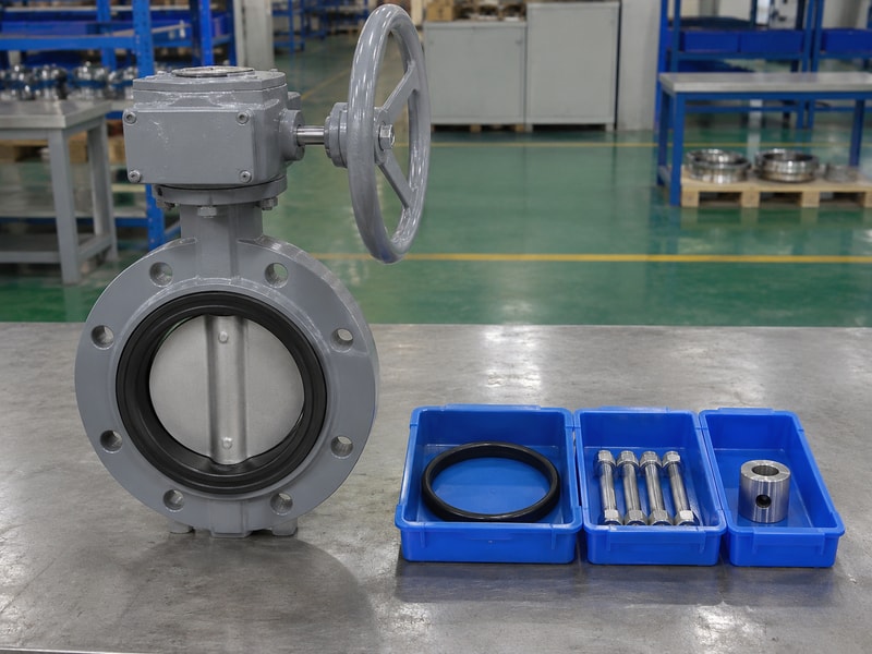
Q1: Can I replace the gearbox with a larger model?
Only with an approved mechanical review. Check stem torque, coupling, mounting, input limits and stops together.
Q2: Can I assume the valve seals equally in both directions?
No. Use the offered configuration’s declared forward and reverse limits and the corresponding acceptance records.
Q3: How do I know whether a replacement fits my pipework?
Compare the actual mating flanges, face-to-face dimension and swept disc envelope with the approved installation drawing.
Q4: Does a polymer seat make the valve suitable for chemicals?
No. Review every wetted material against the complete fluid composition, temperature and cleaning conditions.
Q5: What should I do if the handwheel becomes difficult to turn?
Stop and follow the site’s approved troubleshooting and isolation procedure. Extra leverage can overload the drive or stem and conceal interference.