
Maintain worm gear operators by tracking operating effort, sealing condition, alignment and backlash against the original assembly record. A new lubricant or a replacement wheel will not correct every fault. Investigate changes across the valve and its drive, then follow the exact gearbox instructions for inspection, repair and return to service.
Images are AI-generated illustrations of generic equipment configurations.
1. How do worm gear operators trade force for travel?
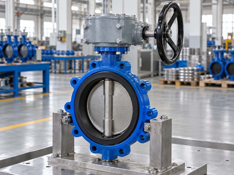
Worm gear operators exchange more input travel for greater usable output torque, with friction reducing the mechanical advantage. That tradeoff explains why a handwheel may need many turns to move a butterfly disc through a quarter turn. Maintenance should preserve the approved operating relationship rather than judging condition from handwheel effort alone.
What baseline should be recorded?
Keep the valve duty, gearbox ratio, wheel diameter and expected stroke turns with the equipment identity. Record initial operating effort under a stated condition, such as an approved unloaded or loaded check. Future comparisons need the same conditions because process differential pressure or valve condition can change the effort independently of gearbox wear. Also retain the final travel and indication settings so a later adjustment can be compared with the original accepted assembly.
- Retain ratio, wheel size and stroke-turn information.
- Record the conditions behind an effort measurement.
- Keep travel and indication settings with the equipment record.
Key takeaway: Create a baseline that lets maintenance distinguish a changed duty from a changed mechanism.
| Check | What to confirm |
|---|---|
| Motion baseline | Ratio, stroke turns and output travel. |
| Condition baseline | Effort, test conditions and indication settings. |
2. How do worm gear operators turn ratio into usable output?
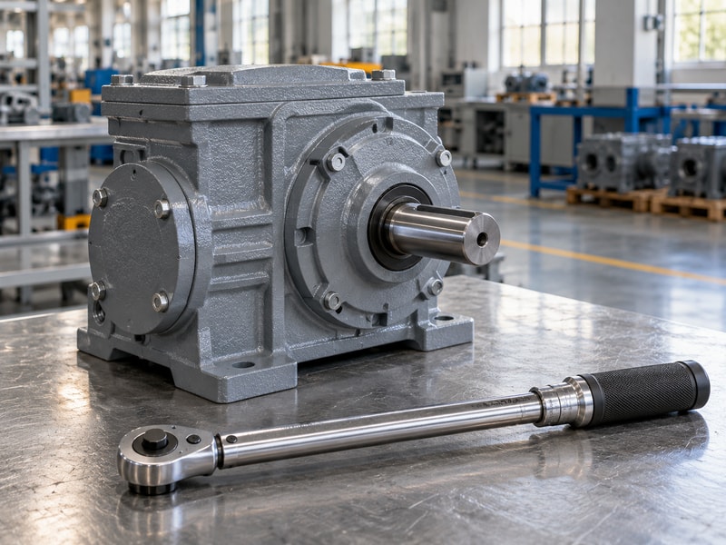
Worm gear operators turn ratio into useful output through a mechanism whose efficiency depends on design and operating conditions. Ratio describes relative movement, while efficiency affects usable torque. A maintenance assessment should not infer either current efficiency or remaining torque capacity merely from the ratio stamped on the housing.
How can a calculation prevent a false diagnosis?
For an illustrative 70:1 reduction, an assumed 0.30 efficiency gives a torque multiplication of 21 before considering the rest of the assembly. The same ratio at an assumed 0.40 efficiency gives 28. These figures explain why ratio and mechanical advantage differ; they are not measured efficiencies for the installed unit. If effort changes, compare the actual duty and approved performance data before deciding that the gear train has lost a particular percentage of efficiency.
- Distinguish movement ratio from torque multiplication.
- Keep assumed values separate from measured data.
- Use the supplier’s approved performance basis.
Key takeaway: Use calculations to organize evidence rather than inventing a condition rating for an untested gearbox.
| Check | What to confirm |
|---|---|
| Illustrative case A | 70 × 0.30 = 21 torque multiplication. |
| Illustrative case B | 70 × 0.40 = 28 torque multiplication. |
3. What changes in the worm and wheel contact?
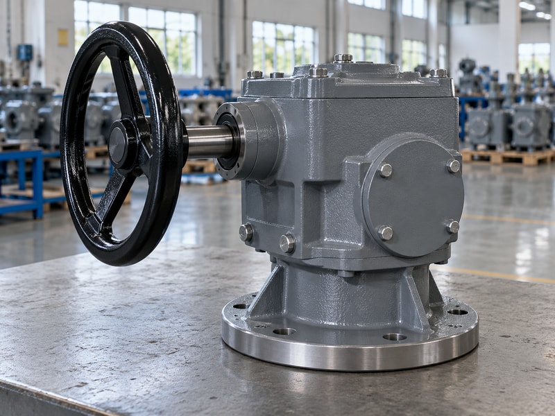
Contact in worm gear operators depends on the mating tooth geometry, alignment, lubricant and applied load. Wear or damage should be assessed against the manufacturer’s inspection criteria. A visible surface mark does not identify its cause or establish whether an individual worm, wheel or sector can be replaced independently.
What should be preserved during inspection?
After isolating and supporting the equipment as required, follow the approved procedure for access to the mechanism. Record the location and appearance of damage before cleaning removes useful evidence. Keep the mating parts identified, along with bearing positions and any observations about lubricant or contamination. Ask the manufacturer to interpret findings that lack an approved acceptance limit, and confirm whether repair requires a matched set, additional support components or complete gearbox replacement.
- Follow the exact access and inspection procedure.
- Record damage before altering the evidence.
- Confirm approved repair scope for mating parts.
Key takeaway: Connect tooth-condition findings with the complete gear pair and its support arrangement.
| Check | What to confirm |
|---|---|
| Inspection evidence | Location, appearance, contamination and mating parts. |
| Repair decision | Manufacturer’s criteria and approved replacement scope. |
4. When can self-locking fail to hold position?
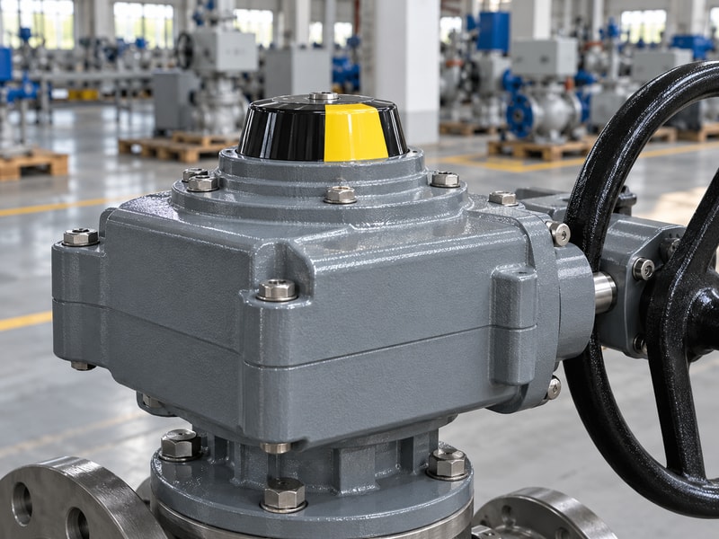
Position holding in worm gear operators depends on their design and specified service conditions. A self-locking description should not be treated as a positive mechanical lock for every load, vibration or lubrication condition. Review the installed duty if the valve moves unexpectedly or if the project requires a defined locked position.
Which observations need escalation?
Record unintended movement, changed indication, vibration and any recent maintenance before adjusting the assembly. Verify whether the motion came from the valve shaft, a loose coupling or the indicator itself. Keep positive locking or braking requirements explicit in the equipment specification. A change in lubricant or a repaired gear set should be reviewed against the original holding requirement, and return-to-service checks should include that function where it forms part of the approved duty.
- Record actual movement and the point where it occurred.
- Check coupling and indication separately.
- Reconfirm any specified position-holding function after repair.
Key takeaway: Investigate unexpected movement through the load path and the documented holding requirement.
| Check | What to confirm |
|---|---|
| Self-locking claim | Has design and service-condition limits. |
| Required locked state | Needs the specified restraint and verification. |
5. Which lubrication instructions should you follow?
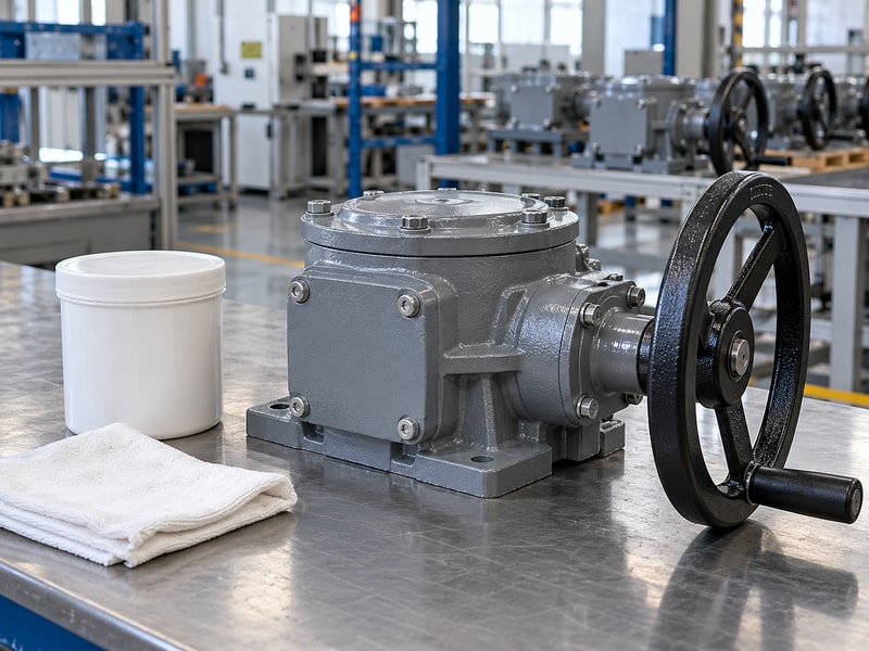
Lubrication for worm gear operators must follow the approved lubricant, method and interval for the exact unit and service duty. Do not assume that all enclosed housings use the same grease or replenishment method. A maintenance plan should identify what may be inspected externally and what requires an authorized opening procedure.
What should the lubricant record say?
Record lubricant identification, the work performed and the equipment condition at the time of service. Where the manufacturer specifies a quantity or fill procedure, follow it rather than adding grease until movement feels easier. Check compatibility before any substitution or mixing. If lubricant has leaked, inspect the relevant seal or joint and investigate the cause; replenishing a leaking housing without correcting the defect can leave the internal mechanism exposed to contamination again.
- Use the identified lubricant and approved method.
- Review compatibility before substitutions.
- Investigate leakage before routine replenishment.
Key takeaway: Tie lubrication work to the exact gearbox instructions and the observed condition of its seals.
| Check | What to confirm |
|---|---|
| Service instructions | Type, method, quantity and interval where specified. |
| Condition findings | Leakage, contamination and sealing defects. |
6. How do seals protect the mechanism?
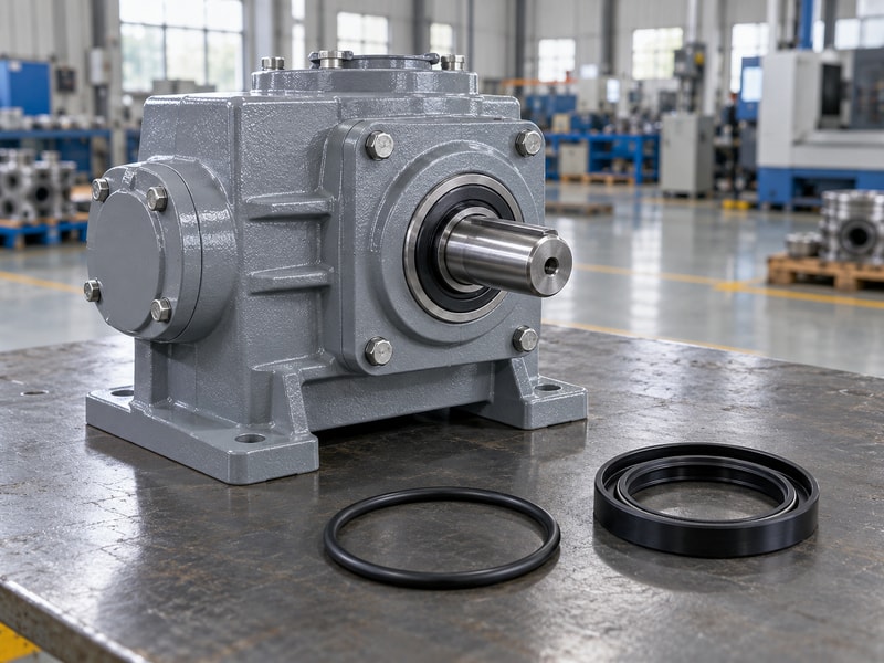
Seals in worm gear operators retain lubricant and limit entry of water or other contamination at the relevant joints and shafts. Their condition affects the protection of the internal mechanism. Inspect the complete exposure path, including input extensions and cover joints, rather than checking only the most visible housing surface.
Which environmental changes should be reviewed?
A relocated assembly may experience washdown, flooding, condensation or corrosion that was absent at the original installation. Record those changes and check the enclosure configuration against the new exposure. Look for damaged shaft entries, loose covers and corrosion around fasteners using the approved inspection method. An external coating repair does not restore a damaged internal seal, so identify which protection function was affected before deciding what maintenance work is required.
- Inspect shaft entries, joints and external connections.
- Record changed exposure conditions.
- Distinguish coating damage from seal failure.
Key takeaway: Review the sealing arrangement against the environment the gearbox encounters in service.
| Check | What to confirm |
|---|---|
| Retention function | Keeps the specified lubricant within the housing. |
| Exclusion function | Limits contamination through defined interfaces. |
7. How should you inspect worm gear operators for wear?
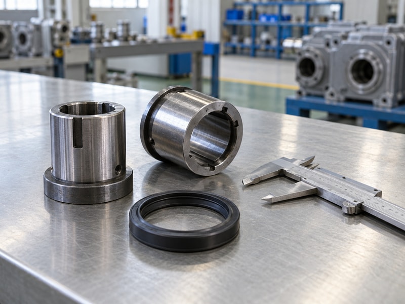
Inspect worm gear operators for wear and backlash using the manufacturer’s method and acceptance criteria, with the valve and coupling conditions identified. Backlash is lost motion between reversals, but a plant observation may include movement in several connections. Do not assign all visible free movement to the gear teeth without checking those connections.
How do you make repeated measurements comparable?
Identify where input and output movement are observed, the direction of loading and whether the assembly is unloaded or restrained by the valve. Check loose wheel connections, coupling fit and mounting condition before interpreting the internal mechanism. Record the method and conditions with each measurement. If no acceptance limit exists in the maintenance documents, request one from the responsible supplier rather than inventing a universal allowable angle for every gearbox size and design.
- Use a defined measurement point and method.
- Check external connections before attributing internal wear.
- Compare results with the exact approved criterion.
Key takeaway: Measure a defined part of the drive under repeatable conditions before deciding that wear is unacceptable.
| Check | What to confirm |
|---|---|
| Possible external movement | Wheel hub, coupling or mounting connection. |
| Possible internal movement | Gear contact and support within the gearbox. |
8. Which adaptation errors cause repeated damage?
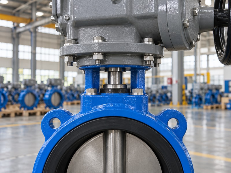
Adaptation errors can damage worm gear operators when couplings engage poorly, shafts are forced out of alignment or brackets deflect under reaction torque. Repeated failures at the same valve position require a review of the mounting assembly. Replacing internal parts alone can leave the original load problem unchanged.
Which dimensions deserve a second look?
Compare the as-installed shaft projection, coupling engagement, register fit and fastener stack with the approved drawing. Look for signs that a coupling bottomed before the mounting faces met or that bolts were used to pull the assembly into alignment. Confirm bracket stiffness and any added extension loads. If a retrofit changed the mounting height or orientation, include that change in the investigation and retain the corrected as-supplied drawing after the cause has been resolved.
- Compare actual assembly dimensions with the drawing.
- Check coupling engagement and axial clearance.
- Review bracket and extension loads.
Key takeaway: Inspect the mounting and coupling arrangement when a gearbox repeatedly suffers similar damage.
| Check | What to confirm |
|---|---|
| Geometric causes | Misalignment, bottoming or short engagement. |
| Load-path causes | Bracket movement or unsupported external connections. |
9. When should you repair or replace the gearbox?
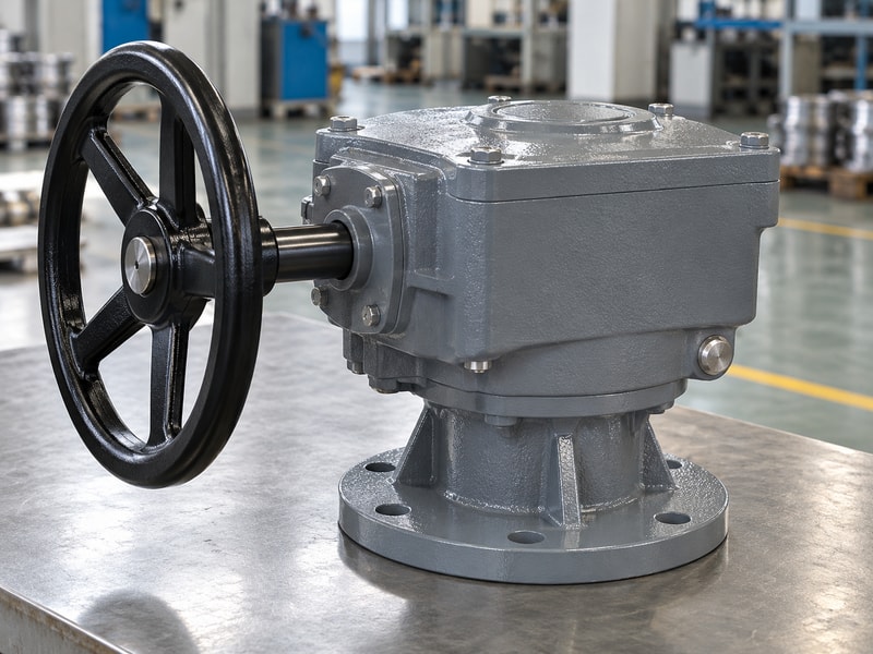
Repair or replacement of worm gear operators should follow the inspection findings, parts availability and the manufacturer’s approved service scope. Compare the condition of the complete mechanism and its interfaces. A low price for one replacement component may be misleading if several mating or support parts also need attention.
What should the decision compare?
Ask which parts can be replaced independently, which require a matched set and which inspections or tests are needed afterward. Include the cost and time for dismantling, alignment, reassembly and acceptance. Confirm that a proposed replacement gearbox preserves the required input limits, travel, output connection and environmental configuration. If the original unit is no longer available, treat an alternative as an assembly change with its own interface review rather than accepting a similar-looking housing as equivalent.
- Obtain the approved repair and test scope.
- Compare complete repair and replacement work.
- Review alternative configurations before ordering.
Key takeaway: Choose the option that restores a defined, verifiable assembly within the required service schedule.
| Check | What to confirm |
|---|---|
| Repair option | Approved parts, inspection and reassembly scope. |
| Replacement option | Confirmed duty, fit, limits and acceptance tests. |
10. Which records should maintenance retain?
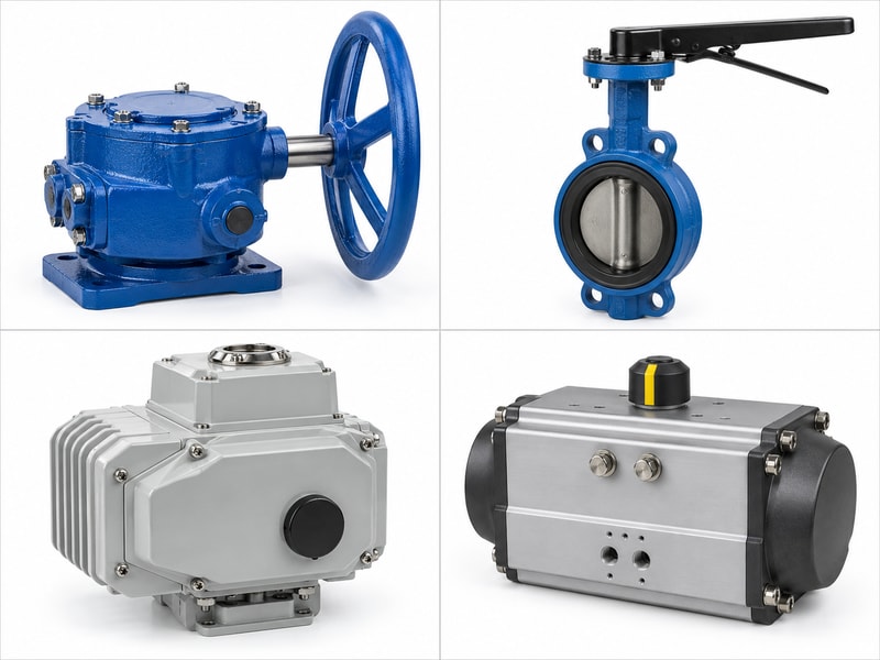
Maintenance records for worm gear operators should connect the findings, work and final checks to the exact valve-and-drive assembly. RUITO can review the valve duty and interface information for a requested replacement package. Retain sufficient evidence for the next inspection or order to begin from the accepted configuration.
What should be handed back to the equipment owner?
Include equipment identities, relevant drawing revisions, observed symptoms, inspection findings, replacement parts and lubricant work. Add final travel settings, indication checks and the acceptance results required by the repair procedure. Record unresolved limitations rather than describing the unit as restored without a defined basis. Keep the maintenance history with the valve data so later staff can distinguish a change in operating duty from a recurring mechanism or mounting problem.
- Identify the assembly and all parts replaced.
- Record findings, work and final checks.
- Retain limitations and approved configuration changes.
Key takeaway: Hand over a record that explains what changed and how the repaired or replacement assembly was verified.
| Check | What to confirm |
|---|---|
| Work history | Symptoms, findings, parts and lubricant service. |
| Return-to-service record | Configuration, settings and acceptance results. |
Send the gearbox identity, valve duty and inspection findings when you contact us. RUITO can review the valve package and the interface information needed for a matching replacement arrangement.
Frequently asked questions
Q1. Should I add grease when the handwheel becomes harder to turn?
Investigate the cause first. Compare duty, valve condition, alignment and lubricant instructions before adding anything.
Q2. Does visible free movement prove the worm wheel is worn?
No. Check the wheel hub, couplings and mounting connections as well as the internal mechanism.
Q3. Can I use the same inspection limit for every gearbox?
No. Use the exact manufacturer’s method and acceptance criteria.
Q4. Should a damaged wheel always be replaced alone?
No. Confirm whether its mating worm and support components require a matched repair scope.
Q5. What should I check after a repair?
Verify the specified fit, travel, indication, operating limits and any required holding or loaded function before return to service.