
Test geared butterfly valves by checking assembly fit, disc travel, operating effort and the specified pressure and leakage performance separately. Easy handwheel movement does not prove correct isolation. Agree the valve configuration, duty and acceptance procedure before inspection so each result answers a defined engineering question.
Images are AI-generated illustrations of generic equipment configurations.
1. How do geared butterfly valves operate?
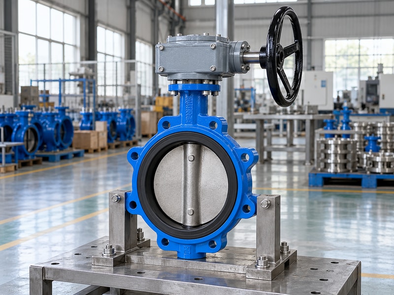
Geared butterfly valves use a gearbox to turn the stem and disc through the required part-turn movement. The input handwheel normally needs multiple revolutions for that travel. The gearbox controls how effort reaches the stem, while the valve body, disc, shaft and seat determine the permitted process and isolation performance.
What should inspection identify first?
Record the exact valve construction, nominal size, materials, pressure-temperature limits and operator arrangement. Distinguish wafer, lug and flanged connections because their installation checks differ. Confirm that the supplied gearbox and mounting parts match the approved configuration. A general product name is insufficient for acceptance when the order includes a specific seat material, shaft connection, operating direction or environmental requirement that affects the assembled package.
- Identify the valve and operator configuration.
- Check construction, materials and interfaces.
- Use the approved order and drawing revisions.
Key takeaway: Begin acceptance with the exact configuration that engineering approved.
| Check | What to confirm |
|---|---|
| Valve identity | Construction, size, materials and process limits. |
| Drive identity | Gearbox, coupling, mounting and operating arrangement. |
2. Which parts of geared butterfly valves control isolation?
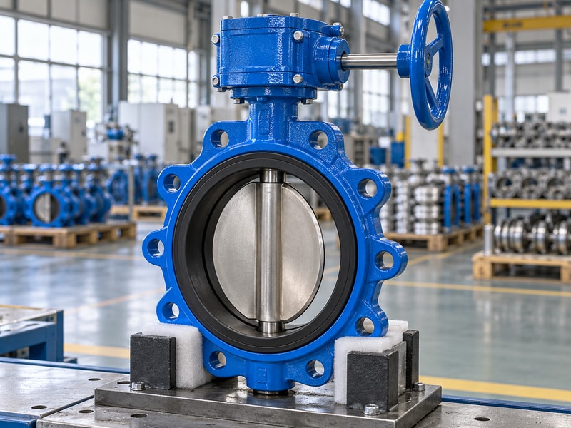
The disc, seat and shaft arrangement in geared butterfly valves controls how the valve moves and isolates the fluid. The body supports the pressure-containing assembly, while bearings and shaft retention maintain the required geometry. A gearbox replacement does not correct an unsuitable seat material or extend the valve’s permitted differential pressure.
Which parts should be checked against the duty?
Review the complete wetted-material configuration and the supplier’s stated operating limits. For a resilient-seated design, inspect the seat and disc condition using the approved method without damaging their sealing surfaces. Check shaft retention and the relationship between physical disc position and the output coupling. If the valve uses an offset or lined construction, follow its own requirements rather than transferring inspection or seating assumptions from a different butterfly valve type.
- Verify complete wetted materials and service limits.
- Inspect sealing surfaces using the approved method.
- Check shaft retention and physical disc position.
Key takeaway: Inspect the valve’s isolation components independently of the handwheel’s apparent ease of movement.
| Check | What to confirm |
|---|---|
| Isolation components | Disc, seat and the applicable sealing arrangement. |
| Supporting components | Body, shaft support and retention features. |
3. Which gear arrangement fits quarter-turn motion?
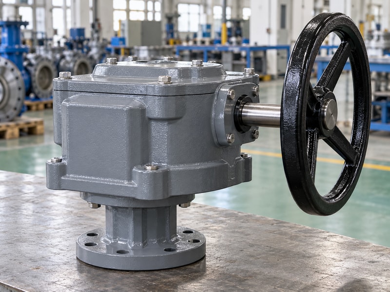
The gear arrangement for geared butterfly valves must deliver the specified limited-angle rotation and torque without exceeding assembly limits. A worm wheel or sector can provide suitable reduction, depending on design. Confirm the actual travel, input arrangement and stop method rather than assuming that any right-angle gearbox is suitable.
What should the supplier state?
Ask for total ratio, turns across the required stroke, maximum input torque and rated output capacity for the selected configuration. Include wheel diameter and direction of operation. If a powered input is used, add speed, duty and control requirements. These values let inspection compare the supplied unit with the approved calculation and help the owner understand how it should be operated without relying on a handwheel size or a generic description of manual gearing.
- Confirm ratio, travel and complete-stroke turns.
- Check rated input and output limits.
- Include power and duty requirements where applicable.
Key takeaway: Tie the gearbox’s motion and ratings to the exact valve assembly.
| Check | What to confirm |
|---|---|
| Motion specification | Travel, ratio, turns and operating direction. |
| Load specification | Input limit and usable output capacity. |
4. How do you match torque and manual effort?
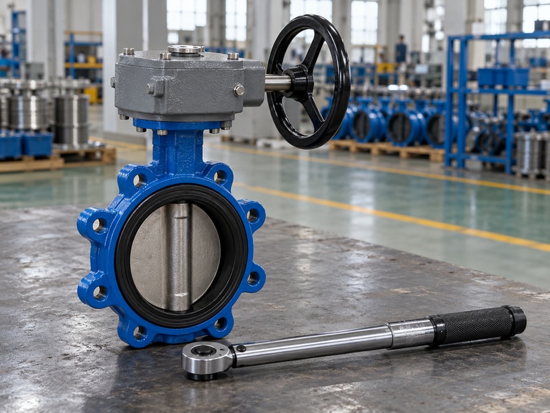
The torque selection for geared butterfly valves should cover the required operating conditions while respecting the shaft, coupling, gearbox and mount limits. Use duty-specific torque information. Maximum closing differential pressure, seat design and service conditions belong in that review; valve diameter and body pressure rating alone do not determine operating effort.
How should manual effort be accepted?
Compare the approved input requirement with the selected wheel radius and the permitted manual operating condition. Record whether the workshop check is unloaded or performed under a specified load. An easy dry stroke cannot replace evidence of operation at the required duty, while excessive input force should not be used to overcome an unexplained obstruction. Keep the agreed sizing allowances visible and verify that the final operating instructions respect the limiting component in the assembly.
- Use duty-specific required torque.
- Compare every torque-carrying component limit.
- Identify conditions behind manual-effort checks.
Key takeaway: Approve sufficient operating torque without allowing an unreviewed overload of the valve or drive.
| Check | What to confirm |
|---|---|
| Required torque | Service conditions and agreed sizing basis. |
| Permitted input | Wheel effort or drive setting within assembly limits. |
5. Which materials suit the process medium?
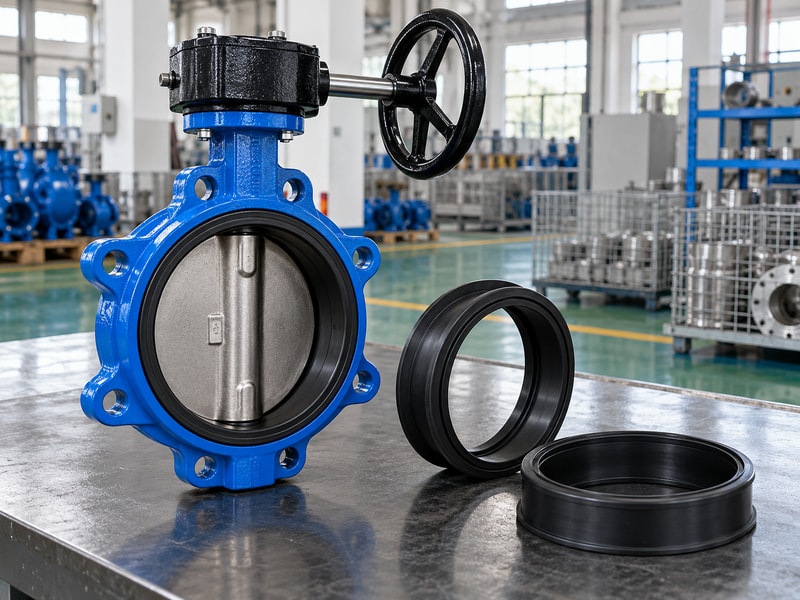
Materials in geared butterfly valves must suit the actual medium, temperature and complete configuration. Elastomer names and metal grades need their specified application boundaries. RUITO specifies water-service EPDM, oil-service NBR and separate lined configurations rather than treating every seat as interchangeable across fluids.
Which material statements need evidence?
Identify the seat, disc, shaft and other wetted materials on the approved bill of materials. For glycol mixtures, include concentration and additives; for chemical duties, provide the full composition and cleaning conditions. Keep drinking-water or fire-service approvals tied to the exact model and market where they are required. A gearbox’s housing or coating choice concerns its ambient exposure and does not establish compatibility of the parts in contact with the process fluid.
- Check the complete wetted-material list.
- State fluid composition and temperature together.
- Verify application-specific approvals for the exact configuration.
Key takeaway: Approve materials against the full service description rather than a seat name alone.
| Check | What to confirm |
|---|---|
| Process materials | Seat, disc, shaft and other wetted parts. |
| Drive materials | Housing, coating, seals and ambient exposure. |
6. How should you check flange and disc clearance?
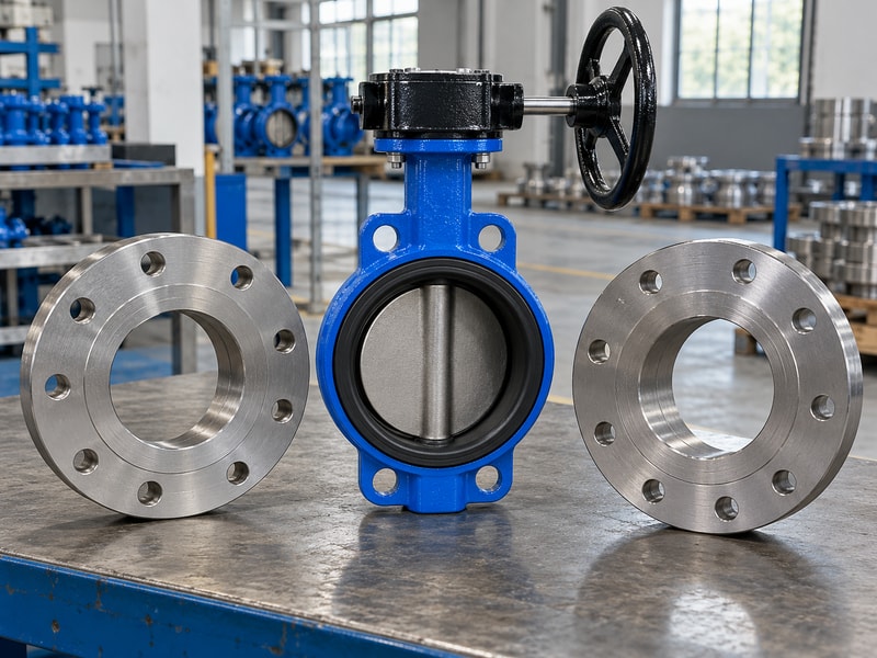
Installation clearance for geared butterfly valves must allow the disc to complete its permitted travel without striking mating flanges or pipework. Wafer and lug arrangements need checks against the actual flange bore and assembly dimensions. Confirm the valve instructions for face sealing and bolting before adding gaskets or tightening the connection.
What should be verified before the line is closed?
Compare the mating flange dimensions and pipe bore with the disc envelope shown in the approved drawing. Check centering, face condition, bolt arrangement and any required gasket treatment for the exact design. A lined valve may have different face requirements from an ordinary resilient-seated valve. Verify clearance before loaded operation, and keep the handwheel and gearbox clear of neighboring supports so the installation does not introduce an unintended load into the valve neck or bracket.
- Check actual flange and pipe bore dimensions.
- Verify disc clearance across the required travel.
- Follow design-specific face-sealing and bolting instructions.
Key takeaway: Confirm both process-side clearance and operator-side access before commissioning.
| Check | What to confirm |
|---|---|
| Bore clearance | Disc envelope against flanges and pipework. |
| External clearance | Gearbox, wheel, supports and maintenance space. |
7. What should the mechanical inspection prove?
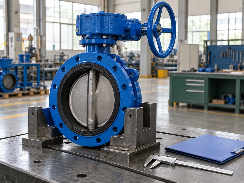
Mechanical inspection of geared butterfly valves should prove that the supplied parts fit, remain aligned and permit the required physical travel. Check the assembly before pressure testing. Gearbox mounting, coupling engagement, fasteners, indication and travel stops each need an acceptance basis that corresponds to the approved configuration.
Which observations belong in the inspection record?
Record the equipment identity and revisions, then check mounting faces, shaft connection and fasteners against the drawing. Confirm the disc position at each endpoint and compare it with the indicator. Note complete-stroke turns and any abnormal resistance using the agreed operating method. If adjustment is needed, follow the valve and gearbox instructions and retain the final settings; do not treat an altered pointer as evidence that the disc reached the correct position.
- Inspect mounting and coupling details.
- Compare indication with physical disc position.
- Record travel, turns and final stop settings.
Key takeaway: Establish a traceable mechanical acceptance record before moving to performance tests.
| Check | What to confirm |
|---|---|
| Assembly checks | Alignment, engagement, fasteners and support. |
| Travel checks | Disc positions, indication, turns and stop settings. |
8. How should geared butterfly valves be tested?
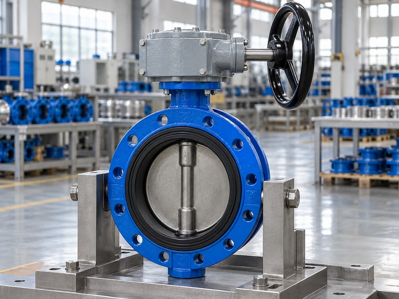
Geared butterfly valves should be tested under the agreed operating, shell-pressure and closure-leakage procedures, with each result recorded separately. Test pressure is not allowable working pressure. Use the exact configuration’s approved medium, direction, temperature, pressure, duration and acceptance criterion rather than applying one test value to every valve in a product family.
How do the pressure records stay unambiguous?
For applicable RUITO PN16 soft-seated configurations, the cold test inputs include 24 bar for the shell and 17.6 bar for closure under the approved procedure. Those figures do not authorize operation at the test pressures or override a model’s directional seat limit. Confirm the selected procedure before testing, including any separate reverse-direction or gas-tightness requirement. Keep operating-torque checks distinct from leakage results, and investigate a failed test instead of compensating with unapproved extra handwheel force.
- Approve the procedure for the exact valve.
- Record shell and closure results separately.
- Distinguish test inputs from working limits.
Key takeaway: Accept pressure and leakage results only against the approved configuration and test procedure.
| Check | What to confirm |
|---|---|
| Applicable PN16 shell input | 24 bar, where required by the approved configuration. |
| Applicable PN16 soft-seat closure input | 17.6 bar, subject to the approved configuration and procedure. |
9. What maintenance should the owner receive?
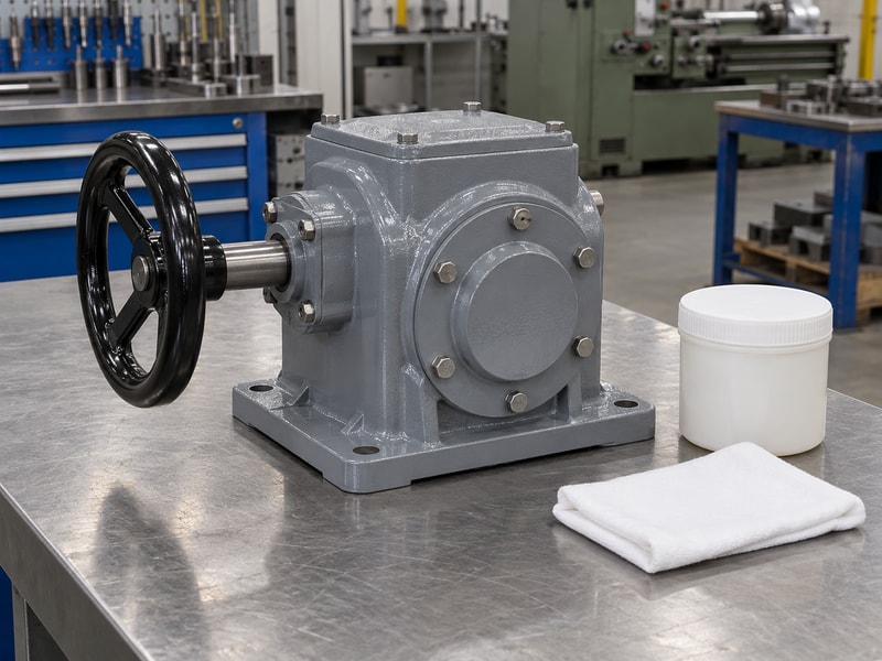
Maintenance instructions for geared butterfly valves should cover the valve, gearbox, mounting and installed operating arrangement. The owner needs the exact lubricant and inspection requirements where applicable, along with the approved limits and settings. A generic maintenance statement leaves uncertainty when the handwheel effort, indication or sealing condition changes later.
What should the owner be able to check?
Provide equipment identification, drawings, parts information and the relevant installation, operation and maintenance instructions. Identify routine external checks and the isolation requirements before adjustment or dismantling. Retain baseline stroke turns, settings and any specified effort measurements under their recorded conditions. Explain which service tasks require supplier review, including matched gear parts, changed mounting arrangements or process-material substitutions, so the maintenance team can distinguish routine inspection from a configuration change.
- Supply model-specific valve and gearbox instructions.
- Retain settings and functional baselines.
- Identify service tasks that need technical review.
Key takeaway: Hand over instructions and records for the exact supplied assembly.
| Check | What to confirm |
|---|---|
| Routine ownership | Identification, inspections and operating instructions. |
| Controlled changes | Parts, materials, interfaces and operating limits. |
10. What should be accepted before shipment?
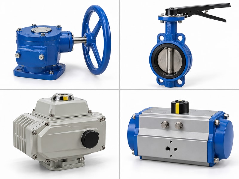
Shipment acceptance for geared butterfly valves should confirm the approved configuration, completed tests and protection of the equipment during transport. RUITO can review the valve duty, operator arrangement and requested documentation before release. Resolve missing records or technical deviations while the assembly remains available for inspection.
Which items should be checked before packing?
Match identification with the approved drawing, bill of materials and test records. Confirm supplied accessories, wheel orientation and any loose parts that need separate protection or installation instructions. Protect sealing faces, the disc area and the drive connections using the approved packing method. Retain photographs and the supplied document index with the equipment record, so the receiving team can check the package against a defined list instead of reconstructing the order after delivery.
- Match equipment identity with approved documents.
- Confirm tests, accessories and remaining deviations.
- Protect valve faces and drive components for transport.
Key takeaway: Release a complete, identified package with its acceptance records and receiving information.
| Check | What to confirm |
|---|---|
| Technical release | Configuration, inspections and completed tests. |
| Delivery release | Accessories, protection, documents and identification. |
Send the valve duty, operator arrangement and acceptance requirements when you contact us. RUITO can review the configuration and the drawings and records needed before shipment.
Frequently asked questions
Q1. Does easy handwheel movement prove that a geared valve is suitable?
No. Check the required torque duty, physical travel, limits and separate pressure and leakage acceptance.
Q2. Can I use pressure-test values as working-pressure ratings?
No. Test conditions and allowable working conditions have different purposes and must remain separately identified.
Q3. How do I know whether the disc will clear the pipework?
Compare the actual mating bore and flange dimensions with the approved disc-travel envelope before operation.
Q4. Can I use the same gasket arrangement for every butterfly valve?
No. Follow the face-sealing and bolting instructions for the exact valve construction.
Q5. What should I receive with the shipment?
Receive the identified assembly, approved drawings, relevant instructions, agreed test records and a clear accessories and packing list.