
Fit a valve gear operator by verifying the valve topworks, output connection, reaction support and full operating envelope before assembly. A matching bolt circle does not prove the package fits. Measure the shaft and registers, approve the coupling engagement and confirm that the handwheel remains usable at the installed location.
Images are AI-generated illustrations of generic equipment configurations.
1. What must a valve gear operator fit?
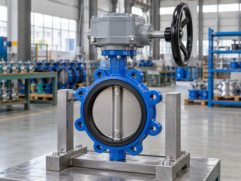
A valve gear operator must fit both the valve’s mechanical interfaces and the installation space in which it will operate. The connection must transmit the specified torque, maintain alignment and carry reaction loads. Confirm the shaft, flange, coupling, bracket and operating envelope as one assembly before ordering a retrofit package.
Why does a bolt-circle match leave questions unanswered?
The output bore may differ from the stem form, a register may hold the mounting faces apart or the coupling may engage too little of the shaft. A bracket can also place the gearbox at an unsuitable height or flex under load. These problems can remain hidden until the valve moves against process resistance. Review a dimensioned assembly drawing and the required load capacity together rather than accepting a photograph showing four bolts in apparently corresponding positions.
- Check every mating feature, not only bolt positions.
- Identify the torque reaction path.
- Review access and maintenance space.
Key takeaway: Approve geometric fit, load transfer and operating access on the same assembly drawing.
| Check | What to confirm |
|---|---|
| Mechanical interface | Shaft, coupling, flange and support. |
| Installed envelope | Handwheel, neighboring equipment and service access. |
2. How do you record the existing topworks?
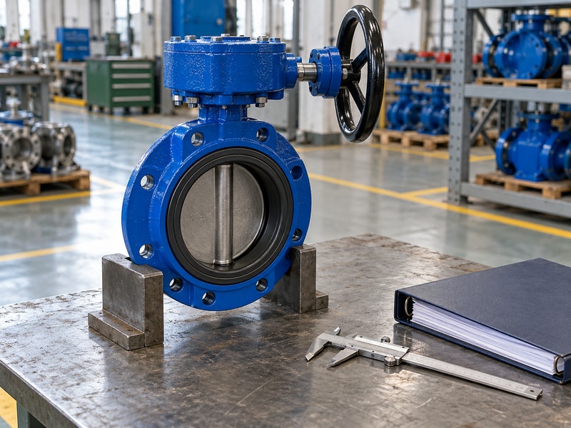
Before fitting a valve gear operator, record the existing valve identity, topworks dimensions and operating conditions. Use current drawings where available and verify measurements on the actual assembly. A retrofit should not silently change the valve’s torque requirement, shaft loading or permitted seating method.
Which evidence should be collected at site?
Photograph the assembly from several useful angles and record readable markings before parts are separated. Measure the mounting features, stem projection and available clearance, then identify which dimensions came from a drawing and which were measured. Note any damage, corrosion, loose fasteners or previous adapter work. If the existing operator became difficult to turn, investigate that condition as part of the survey rather than assuming a new gearbox of the same size will resolve it.
- Record valve and gearbox identification.
- Separate measured dimensions from drawing values.
- Describe condition and the reason for the retrofit.
Key takeaway: Give the designer an equipment survey that explains both the geometry and the operating problem.
| Check | What to confirm |
|---|---|
| Identity record | Valve, operator, markings and revisions. |
| Condition record | Damage, alterations and operating symptoms. |
3. Which valve gear operator flange dimensions need checking?
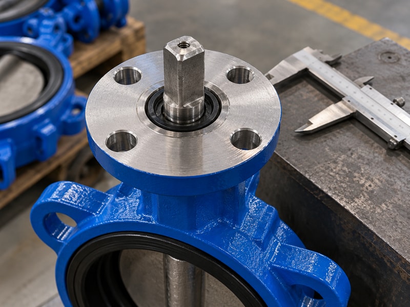
A valve gear operator flange must match the actual hole pattern, register, mounting-face position and fastener arrangement on the valve or bracket. A standard flange designation helps identify an interface but does not describe every shaft and coupling detail. Check both mating drawings and the approved load capacity.
What should the dimensional check show?
Record bolt count, pitch-circle dimensions, hole or thread size, thread form and usable engagement. Include the pilot diameter and depth where a register is used, plus the position of the face relative to the shaft shoulder. Distinguish through holes from threaded holes. A bolt that appears long enough outside the assembly can bottom in a blind hole before clamping the faces, so the fastener review needs the complete stack of parts and the available thread depth.
- Identify holes, threads and usable engagement.
- Check pilot or register dimensions.
- Review fastener length against the complete stack.
Key takeaway: Verify the actual flange features and fasteners rather than relying on the flange name alone.
| Check | What to confirm |
|---|---|
| Positioning features | Pattern, register and mounting-face location. |
| Clamping features | Thread form, fastener length and engagement. |
4. Which valve gear operator shaft features must agree?
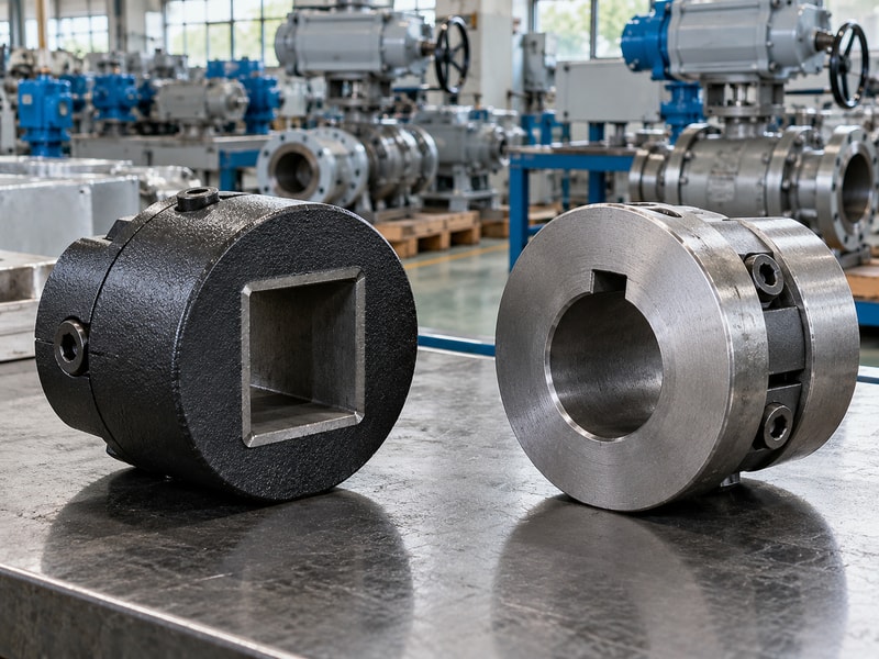
A valve gear operator output must agree with the valve shaft’s shape, dimensions, angular orientation and engagement length. Square, keyed-round and other drive forms need their own matching connection. A coupling that can be pushed onto a shaft may still have an unacceptable fit or insufficient torque-carrying engagement.
How do you check engagement without guessing?
Show the shaft projection, bore depth, shoulders and required end clearance on a sectioned assembly drawing. Confirm whether a key is supplied and how the coupling is retained. Coating, corrosion or a local burr can affect the apparent fit, so identify the intended machined surfaces and inspection method. Do not use mounting bolts to pull a tight or misaligned coupling into place; resolve the dimension or orientation problem before the assembly is tightened.
- Confirm shaft and bore form explicitly.
- Show engagement and end clearance.
- Specify retention, key and inspection details.
Key takeaway: Approve the shaft connection as a dimensioned torque-carrying interface.
| Check | What to confirm |
|---|---|
| Drive geometry | Shape, dimensions and angular orientation. |
| Axial fit | Projection, bore depth, clearance and retention. |
5. How should the mounting bracket carry load?
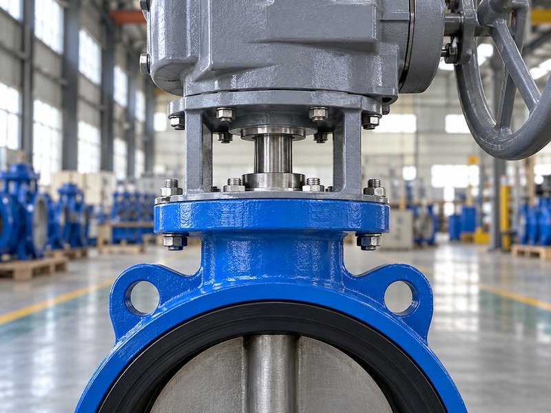
The bracket beneath a valve gear operator must carry reaction torque while maintaining alignment between the output and the valve stem. Its stiffness, mounting faces and fasteners belong in the load review. A taller bracket or a longer coupling can change the behavior of an otherwise suitable gearbox arrangement.
Which layout choices need engineering review?
Check the distance between mounting faces, the support around the coupling and the loads transferred into the valve topworks. Allow access for tightening and inspection without leaving a moving connection exposed where guarding is required. A bracket should locate the parts without forcing the shaft sideways. If a retrofit needs a different bracket height, review the complete connection and installed envelope instead of modifying the original support solely to clear an obstruction.
- Review bracket stiffness and reaction loads.
- Keep shaft alignment through the connection.
- Provide suitable access and guarding provisions.
Key takeaway: Treat a custom bracket as part of the loaded drive package, with its own approved drawing.
| Check | What to confirm |
|---|---|
| Structural duty | Reaction torque and permitted deflection. |
| Assembly duty | Alignment, access and connection support. |
6. What clearance does the handwheel need?
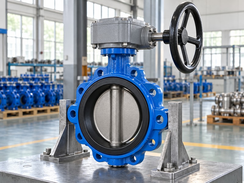
A valve gear operator handwheel needs clearance for its full rotation and enough room for the person operating it. Check wheel diameter, rim position, reach and nearby obstructions. An arrangement that fits a shipping envelope may still be impractical once insulation, pipe supports or adjacent equipment are installed.
How should you assess the operating position?
Show the handwheel envelope on the plant layout and confirm where the operator can stand. Include the space occupied by guards, cables and maintenance tools where relevant. Review input effort and the number of turns, since a position tolerable for a brief movement may be unsuitable for repeated full strokes. If the wheel must move to another side, confirm the manufacturer’s permitted mounting orientation and indication arrangement before rotating or modifying the gearbox.
- Check the complete rotating wheel envelope.
- Confirm reach from a usable operating position.
- Review permitted orientation and indication.
Key takeaway: Verify the final operating position on the installed layout, including neighboring equipment.
| Check | What to confirm |
|---|---|
| Static clearance | Housing, bracket and adjacent structures. |
| Operating clearance | Wheel rotation, reach and maintenance access. |
7. How do you set travel stops?
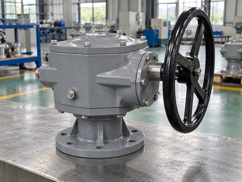
Travel stops on a valve gear operator should be set to the valve manufacturer’s seating and travel instructions after the coupling orientation is confirmed. Stop settings must allow the required open and closed positions without applying unapproved excess torque. Keep mechanical stop adjustment separate from pressure and leakage acceptance.
What should be checked during adjustment?
Confirm the physical disc position and required clearance before using an indicator as the reference. Move the assembly using the approved procedure and check whether the stop or the valve seating condition governs the endpoint. Record the final settings and direction of operation. If the valve does not meet its leakage criterion, investigate the valve and test conditions instead of moving the stop farther or increasing input force without authorization from the responsible technical team.
- Confirm physical position and coupling orientation.
- Use the valve’s required seating procedure.
- Record travel, indication and final settings.
Key takeaway: Set stops from the valve instructions and verify performance through the separate agreed test.
| Check | What to confirm |
|---|---|
| Adjustment basis | Required travel and seating method. |
| Acceptance basis | Recorded function and specified leakage test. |
8. What changes with an extension or chainwheel?
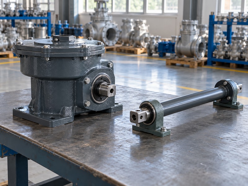
An extension or chainwheel for a valve gear operator changes how input effort reaches the gearbox and how the assembly is supported. Specify reach, orientation, connection and maintenance access as a complete arrangement. A long unsupported shaft or an improvised chainwheel can introduce loads and operating conditions that the original package did not cover.
Which details should appear in the enquiry?
Provide installed height, operating position and the route available for an extension or hanging chain. Ask the supplier to identify required supports, couplings, guards and retention details. Check the permitted input torque at the new operating connection and whether the direction of operation remains clear. Also consider how the equipment will be isolated and inspected later, since an arrangement that can be operated from below still needs a workable maintenance method at the gearbox.
- State the complete route and operating position.
- Include supports, connections and retention.
- Check input limits and later inspection access.
Key takeaway: Order remote manual input arrangements as reviewed assemblies rather than loose accessory parts.
| Check | What to confirm |
|---|---|
| Extension arrangement | Length, support, alignment and couplings. |
| Chainwheel arrangement | Reach, retention, route and operating access. |
9. How should you accept the retrofit?
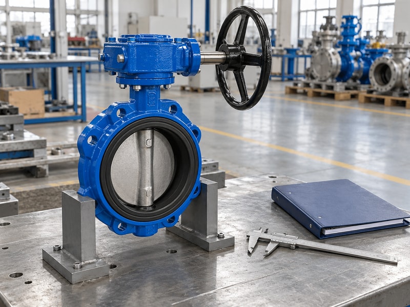
A valve gear operator retrofit should be accepted through dimensional, functional and duty-related checks on the complete assembly. A successful dry bench stroke confirms only part of the requirement. Agree how the supplied mounting kit, indication and operating effort will be verified, and how the valve’s pressure and leakage tests will be handled.
What should the acceptance record identify?
Record the valve and gearbox identities, drawing revisions, coupling and bracket details, fastener checks and final travel settings. Confirm handwheel direction, turns and indication against physical travel. Where loaded operation is part of the acceptance scope, state the conditions and limits rather than substituting an unloaded observation. Retain any deviations and their approvals with the record, so the equipment owner knows exactly what was tested and which conditions remain to be confirmed during commissioning.
- Identify all supplied parts and approved revisions.
- Record fit, travel, effort and indication checks.
- Separate workshop and site acceptance conditions.
Key takeaway: Accept the retrofit against a defined test scope with traceable results.
| Check | What to confirm |
|---|---|
| Workshop checks | Dimensions, assembly and agreed functional tests. |
| Site checks | Installed clearance and specified operating conditions. |
10. Which drawings should you approve before shipment?
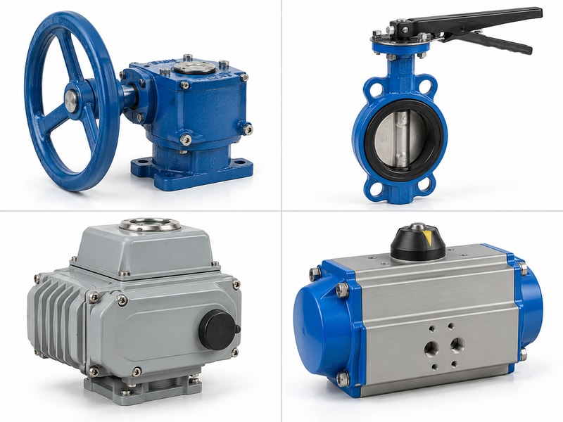
Approve the valve gear operator assembly drawing, interface details and acceptance plan before the replacement is manufactured or shipped. RUITO can review the valve duty and topworks information for a requested drive package. Resolve measured discrepancies before release rather than leaving site personnel to decide which part should be modified.
What should the final drawing package include?
Include overall dimensions, wheel orientation, shaft and coupling details, bracket dimensions, fasteners and the required travel relationship. Add the supplied parts list and operating limits, with inspection and test documents tied to the equipment identity. For future replacements, retain the approved revision and the as-supplied record. If a later order changes an interface, material or gearbox arrangement, review that change against the original valve duty and installed layout before accepting it.
- Approve overall and detailed interface drawings.
- Retain as-supplied identification and test records.
- Control later changes to fit or operating limits.
Key takeaway: Release the retrofit only when the drawing and test package describe the assembly that will arrive.
| Check | What to confirm |
|---|---|
| Before manufacture | Resolve duty, dimensions and technical deviations. |
| Before shipment | Verify the supplied configuration and required records. |
Send the topworks drawing, measured dimensions and installation photographs when you contact us. RUITO can review the valve package and identify the interfaces that need approval before manufacture.
Frequently asked questions
Q1. Can I approve the retrofit from the bolt-circle size?
No. Check registers, shaft form, coupling engagement, fasteners and the reaction support as well.
Q2. Can I rotate the gearbox to move the handwheel?
Only within the manufacturer’s permitted arrangement, with travel and indication checked afterward.
Q3. How do I know whether the coupling is long enough?
Compare the required engagement and end clearance on a sectioned assembly drawing.
Q4. Can I adjust the stop until seat leakage disappears?
Use the specified seating and adjustment procedure. Investigate leakage through the agreed valve test rather than adding unapproved travel or force.
Q5. Which document is most useful for repeat supply?
Keep the approved as-supplied assembly drawing, parts list, equipment identity and interface revisions.