
Fix pneumatic butterfly valve sizing mistakes by matching available actuator output with valve torque across the complete stroke at minimum delivered air pressure. A heavy duty pneumatic actuator for butterfly valves can move freely on a bench yet stall against the real closure differential. Define fail action, mounting and control requirements alongside torque so RUITO can review the complete assembly before you order.
Images are AI-generated illustrations of configurations and review tasks.
1. What is a heavy duty pneumatic actuator for butterfly valves?
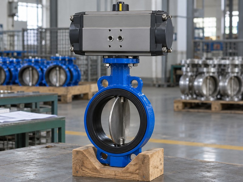
A heavy duty pneumatic actuator for butterfly valves converts compressed-air energy into the rotary output needed by the valve assembly. Rack-and-pinion and scotch-yoke mechanisms have different output characteristics. Heavy duty does not identify a universal torque range, allowable cycle count or environmental rating, so request the exact actuator data for your application.
Match the mechanism to the operating duty
Begin with the valve duty rather than the actuator’s appearance. A large housing can still provide insufficient output at the lowest pressure available during operation. The required quarter-turn travel, movement frequency and ambient exposure also belong in the selection. Confirm which valve, coupling, bracket and accessories the supplier includes so the engineering review covers the complete load path from actuator output to valve shaft.
- Identify the actual valve construction and required movement.
- State operating frequency and ambient installation conditions.
- List the actuator, coupling, bracket and controls in scope.
| Check | Required evidence |
|---|---|
| Valve duty | Function, travel and operating frequency |
| Actuator data | Mechanism and output under stated conditions |
Request a selection tied to the complete assembly and duty.
2. How do you compare valve and actuator torque?

Size a heavy duty pneumatic actuator for butterfly valves by comparing the available actuator output with valve breakaway, running and seating demand throughout the stroke. Use the minimum pressure delivered at the actuator during movement. A compressor setting or a static gauge reading upstream cannot establish the pressure available through the actual supply arrangement.
Check output throughout both required movements
Ask for the valve torque conditions, including maximum closure differential, medium, temperature and seat material. Compare those requirements with the actuator curve and the supplier’s justified selection margin. For a spring-return unit, check the air stroke and spring stroke separately. Also verify maximum output against shaft, coupling and valve limits; more torque can damage an assembly whose permitted loading has been overlooked.
- Obtain valve demand and actuator output on comparable conditions.
- Account for pressure losses during the required movement.
- Document the selected margin and maximum allowable assembly loads.
| Check | Required evidence |
|---|---|
| Demand | Breakaway, running and seating torque |
| Supply | Minimum delivered pressure and output profile |
Keep the torque comparison with the approved actuator selection.
3. Which fail action does your process require?
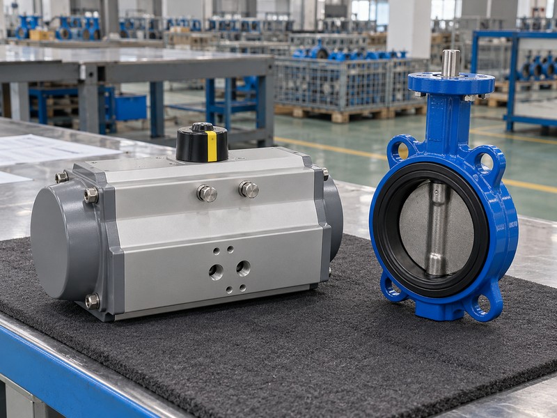
Choose a heavy duty pneumatic actuator for butterfly valves fail arrangement from the process risk and the complete pneumatic circuit. A spring-return actuator can drive toward its configured end position when air is released, provided its output overcomes the required load. The accepted safe position must come from the system design rather than a general product label.
Define each loss-of-supply response
Specify the required response to loss of air, electrical power and command signal separately. A double-acting actuator has no inherent spring-driven return, and its position after supply loss depends on the circuit, trapped air and process forces. A spring-return package also needs the correct solenoid exhaust arrangement and adequate return torque. Confirm the intended state with the responsible system engineer before selecting accessories or promising a fail response.
- State required positions for air, power and signal loss.
- Check spring output over the full return movement.
- Review the solenoid arrangement and complete pneumatic circuit.
| Check | Required evidence |
|---|---|
| Process decision | Required safe position for each failure |
| Assembly evidence | Torque and circuit support for that response |
Approve failure behaviour before freezing the actuator and controls.
4. How should mounting and coupling be checked?
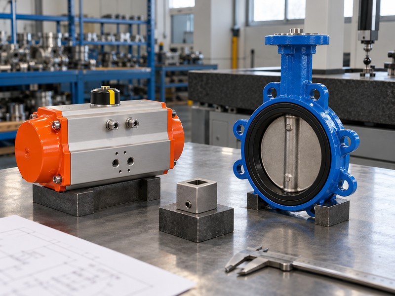
Mount a heavy duty pneumatic actuator for butterfly valves only after checking the drive shape, effective engagement, mounting dimensions and allowable loads. An ISO 5211 interface designation can help identify a mounting arrangement, but the actual valve shaft, coupling and bracket still need dimensional confirmation. Check the complete assembly drawing before substituting an actuator.
Verify dimensions and the mechanical load path
During replacement work, measure the installed envelope as well as the bolt pattern. Coupling depth, shaft height and bracket stiffness affect engagement and alignment. An actuator that fits the mounting holes may still bottom out on a shaft or leave insufficient drive contact. Include mounting orientation, access and external support in the review so the valve shaft does not carry unintended bending loads from the surrounding installation.
- Confirm drive shape, shaft height and effective coupling engagement.
- Review fastener specification and the bracket load capacity.
- Check the installed envelope and maintenance access.
| Check | Required evidence |
|---|---|
| Interface | Approved dimensions and coupling details |
| Loads | Permitted torque, support and mounting arrangement |
Treat dimensional fit and mechanical load approval as separate checks.
5. How do the medium and seat affect selection?
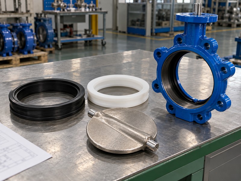
Review a heavy duty pneumatic actuator for butterfly valves together with the valve’s actual medium and seat configuration because those conditions affect required torque and permitted service. Compressed air powers the actuator; it does not give the process valve approval for gas service. Each valve construction still needs its own working limits and material review.
Keep process duty and drive-air conditions distinct
For example, RUITO separates EPDM water duty, NBR mineral-oil duty and lined chemical-liquid configurations. Its PTFE and PFA options have their own size, temperature, pressure and medium boundaries. A deposit-forming liquid or a cleaning cycle can change seat friction, so provide those exposures before the supplier calculates torque. Request an accepted valve-and-drive selection whenever the material package or operating temperature changes.
- Provide the complete medium, cleaning liquid and operating temperatures.
- Use torque data for the actual seat and valve construction.
- Keep process pressure and actuator air pressure separately identified.
| Check | Required evidence |
|---|---|
| Process side | Materials and pressure-temperature limits |
| Drive side | Air quality, delivered pressure and output |
Recheck the selection after a change to medium or seat material.
6. Which controls belong in the supply scope?
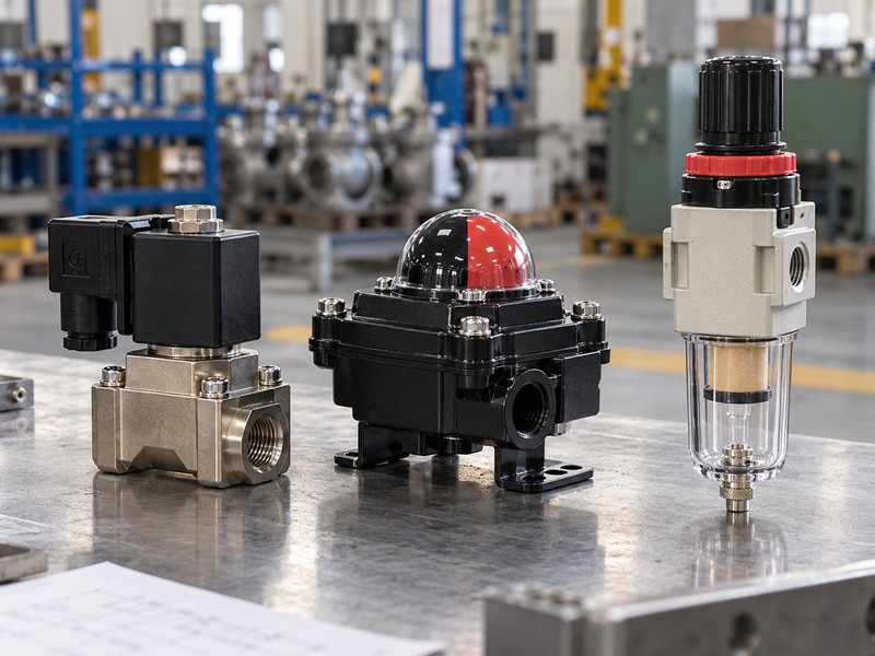
Equip a heavy duty pneumatic actuator for butterfly valves with controls that match the required on-off or modulating duty. A solenoid routes air, a position switch reports a defined state, and a positioner controls actuator position from its configured command. Their functions and ratings should appear individually in the assembly specification.
Specify signals, ratings and accessory functions
For an on-off package, identify the electrical supply, solenoid arrangement, feedback contacts and required failure response. For modulating service, state the command and feedback signals, intended operating range and valve control data. Position feedback alone cannot prove the valve meets a process-flow target. Environmental protection and any hazardous-area requirements also apply to the complete installation and the exact accessories being offered.
- List electrical supply, command type and feedback requirements.
- Define the solenoid and position-control functions separately.
- Check enclosure and installation requirements for every included accessory.
| Check | Required evidence |
|---|---|
| Control duty | On-off logic or defined modulation |
| Included scope | Accessory ratings, signals and connection details |
Approve the control diagram alongside the mechanical assembly drawing.
7. How should operating speed be selected?
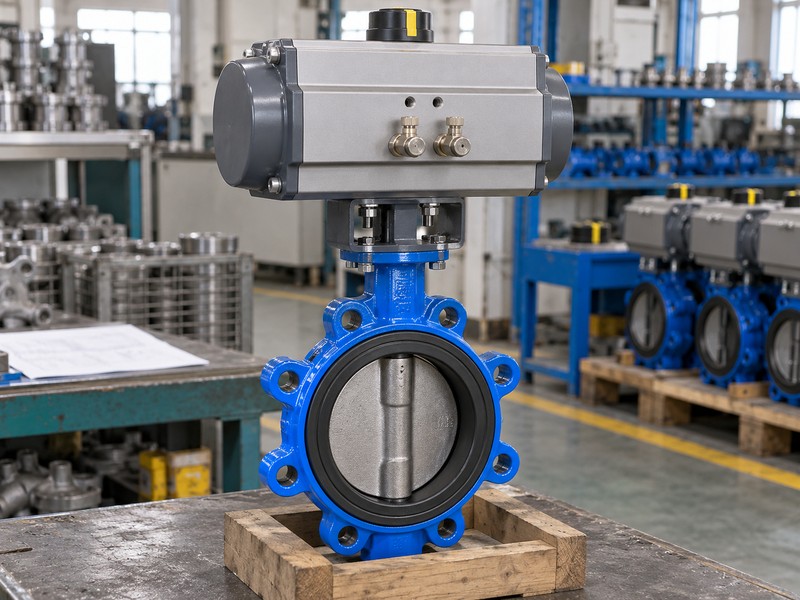
Set a heavy duty pneumatic actuator for butterfly valves operating speed from the system’s allowed response and the actuator’s supply and exhaust arrangement. Fast movement can be unsuitable where closure produces an unacceptable pressure transient. Slow movement can also fail a process requirement, so specify a permitted movement profile before adjusting flow controls.
Review the pipeline response and air path
Review the line conditions, required closure behaviour and actual air-path capacity with the system designer. Tubing length, fittings, regulators, solenoids and exhaust restrictions affect the delivered movement. A recorded unloaded bench time is only evidence for those test conditions. Confirm the accepted operating settings during the agreed assembly or commissioning checks and control later adjustments so a maintenance change does not silently alter system behaviour.
- State acceptable opening and closing behaviour for the system.
- Review supply and exhaust components as a complete air path.
- Record the approved settings and the conditions used for verification.
| Check | Required evidence |
|---|---|
| System requirement | Accepted stroke behaviour and transient review |
| Assembly check | Actual supply, exhaust and control settings |
Document movement requirements instead of assuming faster operation is better.
8. What should the functional acceptance test include?
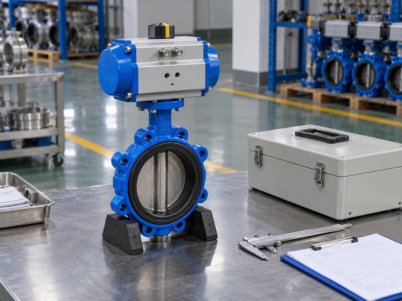
Accept a heavy duty pneumatic actuator for butterfly valves package against a procedure that verifies travel, required failure response, feedback and agreed operating conditions. A valve pressure-test report covers the specified valve test; it does not by itself prove the actuator selection or control logic. Record the exact assembly and accessory revisions used.
Separate pressure integrity from assembly behaviour
Agree which checks belong at the factory and which need site conditions. Confirm endpoints, external movement, indication and the response required by the control diagram. Where minimum-pressure performance is part of acceptance, define the measurement point and test conditions. Keep shell, closure and gas-tightness records separate as applicable, then link them with the functional record through the same product identity so the delivered package remains traceable.
- Define the functional procedure and accepted operating conditions.
- Verify indication and feedback against actual valve travel.
- Close wiring, pneumatic and mechanical deviations before release.
| Check | Required evidence |
|---|---|
| Valve acceptance | Applicable pressure and closure records |
| Assembly acceptance | Travel, response, feedback and configuration |
Release the assembly only after its agreed deviations are closed.
9. What information should accompany the inquiry?
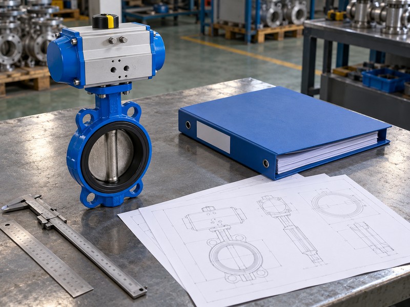
Specify a heavy duty pneumatic actuator for butterfly valves by supplying valve torque data, minimum delivered air pressure, fail action and the installation envelope with your inquiry. Add the medium and maximum closure differential if the valve also needs selection. These inputs let the supplier identify missing assumptions before quoting an assembly.
Make the sizing assumptions visible
Send RUITO the valve drawing, size, connection, seat material and operating temperatures. State the movement frequency, ambient exposure, opening and closing requirements, electrical supply and feedback signals. Include required inspection documents and any destination-specific approval scope. Ask for the selected actuator curve, coupling details, control diagram and declared deviations in the offer so you can review the package before accepting a delivery date.
- Attach the valve torque conditions and minimum air-pressure requirement.
- Define mounting, failure response and control interfaces.
- Request the selection basis and included acceptance documents.
| Check | Required evidence |
|---|---|
| Sizing inputs | Valve demand, air supply and operating duty |
| Review outputs | Assembly drawing, output data and control scope |
Contact us with the valve duty and control requirements for an assembly review.
10. Which questions should you resolve before ordering?
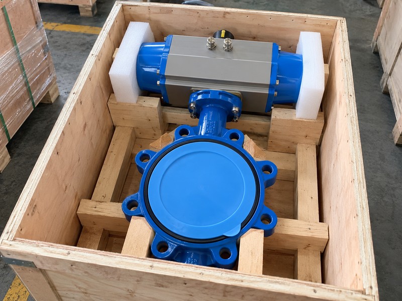
Resolve torque inputs, air-loss response, selection margin, mounting fit and feedback limits before ordering a heavy duty pneumatic actuator for butterfly valves. Keep those answers with the approved assembly record.
Q1. Can I size the actuator from valve diameter alone?
No. Use the exact valve torque profile, closure differential, medium and seat conditions. Compare them with actuator output at minimum delivered air pressure, then check the permitted loads on the complete assembly.
Q2. Does a double-acting unit always hold its last position?
No. Its response after air loss depends on the circuit, trapped air and process forces. Define the required behaviour and verify it with the complete control arrangement.
Q3. What is the best safety margin for actuator torque?
Use the margin justified for the actual valve, actuator and duty. A fixed percentage cannot account for every seat, supply-pressure variation or process condition. Check available output and allowable assembly loads together.
Q4. Can I replace an actuator with the same mounting pattern?
Only after checking the full interface. Drive shape, engagement, shaft height, torque limits and bracket arrangement must also match. Review the replacement assembly drawing before installation.
Q5. How do I know if position feedback proves tight shutoff?
It does not establish leakage performance by itself. Feedback reports its configured state. Verify valve travel and use the agreed closure test to assess shutoff under the specified acceptance conditions.