
Fix triple-offset mechanism mistakes by separating two shaft-position offsets from the inclined conical sealing geometry. The question “how does a triple offset butterfly valve work” needs an actual section drawing, seat definition and drive basis. The disc still rotates; the selected geometry governs how its sealing surfaces approach and release contact.
If an enquiry treats three offsets as three moving joints, the proposed explanation can misidentify both the mechanism and the required actuator. A metal-seat photograph can also look convincing while leaving the geometry unverified. Trace the fixed axes and sealing surfaces on the selected drawing, then separate the operating principle from the performance evidence your project requires.
1. By its geometry, how does a triple offset butterfly valve work?
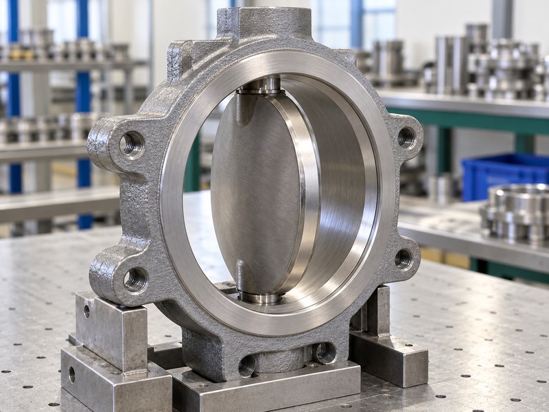
A rotating disc uses two positional offsets and inclined conical sealing geometry to approach and release its seat. Use “how does a triple offset butterfly valve work” as a drawing-review question, with the actual shaft, bore and sealing references identified. The three offsets describe one assembly’s fixed geometry.
What does the section drawing need to identify?
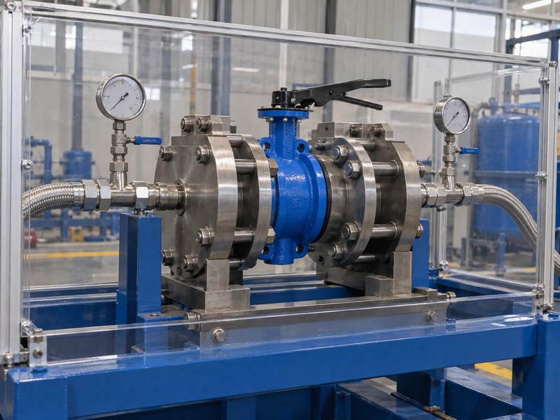
Locate the shaft axis, pipe-bore centreline, seat plane and conical sealing references on one accepted drawing. Compare their relationships. A metal sealing band alone cannot establish those offsets or a specific contact path, so request the geometry and assembly definition behind the picture. The illustration depicts generic metal-seat contact.
- Identify shaft, bore, seat and sealing-geometry references.
- Separate fixed offsets from the disc’s rotary movement.
- Request the actual construction behind a seat photograph.
Key takeaway: Verify the actual geometric relationships and rotary disc motion against the selected drawing.
| Check | What you should confirm |
|---|---|
| Motion | Disc rotates through its accepted shaft travel |
| Geometry | Two positional offsets and inclined sealing references identified |
| Evidence | Actual drawing supports the proposed construction |
2. With two offsets, how does a triple offset butterfly valve work?
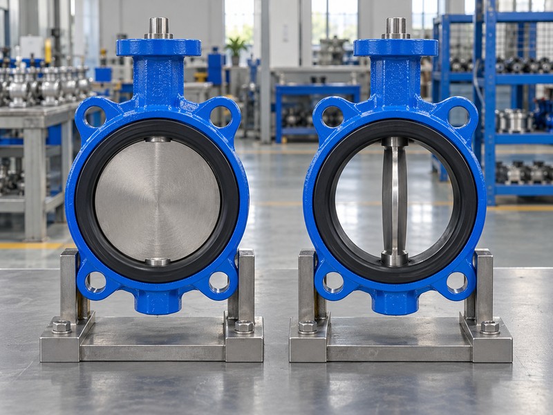
The positional offsets place the shaft away from the seat plane and the bore or disc centreline. In a “how does a triple offset butterfly valve work” review, distinguish those fixed displacements from the additional sealing-cone inclination. They change the disc’s path relative to the seat while the shaft remains the axis about which the disc rotates.
How does a concentric reference help the comparison?
A concentric reference places the shaft and disc in the centred arrangement shown in the comparison image. Follow the actual axes. Offset construction requires its own section drawing because a centred open-and-closed illustration cannot depict either displacement. Use identified drawing datums; offset numbering cannot replace their physical relationships or supply universal dimensions.
- Locate each positional displacement on the actual section.
- Compare centred and offset arrangements without mixing drawings.
- Use identified datums rather than assumed offset dimensions.
Key takeaway: Locate the shaft relative to sealing and bore references, keeping both positional offsets separate from motion.
| Check | What you should confirm |
|---|---|
| Seat-plane relation | Actual shaft displacement is identified |
| Centreline relation | Bore or disc reference is defined |
| Comparison | Concentric illustration remains a separate reference |
3. At the cone, how does a triple offset butterfly valve work?
The additional offset concerns the inclination of the conical sealing geometry, which changes how mating sealing surfaces approach one another. The “how does a triple offset butterfly valve work” drawing review should identify that inclination separately from the shaft-position offsets.
Which sealing references should the reviewer compare?
Ask for the cone axis, sealing surface and relevant section references on the selected design. Compare the mating geometry. The disc seal and body seat must correspond to that definition, including the actual attachment and assembly requirements. A general cone sketch cannot provide a universal cone angle, contact clearance or machining tolerance; those values belong to the accepted construction and its inspection plan.
- Identify cone inclination separately from shaft-position offsets.
- Compare the mating seat and disc-seal definitions.
- Use model-specific dimensions and inspection tolerances.
Key takeaway: Use the actual design for sealing inclination, dimensions and mating-part requirements.
| Check | What you should confirm |
|---|---|
| Inclination | Conical sealing reference and axis are identified |
| Mating parts | Disc seal and seat follow the same definition |
| Dimensions | Actual drawing provides values and tolerances |
4. On opening, how does a triple offset butterfly valve work?
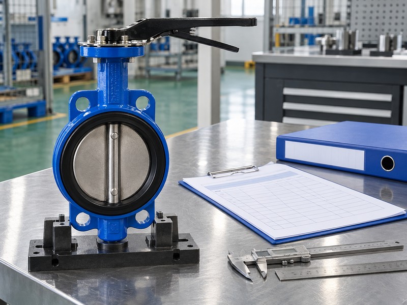
The shaft rotates the disc so the selected offset geometry releases the sealing surfaces as opening proceeds. In the “how does a triple offset butterfly valve work” explanation, follow the contact path alongside the shaft angle. The disc remains connected to its shaft through the accepted rotary envelope.
What should you verify about contact release?
Use the section and assembly information to identify how the selected surfaces disengage. Follow the actual movement. Do not assign a universal disengagement angle or assume every metal seat has the same rubbing behaviour through travel. A physical operating check needs the selected instructions, qualified personnel and authorized isolation, with observed position linked to the drawing and accepted limits.
- Trace the selected surfaces through opening travel.
- Keep contact release separate from a universal angle claim.
- Use authorized procedures for any physical movement check.
Key takeaway: Opening combines disc rotation with the selected geometry’s contact-release path; the actual design determines where and how that contact changes.
| Check | What you should confirm |
|---|---|
| Rotation | Shaft and disc follow the accepted movement envelope |
| Contact | Release behaviour follows the actual geometry |
| Check | Observed motion retains its procedure and product identity |
5. At closure, how does a triple offset butterfly valve work?
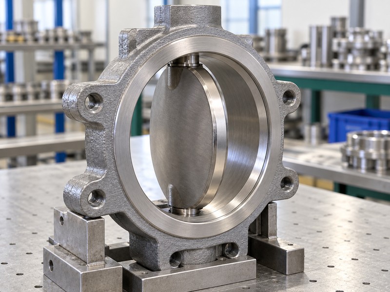
The drive returns the disc to the accepted closed geometry and applies the specified seating conditions to the mating seal. Your “how does a triple offset butterfly valve work” review should distinguish that physical contact from the leakage result. A metal seat or a closed pointer cannot establish zero leakage under every medium, pressure, direction or temperature.
What should the sealing acceptance define?
Identify the actual seat materials, seal attachment, seating requirements and permitted closure differential. Review the acceptance conditions. Keep shell integrity, shaft external leakage and closed-seat leakage as separate checks, with their required method and criterion stated. If a closure result fails, the responsible team should review contact geometry, indexing and the inspection findings before changing force or stop settings.
- Identify the accepted closed geometry and seating conditions.
- Specify medium, direction and leakage acceptance separately.
- Review failed closure before altering force or stops.
Key takeaway: Verify seat contact and the separate inspection evidence for the agreed leakage conditions.
| Check | What you should confirm |
|---|---|
| Position | Disc reaches its accepted closed reference |
| Contact | Seat and seal match the specified assembly |
| Result | Leakage acceptance retains its defined test conditions |
6. Under load, how does a triple offset butterfly valve work?
The operator must supply the torque required by the valve throughout its accepted stroke and seating conditions. Connect the “how does a triple offset butterfly valve work” question with actual fluid loads, closing differential and drive output. Offset geometry cannot establish one universal torque value, and a freely moving unloaded assembly cannot prove operation at the required process load.
Which transmission and supply conditions need review?
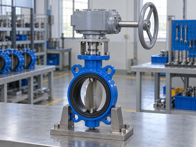
Compare demanded and available torque across travel, including applicable shaft and coupling limits. Trace the complete drive. A gearbox converts handwheel input to rotary output, so the selected gearing determines input turns; a powered drive needs its actual minimum supply and required return conditions. Use the selected manuals for indication and limits, with no universal turning direction or position-holding assumption.
- Use actual duty and closing-differential inputs.
- Compare torque and component loads across travel.
- Separate gearbox input from valve output movement.
Key takeaway: Drive selection needs the actual valve loads and operator conditions across the stroke.
| Check | What you should confirm |
|---|---|
| Demand | Fluid, differential and seating conditions are identified |
| Output | Actual drive conditions cover the required stroke |
| Transmission | Gearing, shaft and coupling fit the assembly |
7. In a pipe, how does a triple offset butterfly valve work?
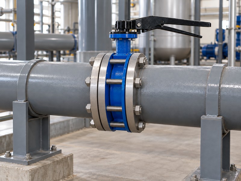
The disc rotates inside an installation that must accommodate its full accepted sweep and the body’s specified connection. In a “how does a triple offset butterfly valve work” installation review, verify the actual flange, pipe bore and moving envelope. Offset geometry does not establish interchangeable face-to-face dimensions, a generic gasket rule or unrestricted end-of-line service.
What should an installation drawing establish?
Compare the selected connection, drilling, facing and face-to-face length with the mating system. Check the moving envelope. Include the disc sweep, shaft and actuator access, pipe supports and any lining or reducer that changes clearance. Record binding for engineering review before changing drive force.
- Match the actual connection and interface dimensions.
- Check full disc sweep against mating pipework.
- Resolve interference before changing drive force or stops.
Key takeaway: Verify actual dimensions and clearances independently of the offset designation.
| Check | What you should confirm |
|---|---|
| Interface | Drawing matches flange and face-to-face requirements |
| Clearance | Disc and operator envelopes fit the installation |
| Support | Joint and pipe loads follow the accepted design |
8. During flow, how does a triple offset butterfly valve work?
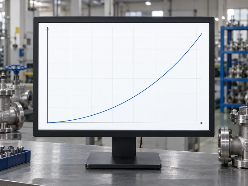
Disc rotation changes the available flow passage while the disc and shaft remain inside the bore. The “how does a triple offset butterfly valve work” review needs actual opening-specific hydraulic data alongside geometry. Travel percentage cannot establish flow percentage, and full opening cannot establish zero pressure loss or automatic suitability for continuous throttling.
What does the conceptual curve leave unresolved?
The illustration fixes liquid density and flow coefficient while pressure loss increases with flow. Review the actual sizing basis. Model size, opening, fluid properties and pressure conditions determine the relevant calculation and operating envelope, including required cavitation or noise assessment. Gas sizing uses its own inputs, and a fixed-coefficient liquid curve cannot become a measured result for every opening or construction.
- Separate mechanical travel from measured process flow.
- Request opening-specific coefficient and operating-envelope data.
- Review actual fluid and system pressure conditions.
Key takeaway: Hydraulic suitability needs selected valve and system data, with the control range reviewed separately.
| Check | What you should confirm |
|---|---|
| Travel | Disc position identifies a mechanical opening |
| Data | Coefficient matches the actual model and opening |
| Duty | System conditions support the proposed flow function |
9. In service, how does a triple offset butterfly valve work?
The same rotary principle operates within the selected materials, pressure-temperature rating and permitted directional closure limits. Use “how does a triple offset butterfly valve work” to investigate those boundaries rather than infer them from a construction label. General triple-offset geometry cannot establish a particular temperature range, equal reverse-pressure performance or approval for a specialized application.
What scope can the available product evidence support?
Request the actual materials, operating envelope and direction-specific ratings for the proposed product. Verify the documented supply scope. RUITO’s documented range covers concentric and double-offset butterfly configurations; it does not confirm a triple-offset offering. Any triple-offset procurement requirement needs separate availability confirmation and product evidence, without transferring another valve family’s working conditions, approvals or inspection results.
- Verify materials and the actual pressure-temperature envelope.
- Identify closure ratings for each required pressure direction.
- Confirm product availability separately from general mechanism education.
Key takeaway: Confirm the actual product, ratings and supply scope before procurement approval.
| Check | What you should confirm |
|---|---|
| Service | Actual material and operating limits support the duty |
| Direction | Each required closure differential is declared |
| Supply | Proposed construction has separately confirmed availability |
10. At acceptance, how does a triple offset butterfly valve work?
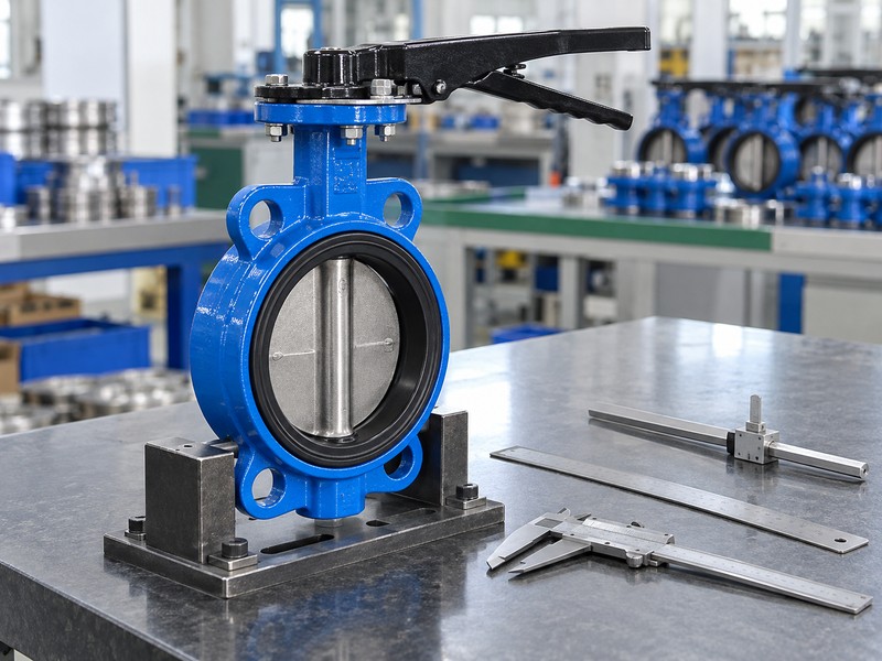
Acceptance connects the identified valve’s geometry and observed movement with its required inspection results. Close the “how does a triple offset butterfly valve work” review with the actual drawings, material definition and operating records. A generic illustration or successful rotation cannot establish pressure integrity, leakage acceptance or every required product approval for the supplied configuration.
Which records establish the accepted result?
Match product identity with dimensions, functional observations and the agreed pressure-test records. Review each inspection scope. A method such as ISO 5208 addresses its specified pressure-testing conditions and cannot establish control precision or a universal leakage promise. Required approvals must cover the actual model, materials, sizes and destination, while a management certificate retains its separate organizational scope.
- Connect drawings and results with the actual product.
- Separate movement, pressure and approval evidence.
- Retain conditions, findings and authorized acceptance decisions.
Key takeaway: A traceable acceptance package states which construction was supplied and what that identified valve demonstrated under the agreed conditions.
| Check | What you should confirm |
|---|---|
| Geometry | Accepted drawing identifies the supplied construction |
| Inspection | Required results state conditions and product identity |
| Approval | Exact product and destination coverage are verified |
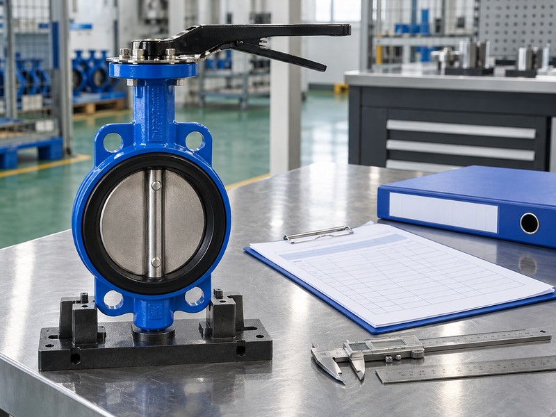
Send RUITO your required construction, service sheet, installation drawing and inspection scope. We can review the enquiry and clarify which configurations have confirmed supply information and which need further verification. Contact us before treating a general mechanism explanation as a product offer or acceptance result.
FAQ
Q1: Can I count three offsets from a metal-seat photo?
No. Use the actual section drawing to identify the two positional offsets and inclined conical sealing geometry.
Q2: What’s the difference between an offset and another moving joint?
An offset is a geometric relationship. The disc still rotates about its shaft through the accepted operating stroke.
Q3: Can I assume every triple-offset valve has zero leakage?
No. Verify the actual sealing construction and agreed leakage criterion under the specified medium, pressure, direction and temperature conditions.
Q4: How do I know if the same actuator can operate another size?
Review its sizing basis. Compare actual valve demand and available output across travel, including shaft, coupling and supply conditions.
Q5: Does this explanation confirm a RUITO triple-offset product?
No. RUITO documents concentric and double-offset configurations; a triple-offset requirement needs separate availability and product evidence.