
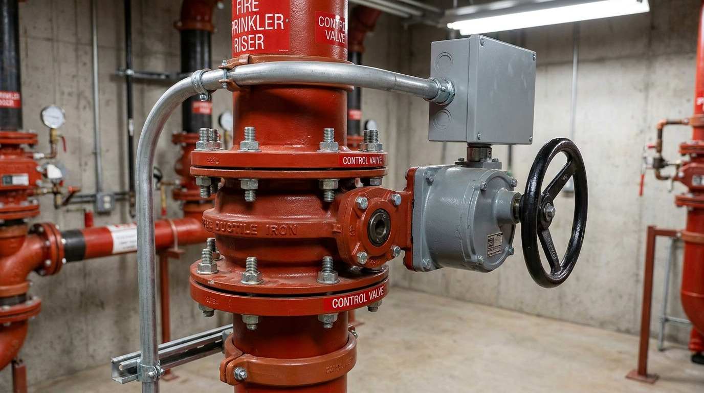
A butterfly valve with a tamper switch is a specialized quarter-turn flow control valve equipped with an integrated electrical supervisory switch that triggers an alarm if the valve disc is moved from its fully open position. In commercial fire protection, a closed water control valve during routine maintenance can lead to catastrophic system failures when an emergency occurs. Think about the severe liability of failing local fire inspections, or worse, suffering massive building damage because water couldn’t reach the sprinklers. Our butterfly valve with tamper switch offers the ultimate solution, combining space-saving flow control with automated electrical monitoring to guarantee your system is always ready.
Why use a butterfly valve with tamper switch?
You install a butterfly valve with tamper switch to ensure that your fire protection water supplies cannot be closed without triggering an immediate alarm. This safety setup protects high-hazard installations and municipal connections from accidental shutoffs or unauthorized interference.
Preventing accidental system shutoffs
Here is the thing: a single forgotten valve left closed after routine maintenance can paralyze an entire building’s sprinkler system. You can eliminate this dangerous human error with continuous mechanical status monitoring.
- Pre-set microswitches instantly catch any disc movement.
- Operators receive immediate visual status updates.
- System maintenance logs track valve position changes.
Combating active physical sabotage
But that is not all. Unsecured facility control lines are vulnerable to intentional tampering or vandalism that compromises emergency readiness.
- Lockable handwheel operators prevent manual tampering.
- Weatherproof switch enclosures prevent physical bypass.
- Immediate signals route directly to security teams.
| Monitoring Level | Operational Status | Signal Delay | Security Risk |
|---|---|---|---|
| None (Manual Valve) | Unmonitored | Indefinite | High |
| Padlock & Chain | Periodic visual check | Hours to days | Medium |
| Supervisory Switch | Continuous electrical check | Immediate (<2 seconds) | Low |
Use this comparative guide to select the appropriate level of monitoring for your facility’s hazard rating.
Key Takeaway: Implementing monitored valves removes physical inspection delays and ensures that water lines remain open and ready to operate instantly.
How does a butterfly valve with tamper switch work?
A butterfly valve with tamper switch operates by translating the physical rotation of the valve stem into an electrical signal through an integrated cam and plunger assembly. In commercial installations, you can specify a butterfly valve with tamper switch to provide both reliable isolation and immediate remote panel status updates.
Mechanical rotation of the valve disc
Think about it: when you turn the handwheel, the internal worm gear rotates the disc 90 degrees inside the pipe. This movement either seals the flow path or leaves it wide open.
- Elastomer-coated discs provide bubble-tight sealing.
- Heavy-duty shafts prevent physical torque bending.
- Slow-closing gearboxes prevent dangerous water hammer.
Electrical contact activation sequence
The best part? As the stem begins to turn, an internal cam releases a spring-loaded switch plunger to change the circuit’s electrical state.
- Double-pole switches control two independent circuits.
- Plungers activate before the disc closes 15%.
- Weatherproof switches protect contacts from humidity.
| Valve Disc State | Cam Mechanical Action | Switch Circuit Status | Panel Alert Signal |
|---|---|---|---|
| Open (Normal) | Plunger Depressed | Normal (Closed Loop) | System Clear |
| Partially Closed | Plunger Released | Off-Normal (Open Loop) | Supervisory Alarm |
| Closed (Off-Line) | Plunger Released | Off-Normal (Open Loop) | Supervisory Alarm |
This electrical transition ensures that the monitoring panel receives an alert long before water flow is restricted.
Key Takeaway: The mechanical-to-electrical connection translates physical disc rotation into supervisory signals, preventing any unmonitored movement.
Who regulates a butterfly valve with tamper switch?
National safety organizations like the National Fire Protection Association (NFPA) and testing bodies such as UL and FM regulate the placement and performance of a butterfly valve with tamper switch. These standards ensure that every supervised valve installed in a commercial system meets strict safety, performance, and durability guidelines.
Understanding mandatory NFPA codes
To put it simply: NFPA 13 and NFPA 72 require electrical supervision for all valves controlling water supplies to automatic sprinkler systems. You must comply with these codes to pass local building and fire marshal inspections.
- NFPA 13 dictates valve supervision locations.
- NFPA 72 governs the monitoring circuit design.
- Local codes impose strict non-compliance fines.
UL listing and FM approval criteria
Think about this: UL and FM subject these valves to extreme pressure, electrical cycle, and environmental testing before granting certification.
- UL 1091 tests safety switches for reliability.
- FM 1112 verifies mechanical valve performance.
- Approved components help lower building insurance premiums.
| Standard / Body | Reference Code | Mandatory Requirement | Safety Objective |
|---|---|---|---|
| NFPA | NFPA 13 / NFPA 72 | Electrical status monitoring | System Readiness |
| Underwriters Labs | UL 1091 | Microswitch performance testing | Operational Safety |
| Factory Mutual | FM Class 1112 | High-pressure cycling test | Property Protection |
Meeting these agency requirements ensures your system is code-compliant and satisfies commercial insurance audits.
Key Takeaway: Installing UL-listed and FM-approved supervised valves ensures code compliance, smooth building inspections, and reliable system safety.
Where do you mount a butterfly valve with tamper switch?
You mount a butterfly valve with tamper switch at critical system connection points, such as fire sprinkler riser manifolds, standpipes, and fire pump suction or discharge lines. Placing a butterfly valve with tamper switch alongside other key components ensures complete control and protection across your entire water supply system.
Mounting on sprinkler riser manifolds
Let’s look at the facts: mounting these valves on main riser manifolds allows you to isolate specific building zones for maintenance.
- Standard flanged ends simplify heavy pipe connections.
- Vertical mounting saves valuable mechanical room floor space.
- Integrated switches connect easily to local risers.
Positioning in fire pump rooms
But that is not all. You must mount supervised valves on both the suction and discharge sides of fire pumps to prevent cavitation and flow interruption.
- Suction line valves must be monitored to prevent pump damage.
- Discharge valves ensure pressurized water reaches the sprinkler heads.
- Grooved ends absorb pump vibrations and speed up installation.
| Mounting Location | Connection Method | Environmental Conditions | Primary Function |
|---|---|---|---|
| Riser Manifold | Flanged or Grooved | Indoor Mechanical Room | Zone isolation and monitoring |
| Pump Suction | Grooved End | High-Vibration Environment | Preventing pump cavitation |
| Pump Discharge | Flanged End | High-Pressure Line | Main supply flow control |
Use these mounting configurations to ensure proper positioning and alignment within your mechanical room layout.
Key Takeaway: Installing supervised valves at key supply points ensures that water lines remain open to protect high-hazard commercial facilities.
When do you test a butterfly valve with tamper switch?
You test a butterfly valve with tamper switch during initial system commissioning, during annual fire safety inspections, and on a routine schedule dictated by local fire codes. Regular testing ensures that both the mechanical valve and the electrical monitoring circuits remain fully operational.
Performing weekly visual inspections
Think about it: a quick weekly walk-through ensures that the valve handwheel remains locked in the fully open position and shows no signs of physical damage.
- Look for loose conduit connections on the switch housing.
- Check that the physical position indicator points to “OPEN”.
- Confirm that padlock and chain security measures are intact.
Conducting semi-annual functional tests
The best part? Semi-annual testing verifies that turning the handwheel actually triggers an off-normal signal at your alarm panel.
- Coordinate with your monitoring station before turning the wheel.
- Turn the handwheel to verify the switch activates within two full rotations.
- Restore the valve to open and verify the panel resets.
| Testing Frequency | Inspection Task | Expected Outcome | Corrective Action |
|---|---|---|---|
| Weekly | Visual inspection | Valve open, seals dry, indicator visible | Clean lens, secure lock |
| Monthly | Conduit and wiring check | No loose wires, housing undamaged | Tighten fittings, seal entries |
| Semi-Annually | Full functional test | Supervisory signal sent within 2 turns | Adjust internal cam switch |
Follow this schedule to maintain full code compliance and catch potential switch issues early.
Key Takeaway: Regular maintenance testing ensures your monitoring switches work perfectly, keeping your safety systems operational and certified.
What specs define a butterfly valve with tamper switch?
The key specifications that define a butterfly valve with tamper switch include its pressure rating, body material, connection type, and electrical switch configuration. Selecting a high-quality butterfly valve with tamper switch depends on matching these technical parameters to your system’s operational needs.
Specifying mechanical and material parameters
Here is the deal: your valve must withstand the system’s maximum operating pressure while resisting internal corrosion.
- Ductile iron bodies offer excellent strength and durability.
- EPDM-encapsulated discs ensure tight, leak-proof shutoff.
- Working pressure ratings typically range from 175 to 300 PSI.
Choosing the electrical switch configuration
But that is not all. The electrical switch must be compatible with your fire alarm control panel’s signaling style.
- Dual-circuit double-pole (DPDT) switches are standard.
- Weatherproof switch housings carry IP67/NEMA 4 ratings.
- Contact ratings of 10A at 125/250 VAC handle signal currents.
| Technical Parameter | Standard Specification Range | Material / Type | Application Relevance |
|---|---|---|---|
| Pressure Rating | 175 to 300 PSI (12 to 20.7 Bar) | Ductile Iron (ASTM A536) | High-pressure fire lines |
| End Connections | 2″ to 12″ Nominal Diameter | Wafer, Lug, or Grooved | Piping system design match |
| Switch Contacts | Dual DPDT Microswitches | Silver Alloy Contacts | FACP signal integration |
Reviewing these exact specifications prevents compatibility issues and ensures a secure, leak-free installation.
Key Takeaway: Matching the body design to your system layout ensures a reliable, pressure-tested installation that fits your piping connections.
How do you wire a butterfly valve with tamper switch?
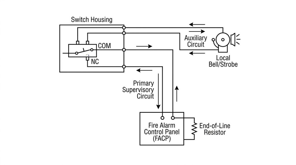
Wiring a butterfly valve with tamper switch requires connecting the internal microswitch terminals to a supervised fire alarm panel circuit. This wiring ensures that any change in the valve’s physical position is instantly detected by the central monitoring system.
Connecting the primary supervisory circuit
Think about it: the primary switch circuit connects to the fire alarm panel’s supervisory input zone to monitor the valve’s status.
- Install an end-of-line resistor (EOLR) to monitor wire integrity.
- Use normally closed (NC) contacts to maintain loop continuity.
- Connect the common (COM) wire to the panel positive lead.
Configuring the auxiliary circuit
The best part? The second switch circuit can be wired to a local alarm bell or strobe to provide an immediate onsite warning.
- Auxiliary contacts operate independently of the main panel.
- Connect local indicator lights for fast visual checks.
- Follow the wiring diagram located inside the switch cover.
| Wire Color Code | Switch Circuit | Designated Connection | Default System State |
|---|---|---|---|
| Yellow / Black | Switch 1 (Primary) | Alarm Panel Supervisory Zone | Closed Loop (Normal) |
| Red / White | Switch 1 (Primary) | Alarm Panel Zone Return | Closed Loop (Normal) |
| Blue / Orange | Switch 2 (Auxiliary) | Local Warning Bell / Strobe | Open Loop (Off-Normal) |
Always use the wiring diagram inside the switch cover to verify the correct terminal connections for your system.
Key Takeaway: Dual-circuit supervisory wiring allows for both remote monitoring and local alarms, protecting your system from unmonitored human error.
Why trust our butterfly valve with tamper switch?
You can trust our butterfly valve with tamper switch because it is manufactured under strict quality controls and holds industry-leading UL listings and FM approvals. By reviewing our butterfly valve with tamper switch in real-world installations, you can see how our designs deliver reliable performance in demanding commercial applications.
Enjoying premium manufacturing standards
Here is the thing: we build our valves with heavy-duty ductile iron and vulcanized EPDM discs to ensure long-term durability.
- Precision-ground stems prevent torque binding.
- Weatherproof actuator coatings protect internal switches from moisture.
- Each valve is pressure-tested at the factory before shipping.
Utilizing field-tested project reliability
But that is not all. Our valves are trusted by mechanical contractors and fire protection engineers globally to protect high-value assets.
- Our designs integrate seamlessly with standard commercial piping.
- We provide pre-wired switches to simplify and speed up installation.
- Our support team is always available to help with sizing and wiring.
| Valve Feature | Manufacturing Advantage | Customer Value | Project Benefit |
|---|---|---|---|
| Ductile Iron Body | High tensile strength | Impact and pressure resistance | Extended service life |
| Pre-Wired Switch | Factory-installed DPDT | Simplified electrical setup | Lower installation costs |
| UL/FM Certifications | Third-party tested | Guaranteed compliance | Fast inspector approvals |
Our commitment to premium materials and certifications ensures your system stays safe and fully code-compliant.
Key Takeaway: Choosing high-quality, certified valves helps stakeholders manage liability, simplify installation, and ensure building safety.
Can you bypass a butterfly valve with tamper switch?
You cannot bypass a butterfly valve with tamper switch without triggering an immediate supervisory alert at the main fire alarm panel. The system is designed to prevent unauthorized physical or electrical bypasses, keeping your fire protection lines continuously monitored and secure.
Preventing electrical bypass attempts
Think about it: the fire alarm panel monitors the supervisory loop’s resistance, meaning any attempt to cut or jump the wires triggers a trouble signal.
- End-of-line resistors detect circuit modifications.
- Secure conduit connections protect wiring from physical access.
- Smart panels detect wiring faults and switch issues instantly.
Implementing auxiliary bypass piping
The best part? If you must isolate the main line for servicing, you can route flow through a bypass loop controlled by supervised ball valves.
- Auxiliary bypass loops maintain continuous fire protection.
- Smaller bypass valves prevent system pressure drops.
- Every bypass valve must be supervised to maintain safety.
| Bypass Attempt Type | Protective System Feature | Panel Alarm Response | Field Resolution Action |
|---|---|---|---|
| Physical Stem Turning | Internal cam switch release | Supervisory Trouble Alert | Restore valve to fully open |
| Wiring Cut / Jump | End-of-Line Resistor monitoring | Loop Open/Short Fault | Repair and secure wiring |
| Mechanical Lockout | Padlock and chain keys | Physical lockout verification | Check operational authority |
The combination of electrical and physical safety measures prevents unmonitored line isolation.
Key Takeaway: These security measures prevent unauthorized bypass attempts, ensuring your emergency lines remain monitored and ready.
How do you size a butterfly valve with tamper switch?
To size a butterfly valve with tamper switch, you must match the valve’s nominal diameter to the pipeline size and verify that its flow coefficient (Cv) meets your system’s hydraulic requirements. Proper sizing prevents excessive pressure drops and maintains the correct flow velocity throughout your fire sprinkler lines.
Matching pipe nominal diameter
Here is the deal: the valve’s nominal size should match the diameter of the upstream and downstream piping to maintain a uniform flow path.
- Oversized valves can cause turbulent flow and pressure drops.
- Undersized valves restrict flow and increase friction losses.
- Standard sizes range from 2 inches to 12 inches.
Calculating system hydraulic demands
But that is not all. Fire protection engineers use flow coefficients (Cv) to calculate friction losses and ensure adequate water pressure reaches the sprinklers.
- High Cv ratings indicate minimal resistance to flow.
- Butterfly designs provide a clearer flow path than gate valves.
- Accurate hydraulic calculations help you pass fire code reviews.
| Nominal Size (Inches) | Average Flow Coefficient (Cv) | Maximum Flow Rate (GPM) | Friction Loss (Equivalent Pipe Feet) |
|---|---|---|---|
| 4″ (DN100) | 600 | 400 | 11 |
| 6″ (DN150) | 1,600 | 900 | 15 |
| 8″ (DN200) | 3,100 | 1,600 | 19 |
Use these flow values to complete your hydraulic calculations and select the correct valve size.
Key Takeaway: Sizing the valve to match your pipeline’s diameter and flow requirements prevents pressure loss and ensures optimal water delivery.
Securing Commercial Systems with Monitored Flow Control
Ensuring consistent water flow is the single most critical safety factor in commercial fire protection design. Standard manual valves present ongoing liability, as unmonitored maintenance errors can leave systems completely disabled. Ruitoflow solves this challenge by engineering high-performance, UL-listed, and FM-approved valves that integrate durable physical sealing with reliable, real-time electrical status monitoring. Our heavy-duty ductile iron bodies, vulcanized discs, and weatherproof supervisory switch housings deliver long-term reliability in demanding municipal and industrial environments.
We believe that fire protection systems should never suffer from unmonitored human error or equipment failures. Ruitoflow designs and builds high-quality, high-reliability flow control components that keep industrial properties and commercial spaces safe, secure, and fully code-compliant. Our engineering team stands ready to assist with sizing configurations, dual-circuit wiring layouts, and system specification requirements for your projects. Please contact us today to review your project specifications with our application engineers and secure your facility with our monitored valve options.
Frequently Asked Questions About Valve Security
Can I install a butterfly valve with tamper switch outdoors?
Yes, you can install this assembly in outdoor environments as long as the valve features a weatherproof, IP67-rated actuator enclosure. This heavy-duty housing protects the internal electrical contacts from rain and moisture to prevent corrosion.
What is the best way to verify if my valve’s microswitch has failed?
The best method is to use a digital multimeter to test electrical continuity across the primary common and normally closed terminals. You then turn the handwheel toward the closed position and verify if the switch breaks continuity within the first two full rotations.
How do I know if the tamper switch is wired to the correct alarm loop?
You can verify this by checking the status display on your main fire alarm control panel. When you turn the handwheel, the panel should immediately report a supervisory fault rather than a general trouble or active fire alarm.
Can I use a butterfly valve with tamper switch on dry sprinkler systems?
Yes, you can use these monitored valves on dry systems by installing them on the main water supply line before the dry pipe valve assembly. They provide the same continuous monitoring and safety verification as they do in wet-pipe systems.
How do I prevent false alarms during routine maintenance testing?
The most effective approach is to place the fire alarm control panel into test mode or bypass that specific supervisory zone before starting your work. This temporary step stops the system from transmitting automated alerts to local emergency services.