

Understanding the butterfly valve drawing symbol means recognizing the standardized schematic icon used to represent this quarter-turn flow control device in engineering diagrams. You sit down to review a complex piping layout, and suddenly you realize the symbols look like a confusing mess of lines and circles. Misinterpreting these icons delays commissioning, ruins expensive batches, and causes safety risks across the facility. Here is a clear guide to reading every schematic correctly so you can protect your schedule and hand over projects with complete confidence. In this guide, learning to read a butterfly valve drawing will save you time and prevent costly pipeline engineering mistakes.
1. What is a butterfly valve drawing?
A butterfly valve drawing is a visual representation on paper or digital screens that outlines the function and position of this specific valve in a fluid system. Engineers use this schematic to communicate where the quarter-turn flow control mechanism sits within the broader piping architecture. You need to grasp these visuals to ensure accurate fabrication and safe operation.
What is the valve function?
The core function shown in the schematic involves starting, regulating, or completely stopping the flow of liquids and gases. When you look at the diagram, the indicated disc turns 90 degrees to allow or block the medium. But here’s the kicker… reading this correctly prevents catastrophic flow failures in high-pressure applications.
- Starts media flow
- Regulates fluid pressure
- Stops pipeline flow completely
Key Takeaway: Identifying the basic function from the schematic helps you maintain optimal flow control and prevents costly operational errors.
Why are these diagrams used?
Designers rely on these diagrams to create a universal language across different international teams and facilities. You can easily communicate complex piping configurations without needing paragraphs of text. What’s the real story? The schematic prevents miscommunication between the design office and the installation crew on the ground.
- Standardizes communication
- Speeds up installation
- Reduces fabrication errors
Key Takeaway: Relying on standardized diagrams ensures your entire engineering team stays aligned, reducing rework and saving project budgets.
2. Why is a butterfly valve drawing vital?
A butterfly valve drawing is vital because it acts as the definitive blueprint for assembling, operating, and maintaining industrial piping networks safely. Without this critical visual guide, construction teams would guess the valve orientation, leading to immediate system failures upon startup. You need these documents to verify that the specified components match the physical reality of the plant.
How do symbols prevent errors?
Specific symbols provide exact details about valve type, end connections, and normal operating status. You can see at a glance whether the system requires a flanged, welded, or wafer configuration. Ready for the good part? This clarity eliminates the guesswork that usually ruins tight commissioning schedules.
- Clarifies connection types
- Shows default valve states
- Identifies actuator needs
Key Takeaway: Using accurate symbols prevents incorrect component orders and eliminates dangerous mismatched installations in your facility.
Can misinterpretation cost money?
Misreading the schematic directly leads to ordering the wrong components and installing valves backward against the flow direction. You will face immediate leaks, pressure drops, and forced plant shutdowns to fix the mistakes. This is where it gets interesting… fixing a single incorrect valve installation can cost thousands in lost production time.
- Leads to wrong orders
- Causes system downtime
- Increases labor expenses
Key Takeaway: Training your team to interpret schematics accurately safeguards your operational budget and keeps production running smoothly.
3. How to read a butterfly valve drawing?
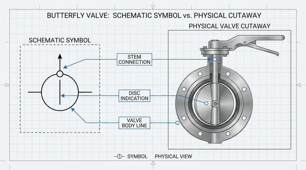
To read a butterfly valve drawing, you must identify the simplified geometric shapes that represent the main body, the central disc, and the operating stem. Recognizing these standard shapes allows you to determine how the valve operates and how it connects to the adjacent pipes. You will find that these diagrams use a minimalist approach to convey maximum engineering data.
What are the common elements?
The most common visual elements include a vertical line for the body and a diagonal line denoting the rotating disc. You will also see a solid dot or small circle representing the stem connecting the actuator to the disc. But here’s the kicker… knowing these shapes instantly tells you how the fluid behaves when it hits the valve.
- Vertical body line
- Diagonal disc line
- Solid stem circle
Key Takeaway: Memorizing the basic geometric elements helps you quickly scan and understand massive engineering blueprints without confusion.
How is the disc shown?
The disc is typically depicted as a line crossing the center of the valve body symbol. When you see this line parallel to the pipe, it means the valve is normally open. What’s the real story? The angle of this single line dictates the entire operational logic of that pipeline section.
- Parallel means open
- Perpendicular means closed
- Diagonal indicates throttling
Key Takeaway: Spotting the disc orientation immediately informs you about the default flow status, ensuring safe startup procedures.
| Element | Description | Meaning |
|---|---|---|
| Vertical Line | Main valve body | Housing of the unit |
| Diagonal Line | Internal disc | Flow control mechanism |
| Solid Dot | Operating stem | Connection to actuator |
The data in this table clearly shows how each geometric shape directly corresponds to a physical valve component.
4. What are P&ID butterfly valve drawing rules?
P&ID rules for a butterfly valve drawing dictate how these components are laid out in relation to instruments, piping, and other process equipment. These guidelines ensure that every engineer reads the serial relationship between the hardware in the exact same way. You must adhere to these rules to maintain the integrity of the process documentation.
What is P&ID symbology?
P&ID symbology is a standardized graphic language used in the process industry to map out complex industrial systems. You use these specific icons to show the transition of fluids through various stages of pressure and temperature. Ready for the good part? Mastering this language makes troubleshooting complex fluid systems incredibly fast and efficient.
- Maps out processes
- Shows instrument links
- Details flow direction
Key Takeaway: Understanding P&ID symbology equips you with the analytical skills needed to diagnose pipeline issues rapidly.
How do open and closed differ?
In a P&ID, the visual difference between an open and closed state relies on the shading or the angle of the internal lines. You will notice that normally closed valves often feature darkened or fully colored symbols to stand out. This is where it gets interesting… this simple color difference prevents operators from accidentally pressurizing isolated zones.
- Open uses clear shapes
- Closed uses dark shapes
- Status prevents accidents
Key Takeaway: Distinguishing between open and closed symbols keeps your team safe by preventing unexpected pressure releases during maintenance.
5. Which ISO standards guide a butterfly valve drawing?
ISO 10628 and ISO 14617 are the primary international standards that guide a butterfly valve drawing on a global scale. These frameworks provide a unified set of rules so that a schematic drawn in Germany can be perfectly understood in Singapore. You must follow these global guidelines if you intend to supply or maintain equipment for multinational projects.
What is ISO 10628?
ISO 10628 specifies the general rules for creating flow diagrams for chemical and petrochemical industry plants. You rely on this document to guarantee that your visual representations meet strict international safety codes. But here’s the kicker… strict compliance with this standard is often a legal requirement for large industrial contracts.
- Dictates diagram rules
- Ensures safety compliance
- Required for contracts
Key Takeaway: Following ISO 10628 ensures your design documents pass international audits and meet rigorous legal safety requirements.
How does global standard help?
A global standard eliminates regional drafting quirks that cause costly misunderstandings during international procurement. You can confidently source components from overseas suppliers knowing they are reading the exact same specifications. What’s the real story? Unified standards drastically reduce the engineering lead time for cross-border industrial builds.
- Removes regional confusion
- Aids overseas sourcing
- Reduces project delays
Key Takeaway: Adopting global standards streamlines your supply chain and prevents expensive communication breakdowns with international vendors.
| Standard | Scope | Primary Industry |
|---|---|---|
| ISO 10628 | Flow diagrams rules | Chemical processing |
| ISO 14617 | Graphical symbols | General engineering |
| ISO 9001 | Quality management | Manufacturing |
This breakdown highlights how different ISO frameworks govern specific aspects of diagram creation and quality control.
6. How do ANSI/ASME shape a butterfly valve drawing?
ANSI/ASME standards shape a butterfly valve drawing by establishing the strict formatting rules widely mandated across North American engineering projects. These regulations dictate line weights, symbol proportions, and specific annotations required for municipal and industrial piping systems. You need to apply these exact formats to win bids and pass inspections in the United States and Canada.
What is ANSI/ASME Y32.2?
ANSI/ASME Y32.2 is the definitive manual that lists graphical symbols for pipe fittings, valves, and related piping components. You use this manual as a reference dictionary whenever you draft or review a North American schematic. Ready for the good part? This manual standardizes everything, so you never have to guess what a bizarre shape means.
- Lists graphical symbols
- Standardizes annotations
- Acts as a dictionary
Key Takeaway: Keeping the ANSI/ASME Y32.2 manual handy ensures your drawings are always accurate and compliant with regional codes.
Why follow North American rules?
Following these specific rules ensures seamless integration when working with EPC contractors based in North America. You avoid the headache of redrawing entire system schematics just because the symbols do not match the local software libraries. This is where it gets interesting… local inspectors will outright reject non-compliant drawings, halting construction immediately.
- Satisfies local inspectors
- Integrates with EPCs
- Prevents drawing rejection
Key Takeaway: Sticking to North American drafting rules keeps your projects on schedule by avoiding frustrating regulatory roadblocks and rejections.
| Standard | Focus Area | Region |
|---|---|---|
| ANSI Y32.2 | Pipe fitting symbols | North America |
| ASME B16.34 | Pressure ratings | North America |
| API 609 | Component dimensions | Global/US |
The metrics in this table clarify which American standard to reference based on the specific engineering requirement.
7. What DIN rules affect a butterfly valve drawing?
DIN rules affect a butterfly valve drawing by enforcing the rigorous precision drafting standards developed by the German Institute for Standardization. These rules heavily influence process engineering projects throughout Europe and dictate how symbols interact with flow lines. You must master these specific layouts to successfully participate in European industrial and municipal engineering contracts.
What is DIN 19227?
DIN 19227 is the traditional German standard that governs the graphical representation of control systems and instrumentation. You use this guideline to ensure your automated valve symbols correctly display their feedback loops and control signals. But here’s the kicker… mastering this standard is essential for working on advanced European chemical plants.
- Governs graphical controls
- Shows feedback loops
- Essential for automation
Key Takeaway: Applying DIN 19227 correctly allows you to map out complex automated control systems with absolute clarity.
Where are DIN standards applied?
These standards are predominantly applied in machinery, automotive, and heavy chemical processing facilities across Europe. You will encounter them whenever you upgrade legacy systems that were originally built by German engineering firms. What’s the real story? Knowing DIN gives you a massive competitive advantage when bidding on European infrastructure overhauls.
- European chemical plants
- Automotive manufacturing
- Legacy system upgrades
Key Takeaway: Expertise in DIN standards opens up lucrative opportunities for your firm in the highly regulated European engineering market.
8. How is a pneumatic butterfly valve drawing made?
A pneumatic butterfly valve drawing is made by taking the standard quarter-turn symbol and adding a specific modifier that denotes an air-driven actuator. This addition clearly communicates that the mechanism requires a compressed air supply line to function properly. You must draw this accurately so the installation team routes the air lines to the correct locations.
What indicates compressed air?
A small square or semi-circle placed on top of the valve stem usually indicates a pneumatic actuator. You draw a dashed line connecting to this shape to represent the incoming compressed air signal. Ready for the good part? This clear visual distinction prevents operators from confusing it with electrically driven components.
- Square actuator symbol
- Dashed signal lines
- Placed on valve stem
Key Takeaway: Correctly illustrating the pneumatic actuator guarantees that your assembly team builds the necessary air infrastructure without delays.
Why use specific actuator marks?
Specific actuator marks tell the control systems engineer exactly what kind of output signal the plant PLC needs to generate. You use these marks to ensure the hardware matches the software programming of the facility. This is where it gets interesting… a mismatched actuator symbol can cause complete automation failures during commissioning.
- Guides PLC programming
- Matches hardware types
- Prevents automation errors
Key Takeaway: Precise actuator symbols ensure your physical piping perfectly syncs with the digital control systems, enabling smooth operations.
| Actuator Type | Symbol Modifier | Power Source |
|---|---|---|
| Pneumatic | Square or semi-circle | Compressed air |
| Electric | Box with ‘M’ or ‘E’ | Electrical grid |
| Hydraulic | Cylinder with arrows | Pressurized fluid |
This comparison table provides a quick reference for identifying different automated power sources on a complex diagram.
9. What defines an electric butterfly valve drawing?
An electric butterfly valve drawing is defined by the integration of motor annotations attached to the standard valve body icon. This schematic setup informs the electrical engineering team that they need to run power cables and control wires to this specific node. You must include these details to coordinate the mechanical and electrical installation schedules effectively.
How are motor symbols added?
Motor symbols are typically drawn as a box containing the letter “M” mounted directly above the valve stem. You route solid lines to this box to indicate the necessary electrical power and control connections. But here’s the kicker… forgetting this simple letter can cause the electrical team to completely bypass the valve during wiring.
- Box with letter M
- Solid power lines
- Mounted above stem
Key Takeaway: Accurately adding motor symbols ensures seamless collaboration between your mechanical designers and electrical wiring crews.
What labels identify electric?
Labels identifying the electric nature often include voltage requirements, phase details, and fail-safe status directly adjacent to the symbol. You read these labels to determine if the motor requires standard 110V power or industrial 480V three-phase connections. What’s the real story? Detailed labels prevent catastrophic electrical shorts and motor burnouts upon initial system power-up.
- Voltage requirements
- Phase details listed
- Fail-safe status noted
Key Takeaway: Providing precise electrical labels on your diagrams protects your expensive motorized equipment from fatal power mismatches.
10. How to spot a manual gear butterfly valve drawing?
You spot a manual gear butterfly valve drawing by looking for the standard valve icon accompanied by a distinct handwheel or gearbox symbol. This indicates that a human operator must physically turn a wheel to change the fluid flow state. You use this symbol to plan for adequate physical clearance around the pipeline for maintenance personnel.
What does the handwheel mean?
The handwheel symbol means the valve lacks automation and relies entirely on manual labor for operation. You often see this on large-diameter pipes where the pressure requires a mechanical advantage to overcome. Ready for the good part? Spotting this helps you plan safe walking platforms and access ladders for the operators.
- Indicates manual labor
- Suggests mechanical advantage
- Requires physical access
Key Takeaway: Identifying handwheel symbols allows you to design better ergonomics and safer access points for your plant workers.
Why show gearbox operations?
Showing the gearbox operation warns the engineering team that the valve takes time and effort to open or close fully. You include this to highlight that the specific line cannot be shut down instantaneously in an emergency. This is where it gets interesting… knowing the manual operation time is critical for writing accurate emergency response procedures.
- Warns of slow operation
- Highlights manual effort
- Aids emergency planning
Key Takeaway: Highlighting gearbox operations ensures your safety engineers develop realistic and effective emergency shutdown protocols for the facility.
| Valve Operation | Symbol Feature | Speed of Action |
|---|---|---|
| Manual Lever | Straight line | Fast |
| Manual Gear | Handwheel shape | Slow |
| Automated | Actuator box | Variable/Fast |
The analysis of this table quickly shows how the operation method directly impacts the response speed of the fluid system.
Mastering Your Valve Drafting Skills
Accurate symbol interpretation prevents costly installation errors, aligns global engineering teams, and ensures rigorous safety compliance across all fluid control projects. We resolve the chaos of mismatched standards and missing documentation by delivering precision-engineered valves with 100% complete, bilingual QA dossiers and standardized CAD files per lot. We provide the reliable components and exact documentation you need to protect your commissioning schedule and pass strict EPC audits. When you are ready to upgrade your pipeline reliability and eliminate handover delays, contact us today for a technical consultation. We engineer precision flow solutions that safeguard your critical industrial operations for decades.
FAQ
Q1: What is a butterfly valve drawing?
It is a visual representation on technical diagrams used to outline the function and position of this quarter-turn flow control device. It standardizes communication across engineering teams to prevent costly installation errors.
Q2: Can I misinterpret the symbols easily?
Yes, you can easily misinterpret them if you ignore regional standards like DIN or ANSI. Misinterpretation leads to wrong component orders and dangerous pipeline pressure failures.
Q3: How do I know if the valve is open or closed?
You look at the disc line orientation relative to the pipe flow direction. A parallel line means it is open, while a perpendicular line indicates it is fully closed.
Q4: What’s the best way to identify a pneumatic actuator?
You check for a small square or semi-circle symbol on the valve stem accompanied by a dashed signal line. This clearly denotes the need for a compressed air supply.
Q5: Why is accurate interpretation so critical?
It is critical because it ensures correct hardware installation and prevents potential safety hazards. Accurate reading safeguards your project budget and keeps production running without interruptions.