
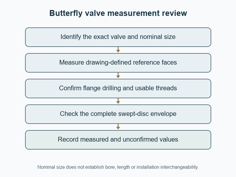
Measure a butterfly valve by confirming its nominal size, connection pattern, face-to-face length and operating clearances against the approved drawing. If you are checking "how to measure butterfly valve size" for a replacement, photograph the identification plate before reaching for a ruler. A valve can share the old unit's nominal size and still fail to fit between the existing flanges.
1. What should you identify before measuring the valve?
Identify the valve's manufacturer, nominal size, pressure designation and body connection before measuring individual features. The nameplate and casting marks give you a starting point for finding the correct drawing, although damaged or replaced parts can complicate identification. Record the serial number and any drawing revision that accompanies the installed unit. A purchase description such as 'four-inch butterfly valve' leaves the fastening arrangement, sealing faces and drive interface unresolved.
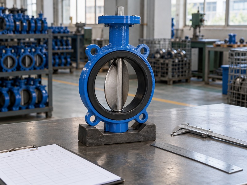
Which evidence belongs in the inspection record?
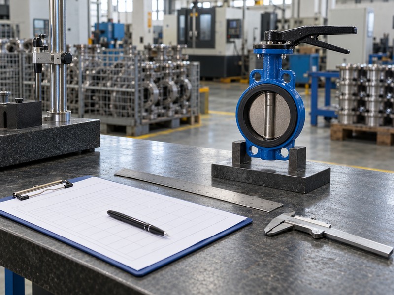
Take a front view, a side view and a close photograph of the identification plate. Include a scale beside the item when practical, but keep the camera square to the feature you want to document. A perspective photograph supports identification; it does not provide an accurate dimension by itself. Compare your observations with the existing equipment list and installation drawing, then mark missing information for a physical check rather than filling gaps from a similar catalogue image.
- Record wafer, lug, double-flanged or grooved construction.
- Keep the valve and actuator identification separate.
- Ask for the drawing of the exact supplied configuration.
| Record | Why it helps | Remaining check |
|---|---|---|
| DN or NPS | Identifies nominal size | Actual interface dimensions |
| Body connection | Identifies retention method | Flanges, threads or groove details |
| Serial and revision | Locates the original configuration | Changes made during maintenance |
2. How to measure butterfly valve size using DN or NPS?
Use DN or NPS as a nominal designation, then verify the measured features that establish fit. DN100 and NPS4 are commonly corresponding designations, but neither promises that every internal opening measures exactly 100 mm or four inches. Seat shape, disc profile and pipe wall thickness affect the available passage. When the marking is missing, compare several measured dimensions with an identified manufacturer's drawing instead of selecting a size from the bore alone.
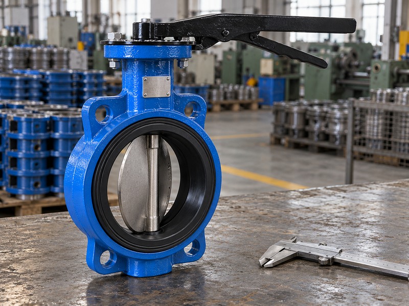
Can the bore establish nominal size on its own?
A bore measurement can narrow the possibilities, especially when supported by flange drilling and body length. It can also mislead when a liner is worn, swollen or compressed. ISO 6708 defines the DN designation system for pipework components; use it to keep nominal terminology separate from a measured diameter. On a lined valve, record what the instrument contacts, such as the lining surface, rather than reporting an unexplained 'valve diameter' that another engineer cannot reproduce.
- State the nominal designation exactly as marked.
- Label bore measurements with their physical contact surfaces.
- Record millimetres or inches beside every measured value.
| Term | What to record | Avoid assuming |
|---|---|---|
| DN | Nominal size designation | Exact bore in millimetres |
| NPS | Nominal pipe size designation | Exact bore in inches |
| Measured opening | Contact surfaces and units | Automatic interchangeability |
3. How do you measure the face-to-face length?
Measure face-to-face length along the pipe axis between the specified end-face reference planes. Use the drawing to establish those planes before placing the instrument. A soft seat can project beyond the metal body, and its installed compression can affect the assembly dimension. Measuring the casting alone may therefore omit a sealing feature that occupies space between the mating flanges. Record whether the valve is loose or installed when you report the result.
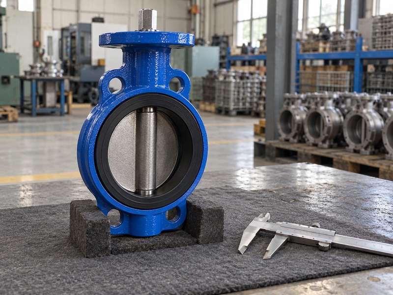
Which length should the replacement match?
The replacement must match the required installed arrangement, including the approved gasket or resilient-facing condition. Review the applicable dimensional standard and series alongside the manufacturer's drawing; a short wafer body and a double-flanged body cannot share a length merely because their DN values match. RUITO's wafer butterfly valve interface should be checked against its own approved dimensions. For an existing installation, measure the available flange gap separately and document any misalignment or unusual seal stack.
- Identify the drawing's reference faces.
- Measure parallel to the flow axis at several positions.
- Report free-state and installed dimensions separately when relevant.
| Measurement | Reference | Common omission |
|---|---|---|
| Metal body length | Casting or machined body faces | Projecting resilient faces |
| Specified face-to-face | Drawing-defined end planes | Required installation condition |
| Available flange gap | Existing mating flange faces | Alignment and seal arrangement |
4. Which flange dimensions prove the connection will fit?
Check the flange standard, pressure designation, outside diameter, hole count, hole diameter and pitch circle diameter as one pattern. A matching outside diameter cannot establish compatibility, and a bolt that passes through two holes does not prove that the joint is correct. Note the flange material and facing form as well. The valve's sealing arrangement needs a suitable contact area, while the disc needs sufficient clearance through the mating bore.
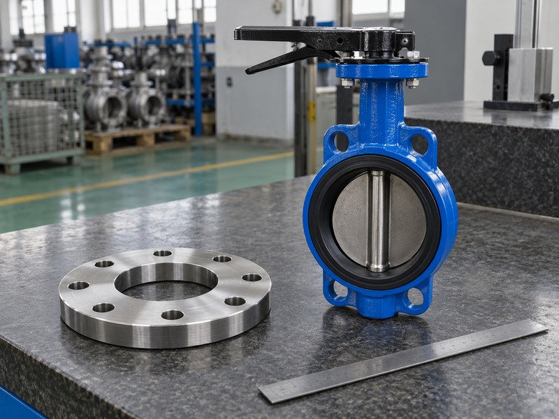
How can you check the bolt circle accurately?
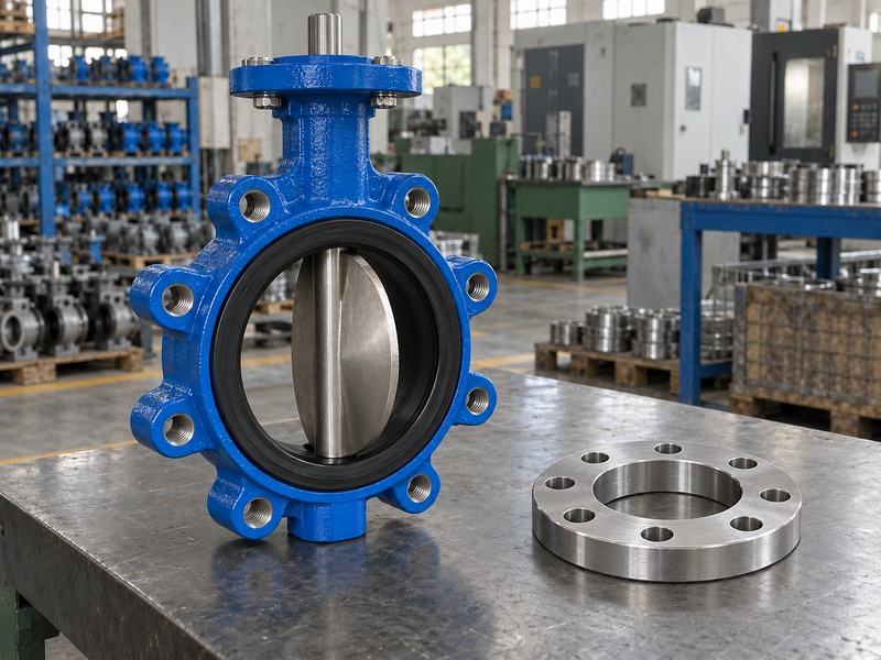
On a pattern with diametrically opposite holes, measure between their centres or derive that centre distance from clean, equal-sized hole edges. Adjacent-hole spacing is a chord rather than the full pitch circle diameter. If you use it for a calculation, record the hole count and calculation method so another reviewer can check the result. For threaded lugs, add thread diameter, pitch, available depth and the approved engagement requirement; do not treat a tapped hole as an ordinary clearance hole.
- Count all holes and note whether they are threaded.
- Confirm the standard and pressure class independently of appearance.
- Measure the mating bore as well as the external drilling.
| Feature | Instrument or record | Fit decision |
|---|---|---|
| Bolt circle and holes | Caliper and drilling drawing | Pattern alignment |
| Lug threads | Thread gauge and depth check | Correct fastener engagement |
| Facing and bore | Approved joint drawing | Sealing contact and disc clearance |
5. How do you check clearance for the opening disc?
Compare the complete swept-disc envelope with the actual internal profile of the adjacent pipe and components. A butterfly valve disc can project beyond the short body as it opens. Pipe lining, heavy walls, weld intrusion and a nearby reducer may enter that space even when the flange pattern matches. Obtain the disc clearance information for the exact valve size and construction rather than calculating it from nominal diameter alone.
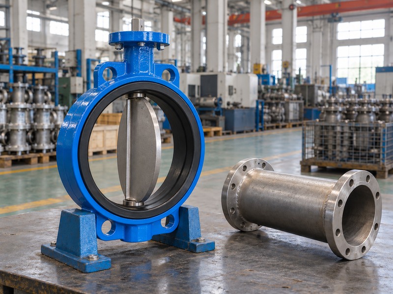
What should a clearance survey include?
Record the nearest obstruction on both sides, its internal diameter and its distance from the valve reference face. A straight cylindrical bore and a reducer with a taper need different descriptions. Use the supplier's installation procedure for any travel check on isolated, depressurized equipment, and keep tools and hands outside the disc path. If movement becomes tight, stop and find the cause. Higher actuator torque cannot correct physical interference between the disc and connected piping.
- Check upstream and downstream obstructions.
- Include linings, reducers and adjacent equipment.
- Document clearance through the approved travel range.
| Obstacle | Dimension to record | Possible result |
|---|---|---|
| Lined pipe | Minimum internal profile | Disc edge contact |
| Reducer | Taper and distance from valve | Interference during opening |
| Adjacent equipment | Internal projection and spacing | Restricted travel or damaged parts |
6. What stem and actuator dimensions should you measure?
Measure the stem's drive form, engagement length and mounting interface when the existing operator or actuator must be retained. A square stem needs its across-flats dimension; a round keyed stem needs diameter and keyway details. Record the height from the mounting reference face to the stem end. These measurements establish the mechanical interface, while operating torque and allowable stem torque remain separate engineering inputs.
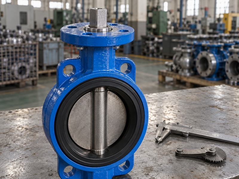
Does a matching mounting flange complete the check?
No. A mounting pattern can align while the coupling bottoms out, engages too little or places unwanted axial load on the shaft. Check the bracket, coupling and fastener arrangement against the complete assembly drawing. For a lug butterfly valve with a retained actuator, also confirm orientation and travel references before reusing parts. Measure under the manufacturer's maintenance procedure; removing a drive must not release an unsupported or pressure-loaded shaft assembly.
- Identify square, keyed, splined or other drive geometry.
- Record engagement length and mounting height.
- Check torque capacity separately from dimensional fit.
| Interface | Required detail | Consequence of a mismatch |
|---|---|---|
| Drive stem | Form, size and orientation | Loose or impossible coupling fit |
| Mounting face | Hole pattern and reference height | Bracket or coupling misalignment |
| Engagement | Usable length and clearance | Bottoming or inadequate contact |
7. Can you select a replacement seat from its diameter?
Select a replacement seat by the valve's controlled part specification and drawing, using measurements to confirm identity. Inside diameter, outside profile, axial width and shaft-hole positions describe only part of the geometry. Moulded lips, backing features and interference with the disc also affect sealing and operating torque. A worn sample may no longer represent its original dimensions, particularly after heat, chemical exposure or long-term compression.
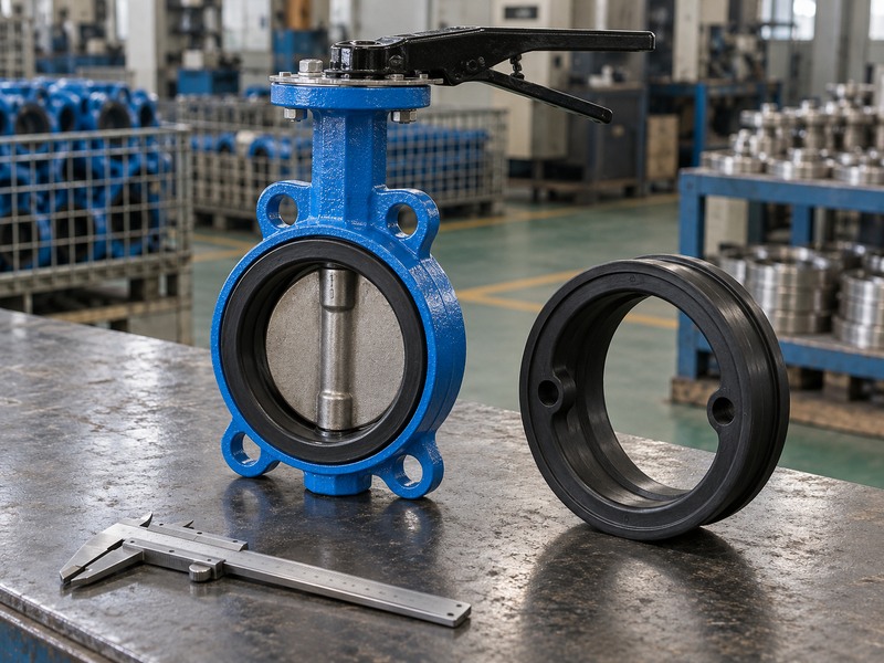
How should you document a used seat?
Record the seat's condition and photograph its cross-section and shaft-hole features without assuming that the original shape survives. Include the compound, service fluid and temperature when they are known. Do not compress a soft lip heavily with caliper jaws and report the result as an uncontrolled precise value. Ask the supplier how the spare should be identified and inspected. A visually similar elastomer ring can change both flange sealing and disc resistance after assembly.
- Use part identity and revision before dimensional resemblance.
- Record wear, swelling and permanent deformation.
- Confirm the material compound for the actual medium.
| Seat evidence | Useful observation | Limit |
|---|---|---|
| Original part record | Approved shape and compound | Must match the valve revision |
| Used sample | Profile and damage | May be permanently deformed |
| Measured dimensions | Features and inspection method | Do not establish service compatibility |
8. What can you measure while the valve remains installed?
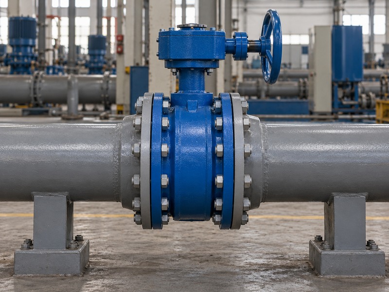
You can usually document accessible external dimensions and identification while the valve remains installed, subject to the site's working procedure. Measure body length where accessible, flange outlines, actuator height and the available maintenance space. Internal bore and disc-clearance claims need suitable drawings or an approved inspection opportunity. Insulation, guards and tightly packed pipework may hide the very features that distinguish two otherwise similar valves.
How do you avoid guessing hidden dimensions?
Separate each reported value into measured, drawing-derived or unconfirmed. A pipe's external circumference can support identification, but it does not reveal wall thickness, lining thickness or the valve bore. Use existing spool drawings and equipment records to plan what must be checked during an outage. For a double-flanged butterfly valve, include bolt-removal access and the space needed to withdraw the unit, rather than recording only the envelope it occupies during normal operation.
- Mark inaccessible dimensions as unconfirmed.
- Record insulation and guard removal needs.
- Include operator sweep and maintenance withdrawal space.
| Survey item | Often accessible | May need an outage |
|---|---|---|
| Identification and envelope | Plate, body outline and actuator height | Covered or obstructed features |
| Connection pattern | Exposed flange and bolt details | Hidden sealing faces |
| Internal clearance | Approved drawings | Direct inspection of the pipe bore |
9. What should you send before ordering the replacement?
Send a dimensioned survey, identification photographs, service conditions and the proposed replacement drawing for one coordinated review. Include normal pressure, maximum temperature, shutoff differential and any reverse-flow duty. Dimensional agreement does not qualify the seat, lining, body rating or actuator for service. Keep unresolved differences visible in the quotation and purchase order so a convenient nominal-size match does not become an unapproved substitution.
How do you close the measurement review?
Ask the supplier to return a marked drawing that identifies the dimensions and conditions accepted for the installation. State which field values are verified and which require confirmation after removal. For RUITO enquiries, contact us with the survey, fluid data and required connection so engineering can compare the proposed configuration with the available space. Release the order only after the responsible reviewer has addressed differences in face length, drilling, disc envelope and drive engagement.
- Attach units, reference faces and drawing revisions.
- Keep measured values separate from catalogue assumptions.
- Resolve interface and service deviations before release.
| Package | Include | Approval question |
|---|---|---|
| Field survey | Dimensions, photographs and uncertainty | Will the replacement physically fit? |
| Service data | Fluid, temperature and pressure cases | Is the configuration suitable? |
| Supplier response | Marked drawing and deviations | Have both parties accepted the same details? |
10. What questions arise when measuring butterfly valves?
Q1. Can I use flange outside diameter as valve size?
No. Flange outside diameter is a connection dimension. Confirm DN or NPS, then check drilling, face length and internal clearance against the correct drawing. Different pressure classes and standards can use different flange geometry for the same nominal size.
Q2. How do I know if DN100 means a 100 mm opening?
It does not guarantee that measurement. DN identifies nominal size. Seat geometry, disc construction and the connected pipe determine the actual available opening. Record the measured feature and its reference surfaces separately.
Q3. Can I measure a valve without removing it?
Yes, for accessible external features under the site's procedure. Hidden sealing faces and internal clearance may still need drawings or inspection during an outage. Label unverified dimensions rather than estimating them as confirmed values.
Q4. What's the best tool for checking lug threads?
Use an appropriate thread gauge with diameter and depth checks. Caliper diameter alone cannot distinguish thread pitch or establish usable engagement. Confirm the required bolt specification and bottom clearance from the approved joint drawing.
Q5. Can I reuse the actuator when the new valve has the same DN?
Only after checking both the interface and torque requirements. Mounting holes, stem form, coupling engagement, travel settings and operating loads can differ between valves with the same nominal size. Obtain approval for the complete replacement assembly.