
Fix selection mistakes with a "spring return manual butterfly valve" by checking what happens when the operator releases the handle. Its spring mechanism returns the disc toward a specified position without a normal powered stroke. Confirm the complete valve-handle assembly, operating effort, and release behavior before using it for filling, sampling, or another controlled manual duty.
1. What is a spring return manual butterfly valve?
A spring return manual butterfly valve combines a butterfly valve with a manual operator that stores spring energy as a person moves the handle. When the handle is released under the specified conditions, the spring drives the return movement. The intended endpoint may be open or closed according to the approved configuration. The handle, spring housing, shaft connection, stops, and valve need to be selected together so the operator can move the valve and the spring can return it.
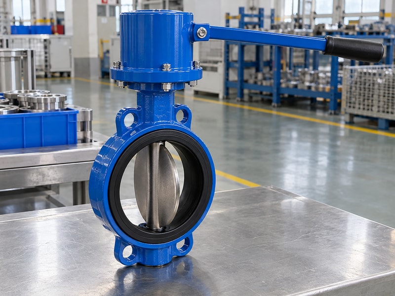
Distinguish three manual arrangements
A standard locking lever holds an adjusted position through its locking mechanism. A manual spring-return operator has a different release function. A manual override on a pneumatic or electric actuator is another arrangement and may have its own engagement and reset restrictions. Identify which is offered with the butterfly valve body rather than calling every hand-operated assembly a deadman valve.
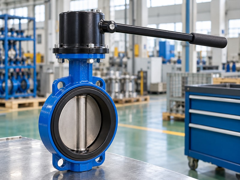
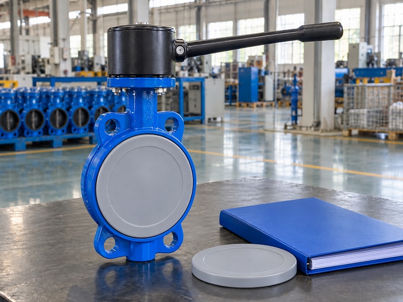
A product photograph can show the external arrangement, but the operating instructions must establish its intended release behavior.
- Identify the actual manual operator mechanism.
- Specify the spring-driven endpoint and permitted travel.
| Operator | Function to confirm |
|---|---|
| Locking lever | How a position is retained and released |
| Manual spring return | How release permits the spring-driven movement |
| Powered-actuator override | Engagement, isolation, and return to automatic service |
2. Which release position does the operation require?
The release position of a spring return manual butterfly valve should follow the actual operating sequence and process requirement. Closing on release may suit a controlled filling or sampling task when that action is specified for the system. Another duty can require a different endpoint. Define the normal starting position, permitted manual movement, release action, and the conditions for restarting.
A familiar handle style cannot establish which position is appropriate for the line.
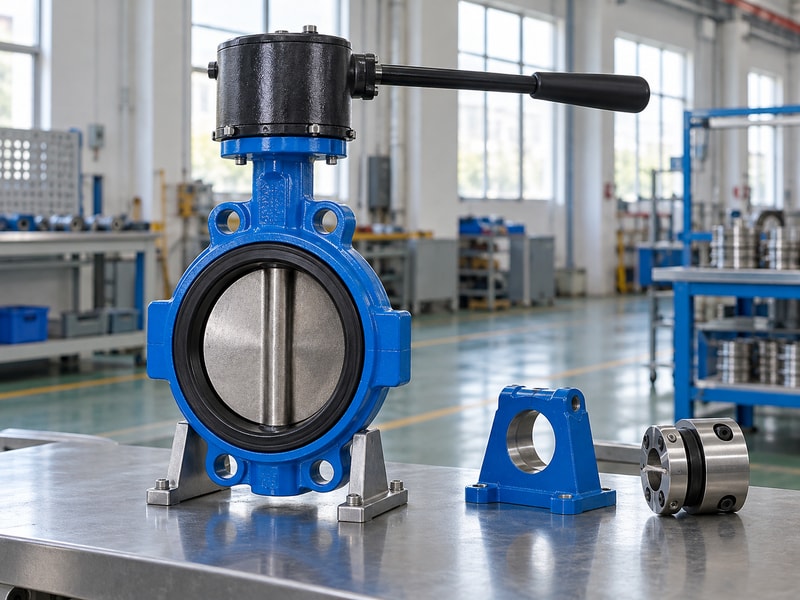
Review the complete manual task
Consider where the operator stands, what equipment is connected downstream, and what happens when the operator must let go. Account for stored process pressure and any gravity-fed supply. A manually released return does not by itself provide remote shutdown, fire response, overfill detection, or a complete safety function. Those functions require their own specified arrangements where needed.
Write the intended sequence clearly so the supplier can test the assembly and the operating procedure can describe the same behavior.
- State the endpoint after deliberate or accidental release.
- Identify functions that require separate controls or equipment.
| Task stage | Question |
|---|---|
| Starting | What valve position and process condition are required? |
| Operating | How is movement controlled and effort maintained? |
| Releasing | Which endpoint and response time are specified? |
3. How do hand effort and return torque interact?
A spring return manual butterfly valve needs enough spring output to complete the return stroke and a manual operating effort suited to the intended task. The person moving the handle must overcome the relevant valve load and spring resistance. Valve torque varies with size, seat, temperature, differential pressure, and travel position. Ask for the complete assembly's operating-effort and return basis.
An acceptable return movement does not establish that holding the handle is practical throughout the required operation.
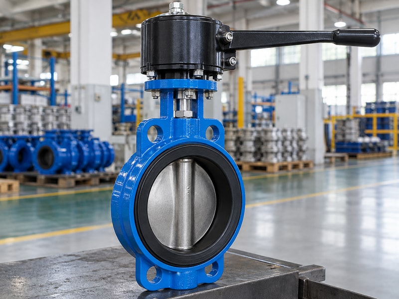
Use lever geometry as a check, not an approval
For a simple lever, torque equals perpendicular force multiplied by its effective arm. As a geometry example, 100 N applied at right angles at 0.25 m produces 25 N·m. That arithmetic does not approve the effort or size the spring. Check the actual handle geometry, changing force direction, task duration, and approved valve load.
For a lug-style valve assembly, also retain shaft and connection torque limits so a longer handle does not create an excessive mechanical load.
- Check required effort over the complete manual movement.
- Check spring return across the complete return movement.
| Requirement | Basis |
|---|---|
| Manual operation | Valve load, spring resistance, and handle geometry |
| Return | Available spring output through travel |
| Mechanical limits | Permitted handle, shaft, coupling, and mounting loads |
4. Which mounting details affect release behavior?
Mounting details affect a spring return manual butterfly valve when alignment, engagement, interference, or stop settings add resistance or change travel. Confirm the shaft shape, drive connection, fasteners, operator orientation, and mounting arrangement from the approved drawing. The spring housing needs the support and clearances specified by its manufacturer. A compatible bolt pattern alone cannot establish the correct handle sweep, spring preload, or disc endpoint for the assembled valve.
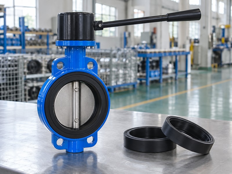
Check the installed handle sweep
Review the full movement envelope against walls, pipework, insulation, guards, and nearby equipment. Keep the operator's standing position and hand access in that review. Check the ISO 5211 attachment scope where the offered interface uses it, while retaining the assembly-specific mounting drawing. Use the manufacturer's adjustment procedure for travel and stops.
Do not compensate for an incorrectly oriented operator by forcing the handle or using an improvised extension on the lever.
- Verify engagement, alignment, and fastener requirements.
- Keep the complete handle sweep free of interference.
| Interface | Check |
|---|---|
| Shaft connection | Drive shape, engagement, orientation, and limits |
| Operator mounting | Support, fasteners, and permitted adjustment |
| Handle envelope | Hand access, standing position, and clearance |
5. How do fluid and seat choice affect manual use?
The fluid and seat configuration of a spring return manual butterfly valve affect compatibility, shutoff behavior, and operating torque. Supply the actual fluid composition, concentration, temperature, working pressure, and closing differential pressure. Include cleaning fluids and any solids that can interfere with the disc or seat. A handle selected for a clean-water assembly cannot automatically be transferred to another seat material or a chemically different duty without reviewing the changed load and material limits.
Keep operator selection tied to the valve configuration
Use configuration-specific data for the body, disc, shaft, seat, and auxiliary seals. Check any pressure-temperature derating and the permitted closing direction. The connection and operating limits of a flanged butterfly valve remain applicable after the manual operator is added. If a replacement seat changes friction or compression, the spring and manual-effort review may also change.
Keep spare parts identified by the approved configuration rather than choosing a seal solely because its dimensions or color appear similar.
- Provide fluid, temperature, and pressure cases together.
- Recheck return and effort after a seat substitution.
| Change | Possible consequence |
|---|---|
| Seat compound | Different compatibility, friction, or compression behavior |
| Fluid or temperature | Changed material limits and operating load |
| Closing differential | Changed disc and seating torque requirement |
6. What installation checks prevent unwanted interference?
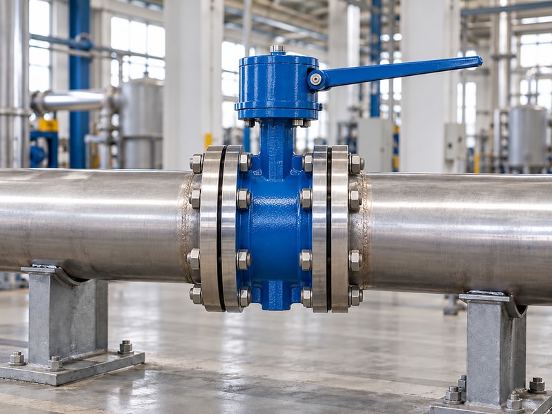
Install a spring return manual butterfly valve with the disc clearance, flange arrangement, pipe support, and operator access required by its approved configuration. Check nearby pipe bores, reducers, liners, and gaskets against the disc's opening envelope. The installed pipe joint must not distort the body or obstruct movement. Support piping independently and follow the specified lifting arrangement.
A handle that returns freely on a bench can encounter a different load after the valve is clamped into the line.
Keep access clear during the actual task
Review hoses, sample containers, nearby controls, and any removable equipment used during operation. They should not enter the handle sweep or block the operator's release path. Confirm whether any locking feature is supplied and how it affects the intended return function. A device that holds the handle open can change the operating sequence; it must be reviewed as part of the actual assembly.
Do not add improvised restraints that defeat a specified hold-to-operate arrangement.
- Verify the disc and handle movement envelopes separately.
- Review any supplied locking or retaining feature.
| Installed check | Acceptance point |
|---|---|
| Pipe connection | Correct joint, alignment, and disc clearance |
| Operator access | Clear handle sweep and usable standing position |
| Retaining devices | Behavior consistent with the approved sequence |
7. How should you test the manual return function?
Test a spring return manual butterfly valve as a complete assembly using agreed supply-independent manual operating and release conditions. Record starting position, movement, release point, return endpoint, and travel time where timing is specified. Check required operating effort under the agreed conditions. A return demonstration without valve load is useful component evidence but does not cover every installed pressure or seat condition.
Define the factory and site test boundaries before the assembly is accepted.
Do not substitute position for leakage evidence
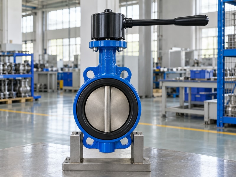
Check that the actual disc reaches the intended position and that any indication corresponds to the mechanical connection. Then perform the specified shutoff leakage test separately, using the selected method, pressure direction, conditions, and acceptance criterion. A handle reaching its stop does not prove the seat meets that criterion. If the task needs a particular return time or repeated operating pattern, include those requirements in the test plan rather than assuming that any visible spring movement is sufficient.
- Test movement and release from the relevant positions.
- Record leakage acceptance separately from return travel.
| Test | What to record |
|---|---|
| Manual movement | Effort, travel, and interference |
| Release | Starting point, endpoint, and specified time |
| Shutoff | Method, direction, conditions, and leakage result |
8. What should maintenance staff inspect?
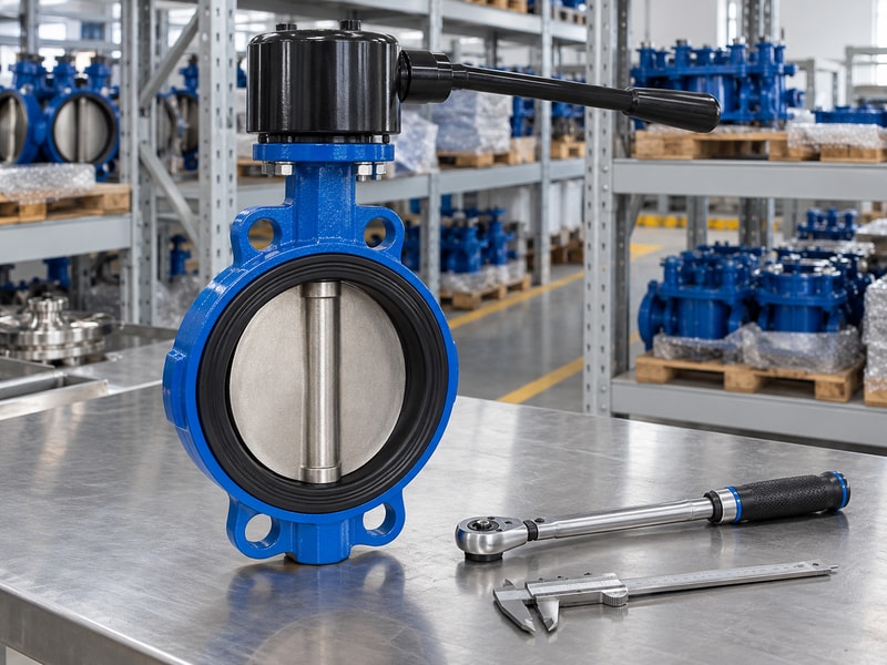
Maintenance staff should inspect a spring return manual butterfly valve for changes in operating effort, return behavior, leakage, corrosion, fastener condition, and mechanical interference. Compare findings with the commissioning record. Follow the manufacturer's isolation and stored-energy procedure before working near the handle, disc, or spring housing. The spring can retain energy after the valve is disconnected from the process.
Keep its housing closed unless the authorized service procedure covers disassembly.
Investigate changes before adjusting the spring
A slower return can result from a damaged seat, misalignment, contamination, interference, or deterioration in the operator. Increasing spring force without identifying the cause can increase manual effort and mechanical loads. After servicing the valve or replacing the operator, repeat the matching and functional checks affected by the work. Retain configuration-specific instructions and spare-part details.
Set inspection intervals from actual duty, environment, findings, and the required process response instead of promising a universal maintenance period.
- Keep a baseline for effort and return behavior.
- Use authorized procedures for stored-energy components.
| Observation | Follow-up |
|---|---|
| Rising manual effort | Inspect valve load, interference, and operator condition |
| Slower or incomplete return | Investigate resistance and spring-operator condition |
| Component replacement | Repeat affected sizing, travel, and sealing checks |
9. What belongs in the purchase and handover record?
The spring return manual butterfly valve record should define the manual task, return endpoint, operating cases, required effort basis, mounting arrangement, and acceptance conditions. Identify the valve and operator configuration on one assembly record. Request the approved drawing, material identification, operation and maintenance instructions, and agreed test results. Confirm which retaining or locking features are included and how they affect the release sequence.
Resolve those details before the package is supplied.
Ask for an assembly-specific review
Send the supplier the fluid, size, connection details, temperature, pressure, maximum closing differential, handle-space constraints, and expected manual operating pattern. Ask who matches and tests the valve-handle assembly and who approves substitutions. RUITO can review the stated valve duty and proposed operator arrangement, with availability and acceptance requirements confirmed for the order. Keep the final instructions at the point of use so the operating method reflects the delivered assembly rather than another manual valve's familiar handle behavior.
- Specify the release sequence and actual task conditions.
- Retain the complete assembly identity and instructions.
| Purchase item | Required evidence |
|---|---|
| Duty and task | Operating cases, return endpoint, and use pattern |
| Matching | Torque, effort, mounting, and clearance basis |
| Handover | Instructions, identification, and acceptance records |
10. What should operators and buyers ask about manual return?
Q1. Can I use a standard locking lever as a spring-return handle?
No. Its mechanism has a different purpose. Use an operator documented for the required manual movement and release action, matched to the valve load and interface.
Q2. Does release always close the valve?
No. The approved assembly determines its return direction. State the required endpoint and verify it under the agreed operating conditions.
Q3. Can I add a longer handle to reduce effort?
Only after the manufacturer reviews the change. Handle geometry, sweep, shaft loads, connection limits, and the return mechanism can all be affected.
Q4. How do I know whether the valve seals after release?
Use the specified leakage test. A handle or disc reaching its endpoint establishes position under the test conditions, not the separate shutoff leakage criterion.
Q5. Can I open the spring housing after removing the valve?
Only under the manufacturer's authorized service procedure. The operator can retain spring energy even when the valve is disconnected from the process.
Describe the manual task, release position, and installation space when you contact us. RUITO can review the valve duty and the proposed operator configuration before supply.