
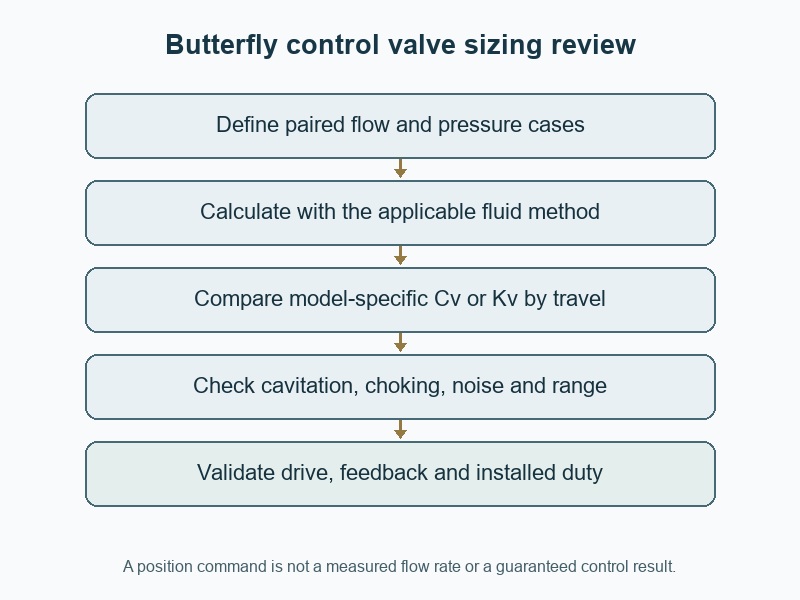
Size a butterfly control valve by matching each required flow and pressure case to the selected model's capacity, usable travel and hydraulic limits. For "how to size a butterfly control valve", begin with the process duty rather than pipe diameter. A valve that passes maximum flow can still provide poor control at the minimum operating point.
1. How to size a butterfly control valve from duty data?
Build a set of paired operating cases before selecting a nominal valve size. Each case needs flow, upstream pressure, downstream pressure, temperature and fluid properties that can occur together. Include minimum, normal and maximum demand, plus relevant start-up or upset conditions. Combining the highest flow from one condition with pressures from another can create a fictitious sizing case and lead procurement toward a valve that does not suit the actual process.
Which fluid details should the duty sheet contain?
State composition, phase, density or specific gravity, viscosity and the properties needed for the applicable hydraulic checks. Include vapour pressure for liquid evaluation and the appropriate gas or steam data when relevant. Describe solids, fibres, deposits and cleaning exposure that can affect the selected construction. Ask the supplier which assumptions remain open. A single flow number and pipe DN omit the pressure available to move that flow through the valve and the limits that may govern its operation.
- Keep each flow and pressure pair together.
- Include minimum demand as well as maximum capacity.
- Identify fluid properties and unresolved assumptions.
| Operating case | Data to pair | Selection purpose |
|---|---|---|
| Minimum | Lowest required flow and its pressures | Check useful low-flow control |
| Normal | Typical flow, pressure and temperature | Check routine travel and loading |
| Maximum or upset | Simultaneous limiting conditions | Check capacity and hydraulic limits |
2. What do Cv and Kv tell you about valve capacity?
Cv and Kv express flow capacity under defined reference conventions and units. They are not nominal pipe sizes, and they must be associated with the actual valve construction and opening. A full-open value describes only that condition. For control selection, obtain capacity by travel across the proposed operating range, along with the model-specific factors needed for the applicable fluid and installation method.
How do you avoid mixing coefficient systems?
Keep the coefficient convention and all calculation units explicit. Cv commonly uses the US-gallon-per-minute and psi reference, while Kv uses the cubic-metre-per-hour and bar reference. Do not place a Cv number into a Kv equation without the appropriate conversion and method. For a wafer butterfly valve proposed for modulation, confirm that the supplied capacity curve and permitted control range apply to its exact disc and seat, rather than transferring data from a similar-looking isolation model.
- Record coefficient convention and calculation units.
- Use capacity by travel for the selected construction.
- Confirm the model is approved for the proposed modulation duty.
| Capacity information | What it supports | What remains unresolved |
|---|---|---|
| Full-open Cv or Kv | One maximum-opening comparison | Minimum-flow controllability |
| Capacity by travel | Opening required for each case | Installed pressure behavior |
| Model-specific factors | Applicable sizing and limit checks | Complete service suitability |
3. How can you calculate a preliminary liquid Kv?
For a simplified turbulent, non-choked liquid case without attached-fitting corrections, a preliminary relationship is Kv = Q × √(SG / Δp). Here Q is in cubic metres per hour, SG is specific gravity relative to the reference water basis and Δp is in bar. Use this only within its stated assumptions. Viscosity, pressure recovery, attached fittings and other governing effects can require additional treatment before an actual valve is selected.
What does a worked screening example show?
For hypothetical water-like liquid cases with SG1, the table below gives preliminary coefficients for three paired flow and pressure-drop conditions. At 50 m³/h and 0.25 bar, the result is Kv100; the same flow at 1 bar would give Kv50. These values do not identify a DN without the selected model's curve. IEC 60534-2-1 addresses control-valve sizing equations under installed conditions; use the applicable complete method and supplier data for final selection.
- State the assumptions beside the calculation.
- Use the pressure drop belonging to each flow case.
- Complete fitting, fluid and hydraulic-limit checks before selection.
| Illustrative case | Q and Δp at SG1 | Preliminary Kv |
|---|---|---|
| Minimum | 10 m³/h and 0.8 bar | About 11.2 |
| Normal | 30 m³/h and 0.5 bar | About 42.4 |
| Maximum | 50 m³/h and 0.25 bar | 100 |
4. How do you choose DN from capacity and travel?
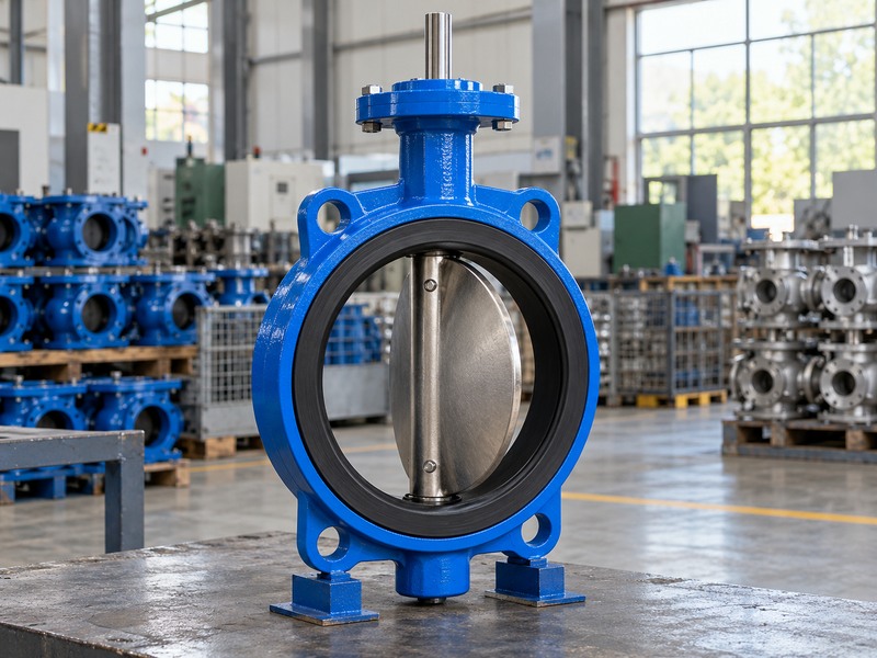
Compare the required coefficient for every case with the selected valve's capacity-by-travel data, then check that all operating points lie within its permitted useful range. A valve that reaches maximum flow only at an unacceptable opening is unsuitable, while an oversized valve may force normal operation into a narrow low-opening region. Nominal line size provides layout context, but it cannot replace the hydraulic and control review.
Can a fixed opening rule choose every valve?
Use the model's actual characteristic, allowable throttling range and process requirements instead of one universal percentage-open rule. Opening percentages can also use different references in data sheets, so confirm whether the supplied curve uses angle, travel percentage or another convention. Avoid selecting a control valve by a fixed number of nominal sizes below the pipe. Any size reduction changes velocity, attached fittings and the installed calculation, and must still provide sufficient disc clearance and a suitable maintenance arrangement.
- Locate every duty point on the accepted capacity curve.
- Confirm the opening convention and permitted range.
- Review reducers and velocity when changing valve size.
| Candidate behavior | Question to ask | Possible response |
|---|---|---|
| Maximum case near a limit | Is the required travel permitted? | Change size or construction |
| Minimum case at very small opening | Can useful control be maintained? | Review range and actuator behavior |
| Reduced valve size | Are fittings and velocity acceptable? | Recalculate the installed arrangement |
5. Why does the installed characteristic differ from the curve?
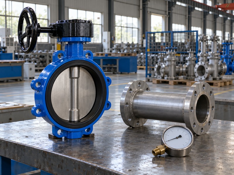
The installed flow response depends on how the pressure available across the valve changes with flow and the rest of the system. A catalogue characteristic usually has a defined reference basis that does not reproduce every pump and pipe network. As pipe losses, pump operation or other control elements change, the same disc movement can produce a different flow change. Review the valve as part of the intended system rather than selecting its characteristic in isolation.
Which system information improves the review?
Provide pump or source-pressure behavior, downstream requirements, relevant line losses and the operating modes that can alter available pressure. Keep attached reducer and expander information in the sizing model where the method requires it. Do not assign one arbitrary valve pressure drop to every flow point. If the process needs a defined controllable range, ask the supplier and system engineer to evaluate the combined response, including the actuator's positioning behavior and any feedback arrangement used by the controller.
- Supply pressure behavior for the whole operating range.
- Include attached fittings in the applicable method.
- Evaluate the combined valve, actuator and system response.
| System input | What can change | Effect on selection |
|---|---|---|
| Pump or source behavior | Available differential pressure | Required capacity at each case |
| Pipe and fitting losses | Pressure distribution with flow | Installed response |
| Operating modes | Simultaneous system conditions | Usable control range and limits |
6. Which hydraulic limits can reject a candidate size?
Cavitation, flashing, choking, noise, velocity and unsuitable fluid conditions can reject a candidate even when its nominal capacity appears sufficient. Liquid pressure recovery and vapour pressure affect the assessment, while compressible flow needs its own applicable method and fluid properties. A simple liquid square-root relationship cannot be transferred to gas or steam sizing. Obtain the selected model's relevant factors and limits rather than treating a computed coefficient as the final approval.
Why are absolute pressures needed for some checks?
A pressure difference describes the drop across the valve, but checks involving vapour formation or compressible behavior also need the appropriate absolute pressures and temperature-dependent properties. State bar(a) or another explicit absolute unit where required, and keep gauge values clearly labelled. If the process falls outside the model's acceptable range, consider another construction or a reviewed system change. Increasing actuator torque or adding a positioner does not remove a hydraulic limit inside the valve.
- Check the governing hydraulic limits for each case.
- Use the correct fluid and pressure conventions.
- Treat an unsuitable condition as a selection issue, not a control-setting issue.
| Limit review | Data required | Why capacity alone fails |
|---|---|---|
| Cavitation or flashing | Absolute pressures, temperature and liquid properties | Local phase change can govern |
| Compressible choking | Applicable gas or steam inputs and factors | Liquid equations do not apply |
| Noise and velocity | Model and operating-case data | Passing the flow may still be unacceptable |
7. How do you size the actuator for control duty?
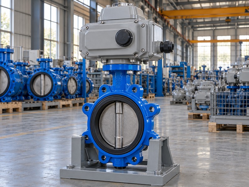
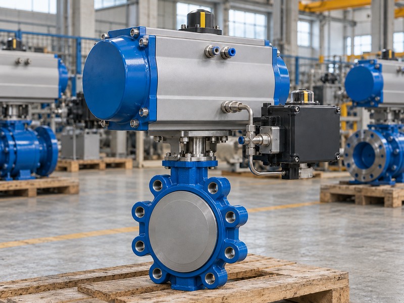
Size the actuator for torque throughout the permitted control range and the required end strokes, then verify positioning and duty capability. Include minimum supply, maximum differential, required speed and the agreed loss-event response. Modulation can require frequent corrections that an occasional open-close drive is not rated to perform. The complete valve, bracket, coupling and actuator must also remain within their accepted mechanical limits.
Does a precise position signal guarantee precise flow?
Position feedback describes the checked valve or actuator position, while actual flow also depends on pressure, fluid properties and the installed characteristic. Deadband, backlash and friction can affect small positioning changes, particularly where the valve's flow response is steep. For a lug butterfly valve control package, coordinate the mechanical mounting and torque review with the required positioning behavior. Confirm which feedback the process needs and verify it under the agreed acceptance procedure rather than promising a generic flow accuracy from the signal resolution.
- Match torque and cycling duty to the actual control task.
- Check deadband, backlash and usable positioning performance.
- Keep position accuracy separate from measured flow accuracy.
| Actuation check | Required basis | Unresolved by a position signal |
|---|---|---|
| Torque and supply | Demand across the stroke | Ability to move under process load |
| Duty and speed | Expected corrections and cycles | Thermal or pneumatic suitability |
| Positioning behavior | Accepted complete assembly | Actual process flow accuracy |
8. Which material and installation checks remain?
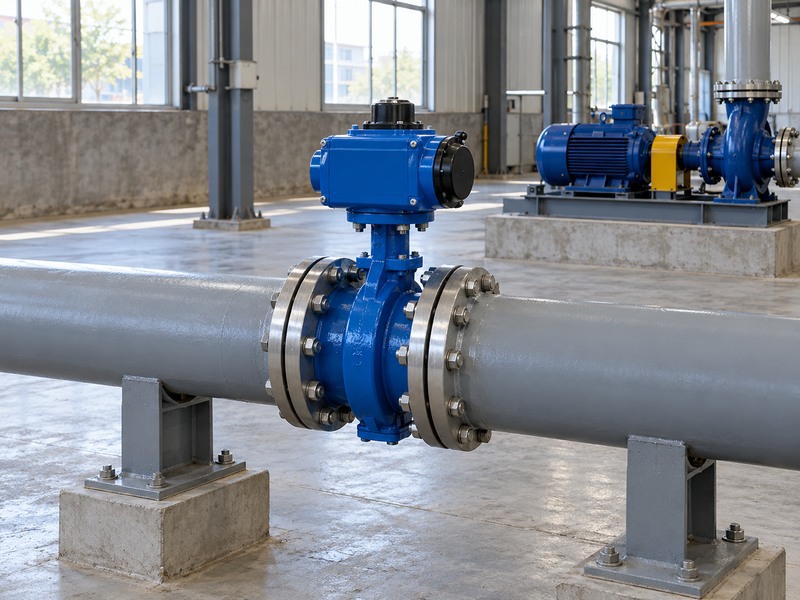
The selected capacity still needs a suitable body, seat, shaft, pressure-temperature rating and installation interface. Confirm the complete wetted material list for the actual fluid and cleaning exposure. Check flange drilling, face length, disc envelope, operator space and pipe support. A hydraulic calculation does not qualify a water-service seat for chemical liquid or establish that the moving disc clears a nearby reducer.
How should construction changes be controlled?
Keep the capacity curve and sizing factors linked to the exact proposed construction. Changing disc geometry, seat type, liner or body size can alter both hydraulic and torque data. For a flanged butterfly valve alternative, review direction-specific closure limits and the complete interface rather than treating it as a geometric substitute. Record changes after approval and reassess the affected sizing, mounting and service checks before releasing a revised assembly for manufacture or installation.
- Link hydraulic data to the supplied construction.
- Review materials and physical fit separately.
- Recalculate affected cases after a configuration change.
| Configuration change | Review again | Reason |
|---|---|---|
| Disc or body size | Capacity, factors and travel | Hydraulic response can change |
| Seat or lining | Compatibility, rating and torque | Service and drive loads can change |
| Connection or operator | Fit, clearance and mounting | Installation behavior can change |
9. What should the control-valve enquiry and acceptance include?
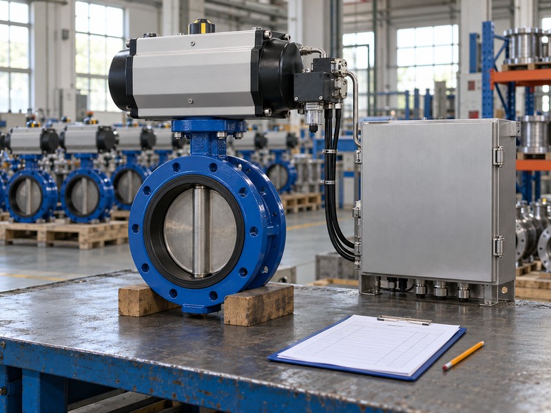
Include paired duty cases, fluid properties, piping arrangement, required controllable range, hydraulic limits and control functions. Add material, connection, drive supply, timing, feedback and loss-event requirements. Ask the supplier to return the selected construction and operating points with its calculation assumptions and deviations. This creates a reviewable selection rather than a nominal size accompanied by an unsupported promise of stable control.
How do you verify the installed result?
For RUITO enquiries, contact us with the process duty and layout so engineering can assess the proposed butterfly valve and drive configuration. Agree acceptance checks for travel, feedback, response and the process operating range, with the test conditions recorded. Commission the installed package using the accepted procedure and review any difference between calculated and observed behavior. Retain the sizing record so later changes in fluid, pressure, control mode or required flow trigger the appropriate reassessment.
- Keep assumptions and deviations visible in the quotation.
- Agree measurable acceptance conditions before release.
- Retain the sizing basis for later process changes.
| Review stage | Required evidence | Decision |
|---|---|---|
| Selection | Cases, calculation and model data | Suitable candidate and travel range |
| Assembly acceptance | Mounting, settings and functional checks | Package matches the agreed configuration |
| Commissioning | Recorded installed operating conditions | Required process behavior demonstrated |
10. What questions arise when sizing butterfly control valves?
Q1. Can I size a control valve from the pipe DN?
Use pipe DN as installation context. Select the valve using paired duty cases, model-specific capacity by travel and hydraulic limits. A line-sized valve can be too large for useful low-flow control.
Q2. How do I know whether the selected opening range is suitable?
Locate every operating case on the accepted model curve and compare it with the supplier's permitted range and process requirements. A fixed percentage-open rule does not qualify every butterfly valve.
Q3. Can I use the simple liquid Kv equation for compressed air?
No. Compressible flow requires the applicable method and appropriate absolute pressures, temperature and gas properties. A liquid screening relationship does not describe gas choking or expansion.
Q4. What's the best way to reduce hunting at low flow?
Check the installed characteristic, valve sizing and actuator positioning behavior with the system engineer. Controller tuning alone may not resolve an oversized valve, friction, backlash or an unsuitable operating point.
Q5. Can a positioner prevent cavitation?
No. A positioner controls the actuator's position according to its configuration. Cavitation depends on fluid properties, pressure conditions and valve hydraulics, which require a suitable selection or system change.