
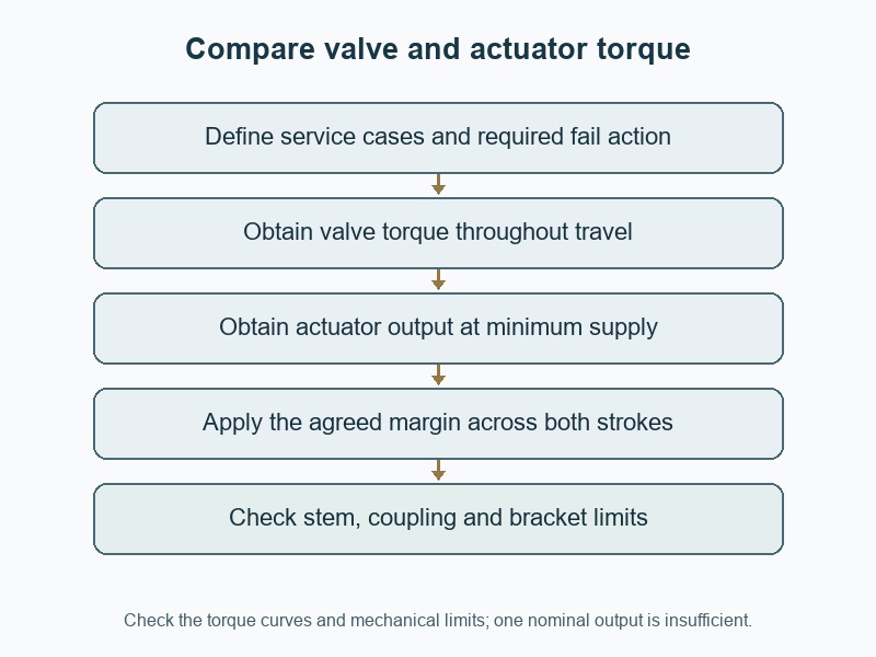
Size the actuator by comparing its available output with the valve's required torque throughout every specified operating stroke. To check "how to size an actuator for a butterfly valve", obtain the duty-specific valve torque before selecting a drive. A nominal actuator rating can look adequate while its minimum-supply or spring-return output falls short where the valve needs it.
1. How to size an actuator for a butterfly valve?
Start with the valve's required torque curve and the operating cases it must satisfy. Include unseating, running and seating loads for the actual seat, size, temperature, fluid and differential pressure. Confirm pressure direction and whether the valve operates after long idle periods. The actuator selection needs those inputs before its catalogue output can be compared meaningfully; matching the valve DN to an actuator model name cannot establish the required torque.
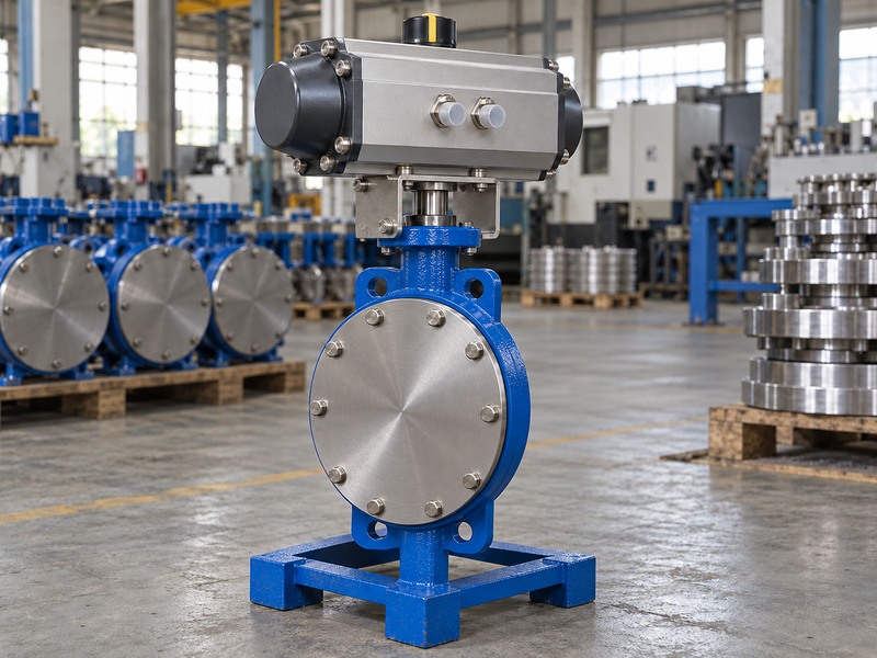
Which operating cases should the supplier evaluate?
List normal cycling, maximum closing differential, reverse pressure, start-up and the required loss-of-energy action. State whether deposits, solids or long dwell periods are part of the intended service, then ask how the valve torque data accounts for them. Avoid adding an arbitrary allowance to an unidentified dry-bench torque. The valve supplier should identify the torque basis and any limitations, while the actuator supplier confirms output under the available supply conditions and the complete stroke requirements.
- Obtain torque data for the exact valve configuration.
- Separate operating and fail-action cases.
- Record the assumptions behind every torque allowance.
| Input | What to specify | Why it changes sizing |
|---|---|---|
| Valve configuration | Disc, seat, shaft and size | Determines mechanical resistance |
| Service case | Fluid, temperature and differential | Changes operating loads |
| Required action | Direction and energy-loss response | Determines the strokes that must complete |
2. Which torque values must the actuator overcome?
The actuator must overcome the required torque at each relevant position, including initial unseating, movement through the stroke and final seating. Those values may differ substantially. Flow-induced torque can vary with opening, and a resilient seat can create concentrated demands near its contact region. Obtain the model-specific curve or a supplier-approved sizing method rather than treating one quoted torque as a complete description of the valve.
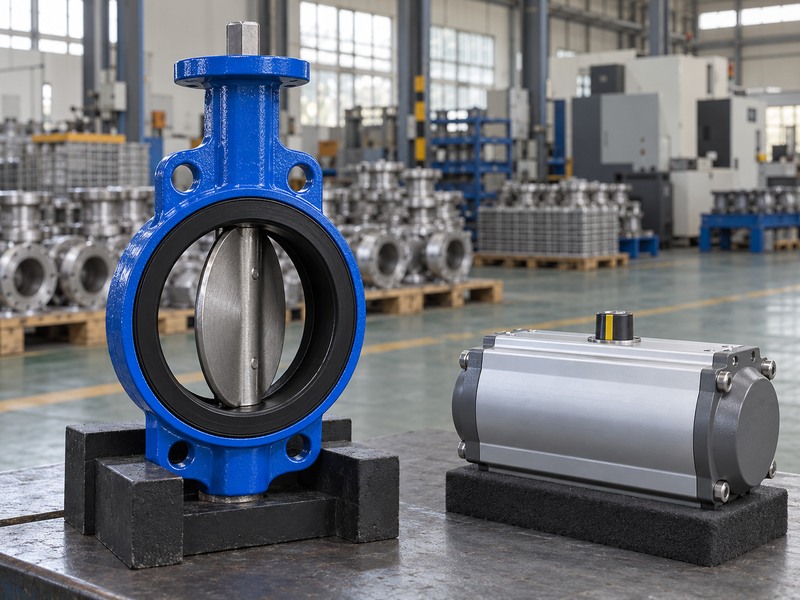
How should you treat the torque data's reference conditions?
Check units and distinguish a required operating torque from a maximum allowable transmitted torque. Record whether the data already includes friction allowances, service corrections or an agreed sizing margin. Adding the same allowance twice can produce unnecessary actuator size, while omitting it can leave inadequate output. For a wafer butterfly valve, confirm that the torque applies to the accepted flange and sealing arrangement; an incorrectly compressed seat can raise resistance and should be corrected rather than hidden by a stronger drive.
- Compare torque at the required travel positions.
- Keep required and allowable torque separate.
- Avoid counting the same service margin twice.
| Torque term | What it describes | Sizing question |
|---|---|---|
| Unseating | Starting motion from the seat | Can the actuator start the stroke? |
| Running | Movement through intermediate travel | Is output sufficient across the curve? |
| Seating | Completing the specified closure | Can it reach the required end condition? |
3. How do you compare two torque curves?
Compare available actuator output with the factored valve requirement at corresponding positions and in the same direction. Check every governing operating case. A high output at the beginning of travel cannot compensate for inadequate output near the end. If only summary values are available, use them as a screening check and ask the suppliers to confirm the complete stroke; three selected points cannot prove that every intermediate position has sufficient margin.
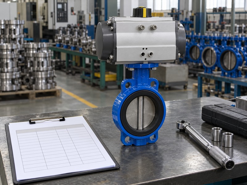
What can an illustrative comparison reveal?
Consider hypothetical valve requirements of 70, 50 and 80 Nm at three reviewed positions. An agreed illustrative factor of 1.25 gives required outputs of 87.5, 62.5 and 100 Nm. An actuator providing 90, 110 and 105 Nm at those positions passes this limited comparison, while one providing only 95 Nm at the final position fails that end check. These are calculation examples, not product ratings or a universal margin recommendation; the actual selection still needs the full curves and mechanical-limit review.
- Use consistent torque units and travel references.
- Apply only the agreed, justified margin.
- Check the full stroke after screening selected points.
| Illustrative position | Valve requirement × 1.25 | Candidate output |
|---|---|---|
| Initial | 70 × 1.25 = 87.5 Nm | 90 Nm: passes this point |
| Intermediate | 50 × 1.25 = 62.5 Nm | 110 Nm: passes this point |
| Final | 80 × 1.25 = 100 Nm | 95 Nm: fails this point |
4. Which air pressure belongs in pneumatic sizing?
Use the minimum available pressure at the actuator during the required stroke, under the specified demand conditions. Compressor discharge pressure or a static regulator reading may not represent that value. Tubing, valves, filters and simultaneous air demand can reduce supply at the actuator. Obtain the output data for the accepted actuator and spring configuration at the governing minimum supply, then confirm that the air system can deliver the required pressure and flow.
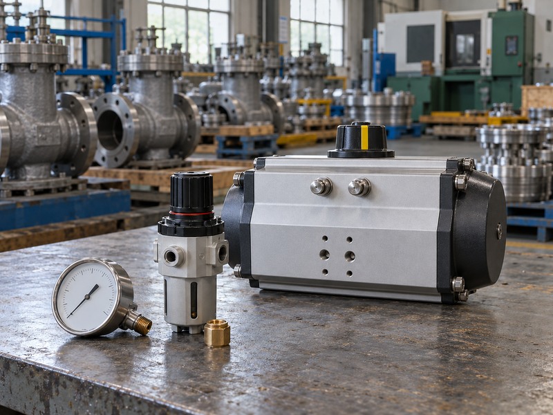
How do speed and air-system restrictions interact?
Check the solenoid valve, tubing, exhaust path and flow controls as part of the package. A restrictive path can slow movement or alter the pressure available during cycling, even if the static gauge looks correct. Do not compensate by assuming a higher supply without reviewing the actuator and valve limits. State the required opening and closing times, then verify them under the accepted operating conditions. The system review should also cover pressure loss after isolation or during the specified air-failure event.
- State minimum dynamic supply at the actuator.
- Review the complete supply and exhaust path.
- Verify timing under the actual package conditions.
| Pressure observation | What it tells you | Remaining issue |
|---|---|---|
| Compressor pressure | Source condition | Distribution losses |
| Static regulator pressure | No-flow local setting | Pressure during movement |
| Minimum actuator supply | Governing drive input | Required output and speed |
5. How do spring-return and double-acting drives differ?
A spring-return drive needs separate air-stroke and spring-stroke checks, while a double-acting drive needs adequate pneumatic output for both commanded directions. Spring loading and mechanism geometry can change available torque through travel. A unit that opens the valve on air does not automatically have enough spring output to complete the required fail stroke. Confirm the selected spring pack, supply condition and fail direction in the actuator sizing record.
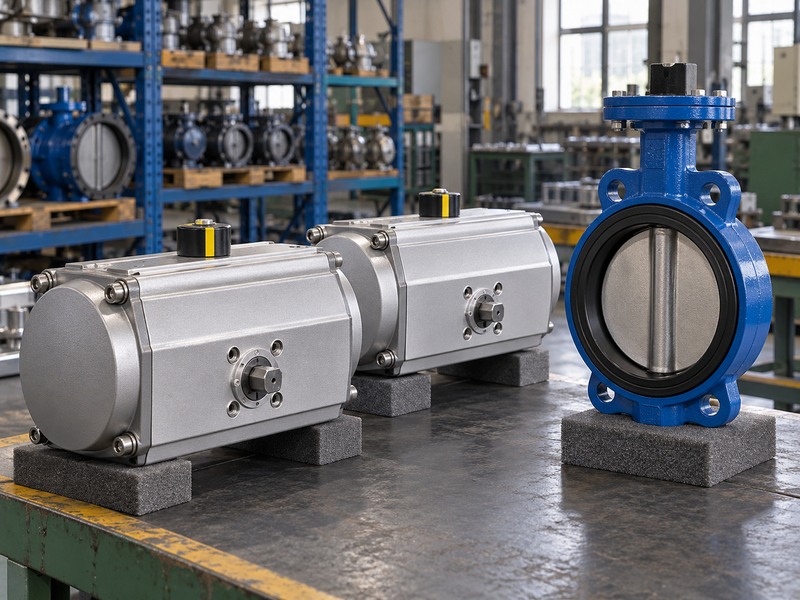
What must the loss-of-energy specification say?
Define the required valve response separately for loss of air, electrical power and control signal. A double-acting actuator usually needs an engineered arrangement if movement after air loss is required. A spring-return package still depends on its mechanical sizing and control arrangement to reach the specified position. For a lug butterfly valve, confirm both the normal duty and the fail-stroke differential pressure rather than assuming the latter is zero when the air supply disappears.
- Check both strokes of the selected spring configuration.
- Define each loss event and required response.
- Use the pressure conditions that can exist during failure.
| Drive arrangement | Output checks | Loss-event question |
|---|---|---|
| Double-acting pneumatic | Both air-powered directions | What happens when air is lost? |
| Spring-return pneumatic | Air and spring strokes | Can the spring complete the required duty? |
| Engineered reserve supply | Specified reserve sequence | What conditions and duration are covered? |
6. Why can an oversized actuator damage the assembly?
An oversized actuator can exceed the allowable transmitted torque of the valve shaft, coupling, bracket or stops. Sufficient minimum output is therefore only half of the mechanical check. Review maximum possible output under the permitted supply range and fault or stall conditions identified by the suppliers. A larger actuator should not be used to force a misaligned coupling, obstructed disc or damaged seat through a problem that requires mechanical correction.
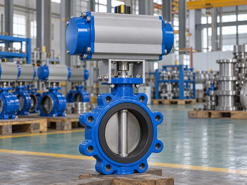
Which components limit the transmitted load?
Obtain the accepted shaft torque limit and the corresponding coupling and mounting limits for the actual assembly. Check how travel stops and actuator protection settings relate to the valve's required seating behavior. Some designs depend on controlled seating torque, while others use a defined travel limit; follow the manufacturer's method. If supply pressure can rise above the sizing basis, include the agreed control or protection arrangement in the package review. Record any required adjustment and verification procedure before commissioning.
- Compare maximum output with all mechanical limits.
- Use the valve's specified stop and seating method.
- Correct interference instead of increasing force.
| Component | Limit to confirm | Potential failure |
|---|---|---|
| Valve shaft | Allowable transmitted torque | Twisting or connection damage |
| Coupling and bracket | Torque and alignment capacity | Slip, distortion or lost motion |
| Stops and protection | Accepted setting method | Overtravel or excessive seating load |
7. Which mounting dimensions must match?
The mounting flange, drive form, engagement length, bracket height and orientation must match the complete assembly drawing. A common mounting designation does not establish every one of those details. Check the stem's square, key or spline geometry and the coupling's usable contact length. A coupling that bottoms on the shaft or carries unintended axial load can create a problem even when the mounting bolts line up cleanly.
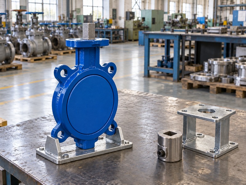
What does ISO5211 establish?
ISO 5211 addresses part-turn actuator attachment interfaces, including specified flange and driving-component dimensions within its scope. It does not replace the review of the complete valve, intermediate support, coupling and service loads. For a flanged butterfly valve package, confirm the selected bracket and operator orientation as well as the interface designation. Include operator weight, reaction loads and maintenance access so dimensional fit does not conceal an unsupported or inaccessible assembly.
- Match drive form, length and mounting reference height.
- Check coupling clearance without unwanted axial loading.
- Review support and access for the complete assembly.
| Interface feature | Check | What it prevents |
|---|---|---|
| Mounting pattern | Accepted flange dimensions | Bolt misalignment |
| Drive engagement | Form, contact length and clearance | Slip or bottoming |
| Bracket and orientation | Loads and access | Distortion or maintenance obstruction |
8. How do you verify the selected package?
Verify the package against the agreed functional and operating checks before accepting it. Confirm actual disc travel, stop settings, direction of movement and position feedback. Where fail action is required, use the accepted test procedure to check the specified event and response. A dry bench demonstration can establish some functions, but it does not automatically prove performance under the maximum service differential pressure or every process condition.
Which records should remain with the valve?
Retain the sizing inputs, valve torque basis, actuator output data, agreed margin, mounting drawing and final settings. Identify the supply conditions and loads used during verification so the record's limits remain visible. Check that a local pointer, limit switch and control-system indication agree with actual valve travel. If the valve, spring pack, solenoid or coupling changes later, review the affected sizing and functional checks before treating the replacement as equivalent to the commissioned package.
- Verify physical travel and feedback together.
- Record test conditions and their limits.
- Reassess changes to the valve, drive or control package.
| Verification | Evidence | Limit to record |
|---|---|---|
| Travel and stops | Observed valve movement | Tested load condition |
| Feedback | Signal agrees with actual position | Signal does not prove shutoff tightness |
| Fail response | Specified event and final position | Covered supply and pressure cases |
9. What should an actuator sizing enquiry contain?
Send the complete valve identification, torque data, service cases, required timing, available supply and loss-event requirements. Include the shaft and mounting drawing, orientation, operator access and any limit on assembly weight or envelope. A torque number without its conditions leaves the actuator supplier to guess which duty it represents. Keep unresolved assumptions in the quotation so they can be reviewed before a specific actuator and spring configuration are accepted.
How should the supplier return the selection?
Ask for a comparison of required and available torque, the selected configuration, mechanical-limit checks and declared deviations. For RUITO enquiries, contact us with the valve duty and supply conditions so engineering can coordinate the valve, drive and mounting review. Keep the accepted calculation and assembly drawing with the order. Before release, confirm that the delivered actuator and accessories match the approved configuration and that the required settings and verification records will accompany the package.
- Send duty, torque and supply data together.
- Request both normal and fail-stroke comparisons.
- Retain configuration and settings under revision control.
| Enquiry field | Required detail | Supplier confirmation |
|---|---|---|
| Valve duty | Torque basis and service cases | Factored demand by stroke |
| Actuator supply | Minimum and maximum permitted input | Available output and protection |
| Assembly | Mounting, access and fail action | Complete accepted configuration |
10. What questions arise during butterfly actuator sizing?
Q1. Can I choose an actuator from valve DN alone?
No. Torque depends on the exact valve, seat and operating conditions. Obtain the required torque by travel and compare it with actuator output at the governing supply conditions.
Q2. What's the best safety factor for every butterfly valve?
There is no single factor to apply without reviewing the basis. Agree the margin with the valve and actuator suppliers, account for the actual service, and check whether supplied torque data already includes allowances.
Q3. How do I know whether a spring-return actuator will close?
Compare its spring-stroke output with the required closing torque throughout travel under the specified fail-event conditions. Passing the air-powered opening check does not establish adequate spring closure.
Q4. Can I increase air pressure when the valve feels tight?
Investigate the cause before changing supply. Disc interference, seat compression or coupling misalignment needs correction. Any supply change must remain within the accepted actuator, shaft and mounting limits.
Q5. Can position feedback prove the valve is leak-tight?
No. Feedback reports the checked position or travel condition. Shutoff performance requires the agreed closure design and inspection evidence; a limit-switch signal does not measure leakage.