
Avoid manual butterfly valve symbol errors by reading the project legend, operator notation and valve tag together. A small symbol can identify the valve function while leaving its body connection, materials and pressure rating to other documents. Confirm those details before turning a drawing mark into a purchase description.
1. How do you read a manual butterfly valve symbol?
Read a manual butterfly valve symbol from the drawing's approved legend and referenced drafting convention, then confirm the operator and tag. Do not identify the complete assembly from a familiar shape alone. Different document systems can represent the valve body and manual operating method with different levels of detail.

Which document establishes the symbol's meaning?
Start with the legend belonging to the actual project and drawing revision. Check any referenced standard within its stated scope, rather than importing a symbol from an unrelated plant or software library. For example, ISO 10628-2 addresses graphical symbols for chemical and petrochemical diagrams; its scope is different from an electrical connection drawing. The selected project may apply that standard together with its own approved legend and documentation rules.
Follow the valve tag into the schedule or data sheet for details the symbol does not carry. If the legend and schedule disagree, resolve the discrepancy before ordering or changing equipment. Keep the accepted interpretation in the project record so later readers do not repeat the same assumption.
- Use the actual project's legend and revision.
- Check the referenced convention's scope.
- Follow the tag to the valve schedule.
| Document | What to confirm |
|---|---|
| Legend | Meaning of the drawing mark |
| Operator notation | Manual or other actuation method |
| Valve schedule | Specified assembly and duty |
2. How can you distinguish butterfly and other valve marks?
Distinguish a manual butterfly valve symbol by its legend entry and associated operator information, rather than assuming every circular or crossed shape means the same valve. Ball, gate, globe and butterfly symbols can share nearby lines or similar outlines. Small graphical differences matter only within the convention that defines them.
What does an official example demonstrate?
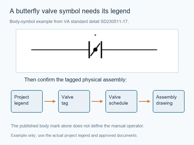
The US Department of Veterans Affairs publishes a valve-symbol standard detail with separately labeled butterfly, ball, gate and control-valve entries. Its butterfly-body example uses a short diagonal mark on the horizontal flow line between boundary lines, rather than a universal circle-and-diagonal formula. The sheet labels that entry as a butterfly valve, so its exact project use and manual operating notation still need the applicable legend and schedule. Use the example to understand why visual recognition must be checked against a named source.
Do not combine a body mark from one library with an operator mark from another without approval. A correct-looking hybrid can carry an unintended meaning in the final drawing. Keep the selected symbol definition consistent throughout the issued document set.
- Compare named legend entries.
- Avoid universal shape assumptions.
- Do not mix unapproved symbol libraries.
| Drawing observation | Required check |
|---|---|
| Similar body marks | Exact legend entry |
| Added operator feature | Approved actuation notation |
| Different software library | Project symbol definition |
3. How is manual operation shown?
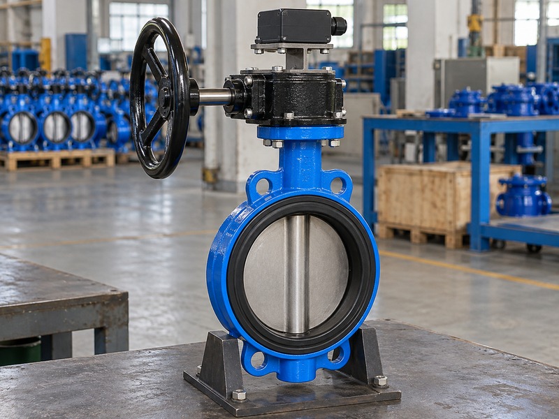
A manual butterfly valve symbol should identify manual operation through the project's approved operator mark, annotation or linked schedule. A handwheel-shaped feature alone does not identify the internal valve type. Gate and globe valves can also use wheels, while a butterfly valve may use either a lever or a geared handwheel.

Why should the operator and body be read separately?
The valve-body mark describes the selected valve function under the drawing convention. The operator information describes how the assembly moves. A geared handwheel remains manual even though it uses several input turns for a quarter-turn output. The physical outline and operating envelope belong on the assembly or installation drawing rather than being inferred from the schematic.
A manual butterfly valve symbol enquiry should therefore include the required lever or gearbox arrangement alongside the selected body configuration. If a supplier changes the operator, review torque, access and the project document update together. Do not infer automatic closure, remote operation or a specific failure response from a manual wheel mark that contains none of those instructions.
- Read body and actuation information separately.
- Confirm lever or geared-wheel requirements.
- Use the assembly drawing for physical dimensions.
| Information | Where to confirm it |
|---|---|
| Valve type | Legend and schedule |
| Manual operator | Approved mark or annotation |
| Physical envelope | Selected assembly drawing |
4. How does the valve tag connect the documents?
The tag beside a manual butterfly valve symbol connects the schematic location with the valve schedule, data sheet and supplied item under the project's identification rules. Read the complete tag and document revision. A symbol without that connection can leave purchasing or maintenance with an incomplete description of the required assembly.
What should you trace before issuing an enquiry?
Follow the tag to the selected duty and specification fields, including size, connection, materials, operating limits and manual operator. Check whether any notes or exceptions apply to that item. The same symbol can appear on several branches that require different materials or pressure-temperature conditions. A document map can show the path from legend and symbol to tag, schedule and assembly drawing, but the actual project defines the identifiers.
Do not invent a tag prefix as a universal code for every manual butterfly valve. If a revision changes an item, keep its cross-references consistent so procurement and site personnel can identify the correct version. Resolve missing or duplicate tags through the project's document-control process before treating the schedule as an order list.
- Trace the complete tag.
- Check item notes and revision.
- Resolve missing or conflicting references.
| Cross-reference | Purpose |
|---|---|
| Legend to symbol | Identify the represented function |
| Tag to schedule | Find duty and configuration |
| Schedule to assembly | Confirm the supplied physical arrangement |
5. What cannot the symbol tell you by itself?
A manual butterfly valve symbol alone usually does not provide every material, dimensional, pressure-temperature or sealing requirement needed to buy a valve. Use the applicable schedule, data sheet and assembly drawing. The project's drafting rules determine which additional details appear directly on the schematic.

Which assumptions can create an incorrect order?
Do not infer wafer, lug or double-flanged construction from a generic body mark unless the project explicitly encodes that information. The same caution applies to seat material, flange drilling, face-to-face length and end-of-line capability. A manual butterfly valve symbol used for an item requiring threaded lugs still needs the actual approved interface and duty. The handwheel does not raise the valve's pressure rating or establish chemical compatibility.
A pressure-test value also belongs in its correct inspection context rather than being copied into the operating field. Ask for a complete item data sheet when essential order details are missing. This lets suppliers quote one defined assembly and identify deviations instead of guessing from the drawing mark.
- Confirm body connection and materials separately.
- Use model-specific operating and sealing limits.
- Request missing order fields before quotation.
| Missing field | Required source |
|---|---|
| Materials and seat | Approved data sheet or parts list |
| Connection and dimensions | Interface and assembly drawing |
| Operating limits | Selected model rating information |
6. How should position feedback appear in the records?
When a manual butterfly valve symbol represents an assembly with position feedback, the project documents must distinguish the manual operating method from the monitoring signals. A limit switch does not provide actuation torque. Its signal definitions, electrical connections and system use need the appropriate control and electrical documents.
Why should you avoid treating one diagram as every diagram?
A process schematic can identify that feedback exists without showing terminal numbers, contact ratings or field wiring. Those details belong in the selected accessory data and approved electrical documentation. ISO 10628-2's graphical-symbol scope does not cover electrotechnical symbols, so it should not be treated as a complete wiring instruction. Confirm the valve's open and closed signal meanings in the input-output schedule and functional description.
A manual butterfly valve symbol with feedback still represents local manual movement unless another approved operating arrangement is specified. Mechanical position indication does not prove seat tightness. Keep the feedback commissioning record separate from the required valve leakage acceptance and follow the project-defined response when a signal is unavailable or inconsistent.
- Separate manual actuation and monitoring.
- Use actual accessory and wiring documents.
- Distinguish position feedback from sealing evidence.
| Record | Information |
|---|---|
| Process schematic | Valve function and required feedback |
| Electrical documents | Device connections and circuit details |
| Functional description | Meaning and use of each signal |
7. How do normal position and failure response differ?
For a manual butterfly valve symbol, a stated normal operating position describes an intended process condition, while a failure-response requirement describes what the system must do under a defined event. The two are different specification fields. An ordinary local manual assembly does not move automatically merely because a drawing marks it normally closed.

Which notes need a process or controls review?
Read position notes, locks and operating restrictions under the project's defined terminology. Ask what event any stated failure position refers to and which equipment performs the movement. A manual lever or gearbox may remain where the operator leaves it within its approved holding design, but that is not an automatic protective action. If the project requires spring action, powered shutdown or another special response, identify the exact assembly and validation requirements separately.
Do not add a failure-position abbreviation based on a generic valve catalogue. Confirm the required behavior with the responsible process and controls teams. Keep the resulting note, data sheet and operator specification aligned before procurement, then verify the installed arrangement through the approved commissioning procedure.
- Define normal operating position.
- Identify any required event response.
- Confirm which assembly performs the action.
| Position term | Question to answer |
|---|---|
| Normal position | What process condition is intended? |
| Locked position | What restraint and procedure apply? |
| Failure response | What event and operating mechanism are specified? |
8. What should change after an operator conversion?
Review a manual butterfly valve symbol and its linked records whenever an approved conversion changes the operating method, feedback or item specification. A lever-to-gearbox change can affect access and assembly details even when the process function stays the same. A manual-to-powered change can also affect controls and failure-response information.

How do you keep the installed arrangement traceable?
Use the project's change-control process to identify which drawing, schedule, data sheet and maintenance records need revision. The exact scope depends on the conversion and drafting rules. Do not redraw the process symbol alone while leaving the operator and accessory details unchanged elsewhere. Compare the new torque, mounting and installation envelope with the actual valve and site.
Record the approved parts and functional checks after installation. If the symbol remains valid under the project convention, retain it with the revised linked description rather than inventing a new mark. The aim is a consistent document set that identifies the installed hardware and operating task without requiring maintenance personnel to infer the change from a photograph.
- Review all affected document references.
- Record the new physical assembly.
- Retain approved change and commissioning evidence.
| Changed feature | Records to review |
|---|---|
| Lever or gearbox | Operator and envelope details |
| Powered actuation | Controls and required response |
| Feedback accessory | Signals, wiring and functional checks |
9. How do you turn the schematic into a complete enquiry?
Convert a manual butterfly valve symbol into an enquiry by collecting the tagged item's duty, configuration, interfaces, operator and acceptance requirements. Provide the relevant legend and schedule extracts together. A supplier should receive a defined technical requirement rather than a cropped symbol with an assumed universal meaning.

What should purchasing ask the supplier to confirm?
Ask for a complete selected assembly drawing, material arrangement and permitted operating limits for the stated fluid. Confirm flange compatibility, disc clearance, manual effort and required inspection records. Include any feedback accessory and its exact documentation scope. RUITO's documented valve configurations remain subject to their own material, size and duty boundaries, so a general symbol cannot expand the available service range.
Require the offer to list deviations and missing inputs before manufacture. Match the accepted item tag with the supplied assembly and required records at dispatch. Retain the final project documents and installation information together so a future replacement enquiry can identify the same configuration without reconstructing it from an old schematic alone.
- Supply legend, tag and duty information together.
- Request explicit deviations and missing inputs.
- Match the accepted item with the shipped assembly.
| Enquiry field | Supplier confirmation |
|---|---|
| Fluid and duty | Suitable selected configuration |
| Interfaces and operator | Approved physical assembly |
| Acceptance | Required inspection and documentation |
10. What do readers ask about manual butterfly valve symbols?

Q1. Is there one universal manual butterfly valve symbol?
Use the project's approved legend and referenced convention. Body and operator notation can vary across drawing systems.
Q2. Does a handwheel mark mean the valve is a gate valve?
No. Several valve types can use handwheels, including geared butterfly valves. Read the body mark and operator information separately.
Q3. Can I identify wafer or lug construction from any butterfly mark?
Only when the project's notation explicitly provides that information. Otherwise, confirm the tagged item in the schedule and interface drawing.
Q4. Does normally closed mean it closes automatically on failure?
No. Confirm the defined event, operating mechanism and required response separately from the normal process position.
Q5. What is the best way to resolve a symbol and schedule mismatch?
Ask the responsible project team to issue a consistent approved interpretation and revision before ordering or changing the equipment.
Send the legend extract, valve tag, schedule and operating duty when you contact us. RUITO can review the physical configuration and identify the missing information needed for a complete valve enquiry.