
Avoid manual wafer butterfly valve installation mistakes by checking the actual pipe interfaces, disc opening envelope and seat-sealing instructions before tightening the joint. A compact body can fit between two flanges while its disc still strikes the adjoining bore. Verify the complete installed assembly, including its lever or geared handwheel.
1. What identifies a manual wafer butterfly valve?
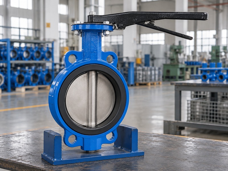
A manual wafer butterfly valve uses a compact wafer body clamped between the selected pipe flanges and a local lever or geared handwheel for operation. The body may have alignment features, but its installation depends on the approved through-bolting arrangement. It should not be confused with a threaded-lug or double-flanged body.
Which features belong on the assembly drawing?
Identify the wafer body, sealing design, disc, stem and complete manual operator. Show the flange compatibility, face-to-face length and actual opening envelope. A few alignment ears do not turn a wafer body into a lug valve with independent threaded connections. Likewise, the use of a handwheel does not establish a different pressure boundary or a higher service rating.
Keep connection style and operating method as separate specification fields. For RUITO's documented conventional wafer configurations, size, materials and duty limits apply to the selected assembly rather than every product described as a butterfly valve. Request the approved interface drawing before buying fasteners or planning a replacement, so the site works from the supplied configuration.
- Identify body style and operator separately.
- Request the selected interface drawing.
- Avoid substituting a lug connection assumption.
| Feature | Meaning |
|---|---|
| Wafer body | Clamped between selected pipe flanges |
| Alignment ears | Positioning features within the design |
| Manual operator | Local lever or geared-wheel input |
2. Which service conditions should you confirm?
Select a manual wafer butterfly valve for the actual fluid, temperature, operating pressure and closing differential pressure. The wafer connection alone does not establish suitability for water, oil, gas or chemical liquid. The seat, disc, stem and pressure body need a compatible, model-specific configuration.
How do you avoid transferring limits between applications?
Provide the fluid composition, additives and cleaning conditions before choosing materials. A conventional EPDM water-seat arrangement should not be relabeled for oil service because the same body size is available. Clean-gas or lined chemical configurations require their own materials and acceptance requirements. Drinking-water applications need the actual approval scope for the selected contact materials and temperature.
Include normal duty and the maximum values that can occur together, rather than combining separate catalogue maxima. The manual operator also needs torque sizing at the stated differential pressure and enough access for the user. If the duty includes solids or deposits, describe them so engineering can assess obstruction, wear and the need for another valve arrangement.
- Provide complete fluid and cleaning details.
- Use simultaneous temperature-pressure limits.
- Size the operator for the selected duty.
| Input | Review |
|---|---|
| Fluid and additives | Materials and sealing compatibility |
| Closing differential | Seat and operator demand |
| Solids or deposits | Obstruction and wear conditions |
3. How should the pipe flanges and body length match?
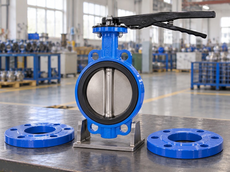
A manual wafer butterfly valve must match the selected pipe-flange standard, facing and actual installation space. Confirm its face-to-face dimension from the approved drawing. Nominal pipe size and a visually similar bolt circle do not establish that a replacement has the correct interface or disc clearance.
Which dimensional assumptions should you remove?
Compare the proposed valve with the actual flange details and the space between the finished mating faces. RUITO's documented conventional wafer arrangement uses its specified EN 558 series-20 length basis, but another design may use a different approved route. Do not apply one length to every wafer butterfly valve without checking the model. A manual wafer butterfly valve replacement should also account for pipe lining, flange facing and the selected seal arrangement.
Do not pull misaligned pipes together using the valve fasteners. Resolve the pipe position and joint geometry before completing installation. If a reducer, dismantling joint or equipment nozzle sits next to the valve, include that component in the drawing comparison instead of checking only the two nominal pipe sizes.
- Use the approved face-to-face value.
- Compare complete flange specifications.
- Resolve pipe alignment before tightening.
| Interface item | Check |
|---|---|
| Flange standard and facing | Compatibility with the selected valve |
| Body length | Approved face-to-face basis |
| Adjoining component | Actual bore and installation geometry |
4. How do you check disc opening clearance?
Check a manual wafer butterfly valve's full disc movement against the actual adjoining pipe bore and nearby components. The disc can project beyond the valve faces as it opens. Its approved three-dimensional envelope must clear the pipe, lining, reducer or equipment connection through the required travel.
Why is a nominal-size comparison insufficient?
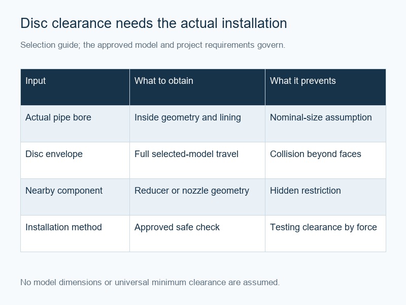
Pipe wall thickness and lining can reduce the clear internal diameter while leaving the nominal size unchanged. A flange or nozzle can also present an obstruction close to the valve face. Use the selected valve's opening-envelope information and actual adjacent geometry for the review. A simple comparison table can identify the required inputs, but it cannot replace the approved installation drawing or a controlled clearance check.
Keep the disc within the manufacturer's prescribed position during valve insertion and centering. Do not rotate it into a suspected obstruction or use extra lever force to test whether it clears. If the required envelope is unavailable, obtain it from the supplier before final assembly, especially when replacing a different body or sealing design.
- Check actual bore, lining and nearby restrictions.
- Use the full disc envelope.
- Avoid force as a clearance test.
| Clearance input | Reason |
|---|---|
| Actual pipe bore | Available opening space |
| Disc envelope | Movement beyond body faces |
| Nearby geometry | Reducer, nozzle or lining interference |
5. Does the valve need separate flange gaskets?
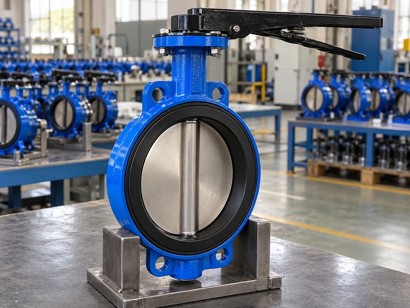
Use the gasket or integral sealing arrangement specified for the selected manual wafer butterfly valve. Some resilient-seat designs seal at the flange faces through their own liner arrangement, while other constructions have different requirements. A universal instruction to add gaskets or omit them can damage the wrong assembly.
What should the installation instructions clarify?
Confirm the mating-face condition, sealing contact area and any restrictions for gaskets, lubricants or joint materials. Extra gaskets can change compression or interfere with a design that relies on its own seat faces. A construction requiring a separate gasket needs the specified geometry and compatible material. Do not transfer the rule from another manufacturer's or another seat design's manual.
For a manual wafer butterfly valve water-service package, keep the approved seal arrangement with the item and piping joint specification. Inspect the seat faces for transport damage or contamination before installation. If the supplied valve differs from the approved drawing, resolve that discrepancy before tightening rather than improvising a sealing stack to compensate for the difference.
- Follow the actual seat and joint design.
- Check mating faces and contact area.
- Resolve differences before assembly.
| Joint question | Approval source |
|---|---|
| Separate gasket required? | Selected valve installation instructions |
| Allowed joint material? | Fluid and seal compatibility review |
| Face condition acceptable? | Specified inspection criteria |
6. How should you select and tighten the through bolts?
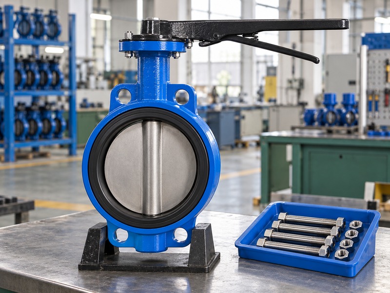
Select a manual wafer butterfly valve's through bolts for the actual flange joint and approved installation procedure. Confirm diameter, length, material, washers where specified and tightening requirements. The bolt kit must clamp the selected assembly correctly without interfering with the valve body, operator or full disc movement.
Which site practices can distort the assembly?
A wrong joint stack or uneven tightening can alter the seat's fit or create mechanical interference. Center the valve and follow the prescribed disc position and tightening sequence for that model. Use the specified torque values and method rather than copying a generic table without checking its applicability. The pipe supports should maintain alignment without forcing the wafer body into a strained position.
Check access for the fasteners before finalizing the operator orientation and nearby supports. If a bolt fouls the body or another component, review the approved length and joint arrangement instead of grinding the casting or removing a required part. Retain the selected bolting schedule with the installation record so later replacements use the same controlled basis.
- Use the actual joint stack and bolt schedule.
- Follow model-specific centering and tightening.
- Do not modify the body to clear a wrong fastener.
| Bolting item | Review |
|---|---|
| Length and diameter | Fit of the complete joint |
| Material and washers | Specified joint requirements |
| Sequence and torque | Controlled clamping and seat fit |
7. What space does the manual operator need?
A manual wafer butterfly valve needs usable space around its lever or handwheel as well as clearance inside the pipe. Check the complete operating sweep and the user's standing position. A body that fits a narrow pipe gap can still leave an inaccessible or obstructed manual operator.
How do lever and gearbox layouts differ?
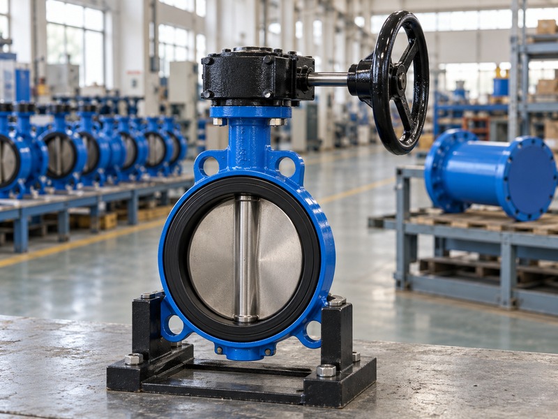
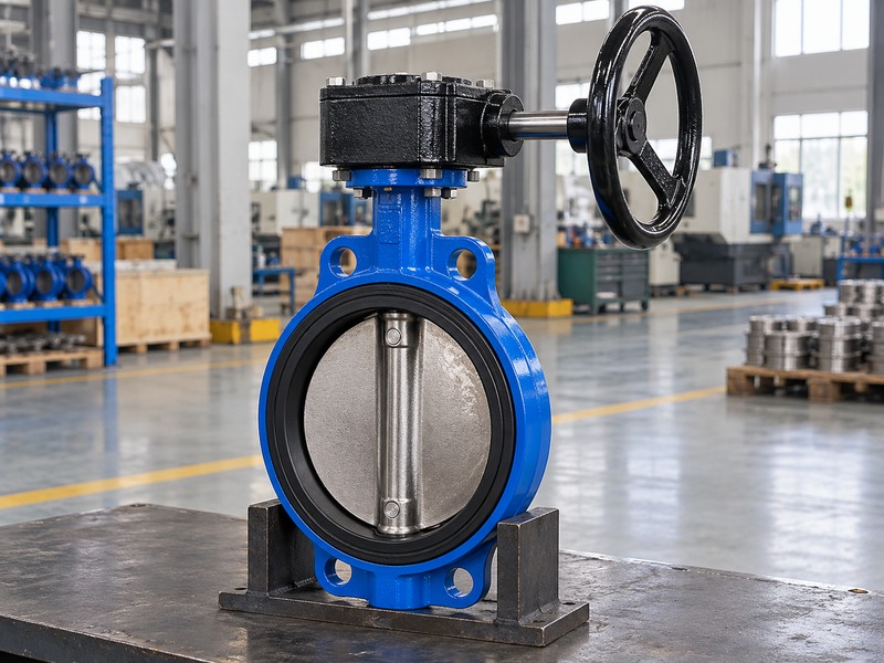
A direct lever needs a clear arc through its approved travel and access to its holding mechanism. A geared wheel needs rim and grip clearance, along with space for the gearbox and any planned maintenance. The operator torque and permitted input must match the selected valve and service. A manual wafer butterfly valve fitted to a compact equipment package should be checked with final insulation, supports and nearby services in place.
Do not rotate or replace the operator merely to clear an obstruction without reviewing coupling engagement and disc correspondence. Ask for a revised assembly drawing when its orientation changes. Include removal space where the maintenance procedure requires it, so the installed valve remains serviceable after the equipment is complete.
- Check lever sweep or wheel grip space.
- Use final surrounding equipment geometry.
- Approve operator changes and maintenance access.
| Operator | Space to review |
|---|---|
| Lever | Travel arc and locking access |
| Handwheel | Rim, grip and gearbox envelope |
| Both | Safe standing and maintenance position |
8. What if the valve becomes stiff after installation?
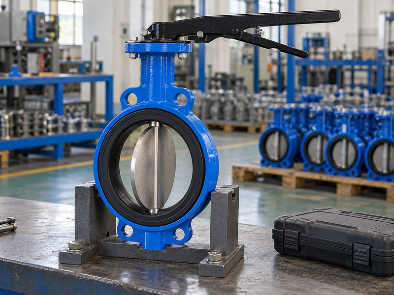
If a manual wafer butterfly valve becomes stiff after installation, stop forcing it and compare the installed joint with the approved arrangement. Disc interference, pipe misalignment or altered seat compression can increase effort. Service differential pressure and internal condition also need review before assuming that the manual operator is undersized.
Which observations separate installation and service causes?
Record whether the valve moved correctly before fitting and where resistance appears afterward. Check the actual joint components, tightening record and nearby bore geometry under the approved isolated inspection procedure. A change that appears only after final clamping can point toward a joint or alignment issue, but it is not a diagnosis by itself. Do not loosen a pressurized flange or remove the operator to test a theory.
Provide the supplier with the installation drawing, photographs and service conditions. Keep any leakage finding separate from the operating-effort report so both receive the right acceptance checks. After corrective work, repeat the relevant mechanical and pressure or leakage inspections before returning the assembly to the system's operating procedure.
- Record before-and-after installation behavior.
- Compare the actual joint with approval.
- Recheck after corrective work.
| Observation | Review area |
|---|---|
| Stiff after clamping | Joint stack, alignment and seat fit |
| Stops at one point | Disc clearance and obstruction |
| Effort changes in service | Duty and internal condition |
9. What should final acceptance and the order include?
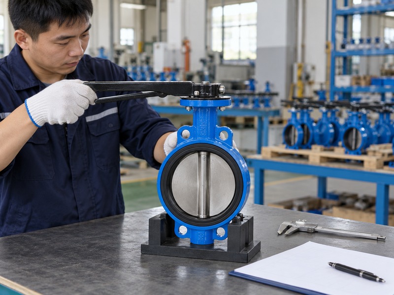
A manual wafer butterfly valve order should define duty, materials, flange compatibility, disc clearance information, manual operator and inspection scope. Final acceptance must compare the actual supplied assembly with that approval. Mechanical movement, interface dimensions and the specified pressure or leakage tests provide different evidence.
How do you retain a useful installation record?
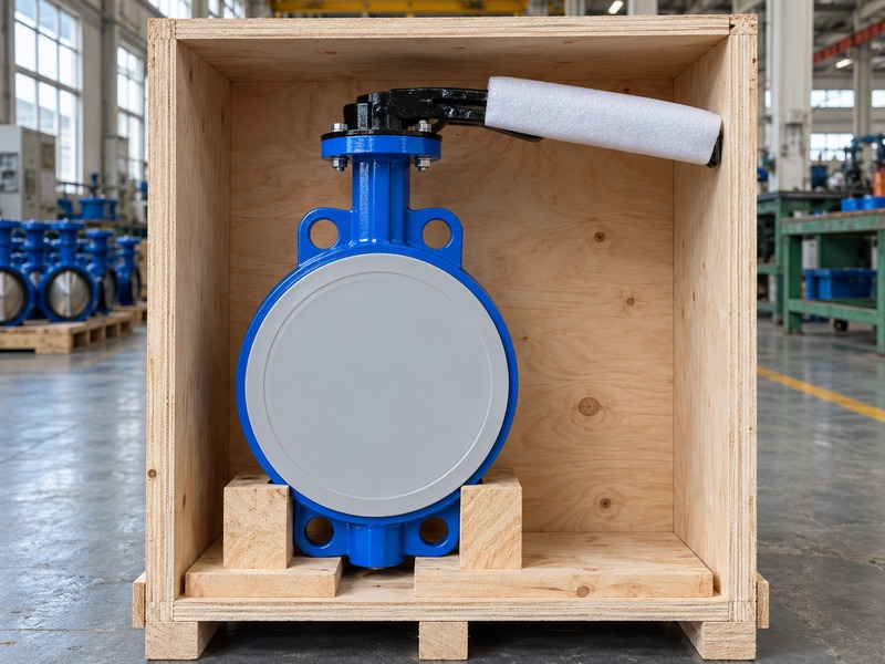
Keep the valve and operator identification, approved drawing revision, joint details and required test records together. Note any accepted deviations and their effect on installation or maintenance. A smooth movement check cannot replace a required seat-leakage test, and a pressure-test certificate cannot prove the external operator clears a wall. Check the seat, disc and body for damage before packing or installation.
Protect both flow faces and support the body without loading the lever or wheel during handling. RUITO can review the selected configuration and provide the relevant assembly and inspection information for the agreed scope. Retain the final installed arrangement for future replacement orders so maintenance does not depend on a generic wafer-valve description.
- Keep duty and assembly approval together.
- Distinguish interface, function and sealing evidence.
- Retain the final installed configuration.
| Acceptance item | Evidence |
|---|---|
| Interface | Approved drawing and dimensional checks |
| Manual function | Travel, effort basis and indication |
| Pressure and sealing | Specified test record and criterion |
10. What do installers ask about manual wafer valves?
Q1. Can I always add a gasket to improve sealing?
No. Follow the selected valve's sealing-face instructions. An extra gasket can alter a resilient-seat arrangement that relies on its own liner faces.
Q2. Does matching DN prove the disc will clear the pipe?
No. Use the actual pipe bore, lining and nearby geometry with the approved opening envelope.
Q3. Can I use a wafer valve as an unsupported end valve?
Only when the exact design has explicit approval for that condition. A conventional wafer clamping arrangement should not be assumed suitable.
Q4. What should I do if the handle becomes stiff after tightening?
Stop and investigate the installed joint, clearance, alignment and service conditions through the approved safe procedure. Do not add force or loosen a pressurized flange.
Q5. Can I replace the lever with a wheel to fix interference?
Review a complete approved operator conversion first. Torque, stem fit, mounting, travel and the new wheel envelope must all match the valve and installation.
Send the pipe-flange details, adjoining bore information and operating duty when you contact us. RUITO can review the wafer interface, manual operator and inspection information needed before installation.