
Fix manual butterfly valve with limit switch feedback mistakes by comparing actual disc travel, the monitoring connection and the approved signal logic. An operator still moves this assembly by hand. The switch reports a defined position; it does not supply operating torque, confirm seat tightness or provide automatic closure by itself.
1. What is a manual butterfly valve with limit switch?
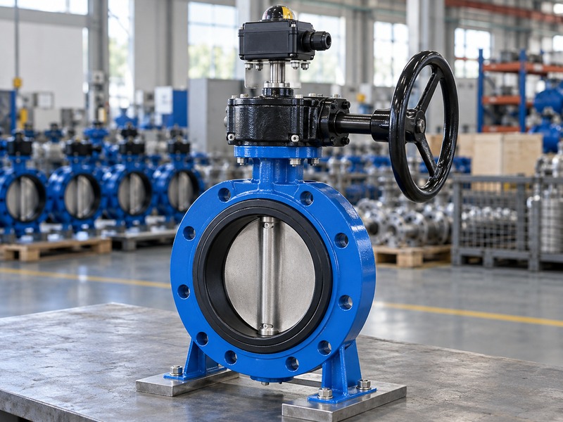
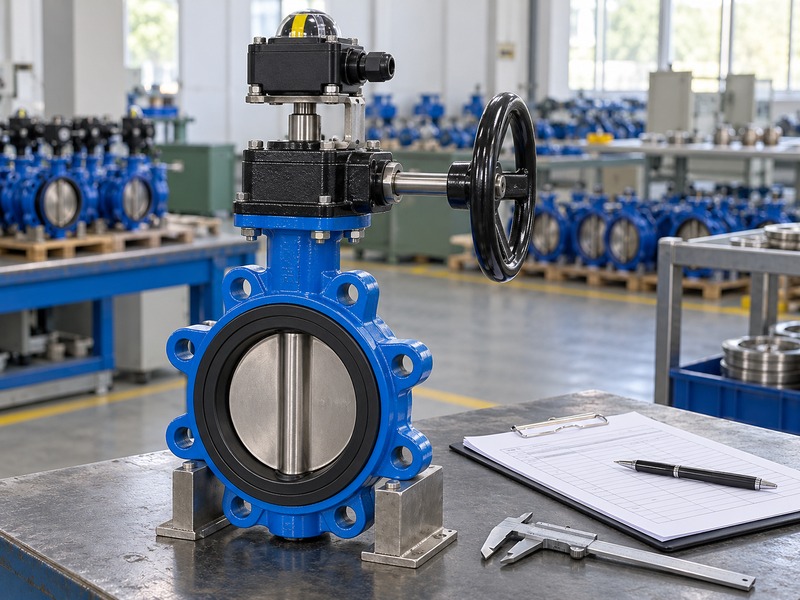
A manual butterfly valve with limit switch combines local mechanical operation with one or more position-dependent electrical signals. A cam, target or other approved mechanism changes the switch output as the valve moves. The signal represents the monitored position within the assembly's defined switching range.
Which functions should you keep separate?
The valve body and seat control the fluid boundary, the lever or gearbox supplies mechanical movement, and the switch reports the selected position. Each function has its own specification and acceptance checks. A control panel may use the signal to display status or support an interlock, but the complete system design determines what that input permits. Do not describe a position switch as an actuator or a leakage detector.
A mechanically closed indication can remain present while a damaged seat leaks. Likewise, an electrical fault can remove the signal while the disc stays still. Define the required mechanical position and signal meaning before choosing the switch package, so purchasing, controls and commissioning teams work from the same description.
- Separate movement, position feedback and sealing.
- Define what each signal means.
- Record the monitored switching range.
| Function | Responsible component |
|---|---|
| Flow isolation | Valve disc and seat |
| Manual movement | Lever or geared handwheel |
| Position feedback | Approved switch mechanism |
2. When is position feedback useful?
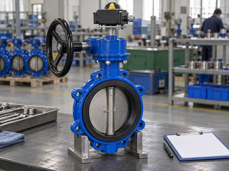
A manual butterfly valve with limit switch is useful when a remote operator or control system needs to know the local valve's position. It can reduce reliance on an occasional visual check. Its value depends on correctly mounted feedback, defined logic and a commissioning record that connects the signal with actual movement.
What should the process requirement state?
Identify whether the system needs open indication, closed indication or both. Describe how the control system uses each input, including what happens during movement or when feedback is unavailable. A simple status display and a safety-related interlock have different design responsibilities. The switch assembly alone does not establish the suitability of the whole protective function.
Keep any required independent isolation or leakage verification in the operating procedure. If the valve is difficult to access, consider whether position monitoring solves the actual task or whether remote actuation is also needed. A person must still reach and operate a manual assembly, even when its position appears on a distant screen. Agree that operating strategy before specifying the accessory.
- Define open and closed indication needs.
- State the control system's use of each input.
- Check whether remote actuation is also required.
| Need | What to specify |
|---|---|
| Status display | Signal meaning and availability |
| Interlock input | Approved project logic and validation |
| Remote operation | Separate actuator and control requirements |
3. Where should the feedback mechanism connect?
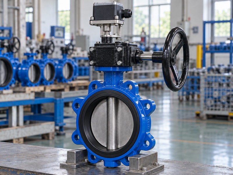
The feedback mechanism on a manual butterfly valve with limit switch must follow the approved valve or operator output movement. Its mounting and coupling should maintain that relationship through the full stroke. A switch fitted to an unsuitable moving part can report motion without accurately representing the disc position.
Why does a gearbox need particular attention?
A geared handwheel can turn many times while the valve stem moves through a quarter turn. The raw wheel input is therefore different from the operator output. Use the selected manufacturer's approved monitoring interface, coupling and bracket rather than assuming any rotating shaft can drive the switch box. Check the bracket stiffness, engagement and clearance from the wheel or lever.
A manual butterfly valve with limit switch assembly should show the feedback arrangement on the complete drawing. If a coupling slips, the switch and visible indicator may move together while the disc does not follow. Keep actual disc correspondence as a separate commissioning check, and include the mounting parts in the controlled spare-parts information.
- Use the approved monitoring interface.
- Distinguish gearbox input and output travel.
- Check coupling retention and bracket stiffness.
| Mechanical item | Check |
|---|---|
| Feedback drive | Correspondence with valve output |
| Bracket | Stiffness and clearance |
| Coupling | Engagement and retention |
4. How should open and closed signals be defined?
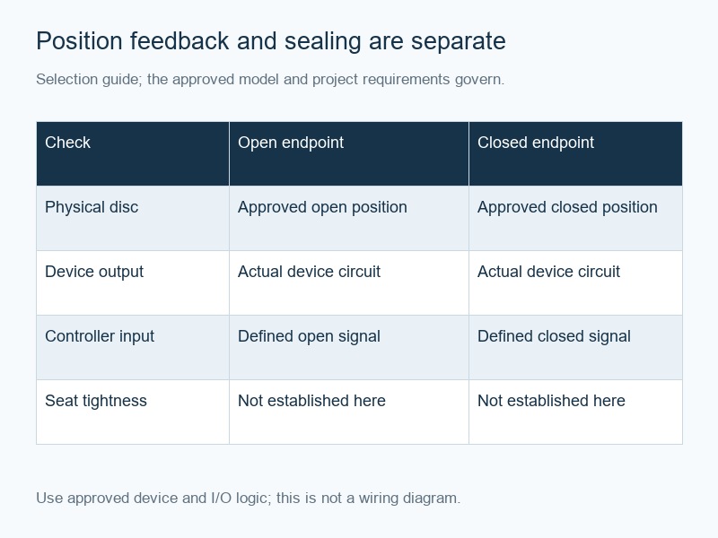
Define the signals of a manual butterfly valve with limit switch in an approved input-output schedule and functional description. State which mechanical position activates each system input. Contact labels such as normally open or normally closed describe a device condition and cannot replace the complete project's signal logic.
What should the logic record include?
Document the expected inputs at the approved open endpoint, closed endpoint and intermediate travel. Specify how the system interprets unavailable or inconsistent feedback. A conceptual two-endpoint table can explain the intended states, but it is not a universal wiring diagram. Actual cams, contact arrangements, sensor types and input circuits can produce different electrical conditions.
In particular, an inactive signal might indicate intermediate travel, a disconnected wire, missing sensor power or another fault. The controls design must distinguish the conditions it needs to detect. Keep the physical valve position, device contact condition and controller interpretation in separate fields. This makes commissioning clearer and prevents maintenance staff from changing a contact merely to make a screen display the expected word.
- Define endpoint and intermediate states.
- Document loss-of-signal behavior.
- Use the actual device and controller diagrams.
| Record field | Required meaning |
|---|---|
| Mechanical position | Approved endpoint or travel range |
| Device output | Actual contact or sensor condition |
| System interpretation | Display, alarm or permitted action |
5. Which electrical details must match the control system?
A manual butterfly valve with limit switch needs an electrical interface compatible with the selected monitoring input. Confirm the switch or sensor type, supply requirements where applicable, contact load rating and connection diagram. A dry contact and a powered proximity sensor cannot be treated as interchangeable outputs.
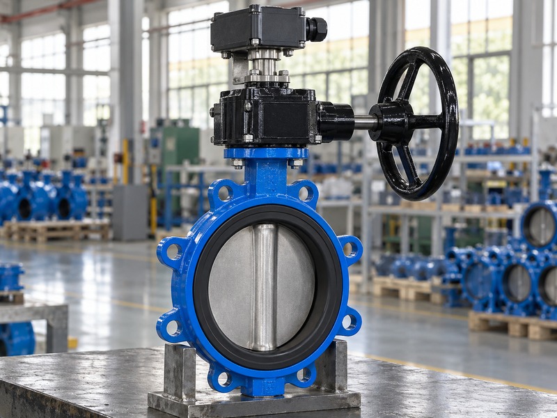
What should you ask before ordering the switch box?
Provide the control-system input type and the intended circuit conditions to the responsible electrical designer. Ask the supplier for the exact accessory data sheet, terminal identification and approved wiring diagram. Check AC and DC ratings independently where the device distinguishes them. A contact rating does not establish that every control load or input circuit is suitable.
Also confirm cable entry, conductor termination and any required isolation or protection in the project design. Do not copy terminal numbers from another box that looks similar. If the accessory changes during supply, review its electrical and mechanical interfaces before acceptance. The final wiring and commissioning work should follow the actual device instructions and the site's authorized electrical procedures.
- Identify dry-contact or powered-sensor output.
- Confirm actual circuit compatibility.
- Use the supplied terminal diagram.
| Electrical detail | Reason |
|---|---|
| Output type | Match the monitoring input |
| Rating and supply | Stay within device conditions |
| Terminals and entries | Correct installation and protection |
6. How do environment and enclosure affect selection?
Select a manual butterfly valve with limit switch for the actual external temperature, moisture, corrosion and location requirements. The valve's fluid rating does not establish the switch box's enclosure or electrical suitability. Review the complete fitted assembly, including cable glands, brackets and any accessories required by the project.
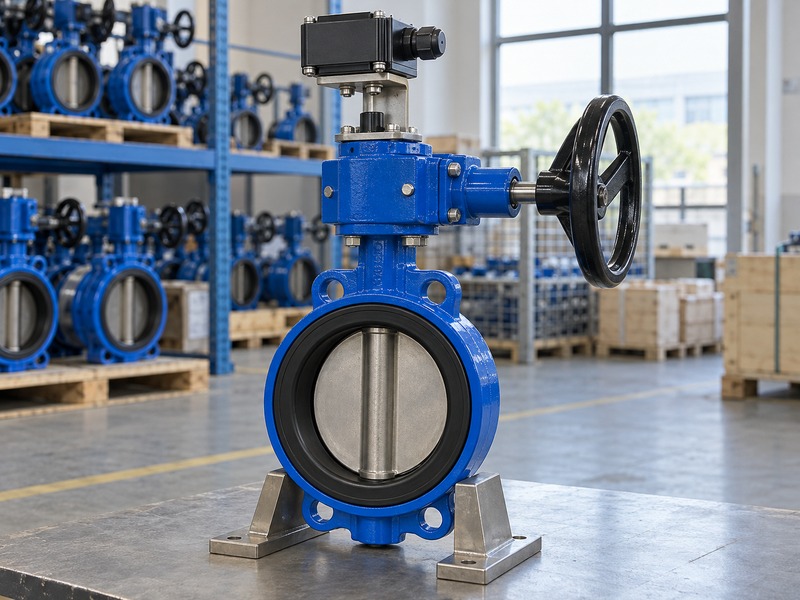
Which environmental assumptions cause trouble?
A box suitable for a dry indoor location may need a different arrangement for outdoor weather, washdown or a wet pit. The fitted cable entry must maintain the protection required by the selected device and installation. Check the actual accessory temperature at the valve location, including heat transfer from the process and surrounding insulation. Hazardous-location requirements apply to the exact equipment and installation, not to a generic label used in a quotation.
A manual butterfly valve with limit switch on building services still needs moisture, access and cable-routing review. Keep the enclosure and cable arrangement clear of moving operator parts. If the project changes the mounting position, repeat the clearance and environmental checks before approving the revised assembly.
- State the actual external environment.
- Check glands and mounting as part of the assembly.
- Review location-specific requirements separately.
| Exposure | Review |
|---|---|
| Moisture or washdown | Enclosure and cable-entry protection |
| Heat or cold | Accessory operating conditions |
| Restricted location | Exact equipment and installation suitability |
7. What should commissioning prove?
Commission a manual butterfly valve with limit switch by comparing actual valve travel, mechanical indication and each defined electrical input. Check the approved endpoint settings under controlled conditions. Position feedback and seat leakage remain separate acceptance tasks, so a closed input must not be used as the sole proof of tight isolation.
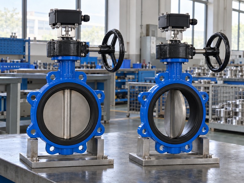
How should you record the functional check?
Identify the valve, operator, accessory and wiring revision before the check. Move the assembly through its approved procedure and record each input at the required mechanical positions. Verify intermediate and unavailable-signal behavior as defined by the controls design. Where the contract selects ISO 5208, keep metallic-valve pressure-test records separate from switch-function results.
The standard's valve-test scope does not replace the site's test-safety procedure or the electrical commissioning plan. Check that the mounting remains secure and the cable stays clear through the full stroke. If the switch changes too early, too late or inconsistently, investigate its approved adjustment and mechanical correspondence before returning the input to service.
- Compare physical movement with each input.
- Record endpoints and defined abnormal states.
- Keep sealing and electrical tests separate.
| Acceptance check | Evidence |
|---|---|
| Mechanical travel | Approved disc and operator positions |
| Signal function | Recorded input states |
| Sealing | Separate specified leakage test |
8. How do you investigate a false position indication?
For a manual butterfly valve with limit switch, compare the physical assembly and electrical signal path before adjusting the reported position. Loose couplings, moved cams, damaged wiring and incorrect system logic can produce similar symptoms. Follow the site's isolation and control-authority procedures before disturbing the valve, switch or interlock input.
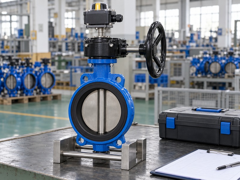
Which observations help locate the fault?
Record the actual valve position, local indicator and controller input at the same time where the approved procedure allows. Note whether the problem occurs at one endpoint, in both directions or after a mounting change. Check the accessory identification and final wiring diagram against the installed hardware. A manual butterfly valve with limit switch service enquiry should include clear photographs and the observed states rather than only reporting that the light is wrong.
Do not move a cam to hide coupling slip or change logic to bypass an unresolved mechanical fault. Restore the approved relationship between the disc, feedback mechanism and system interpretation. After corrective work, repeat the relevant functional checks and retain the revised record with the assembly.
- Record physical and electrical states together.
- Check recent mounting or wiring changes.
- Revalidate after corrective work.
| Mismatch | Investigation area |
|---|---|
| Local and disc positions differ | Coupling and mechanical connection |
| Device and controller states differ | Wiring and input interpretation |
| Switching point changed | Mounting, cams and adjustment |
9. What should the purchase specification include?
A manual butterfly valve with limit switch specification should define the valve duty, manual operator, monitoring interface, electrical outputs, environment and acceptance plan. Include the required drawings and input-output schedule. These details prevent an accessory that fits mechanically from arriving with incompatible signals or incomplete installation information.
How do you control the supplied configuration?
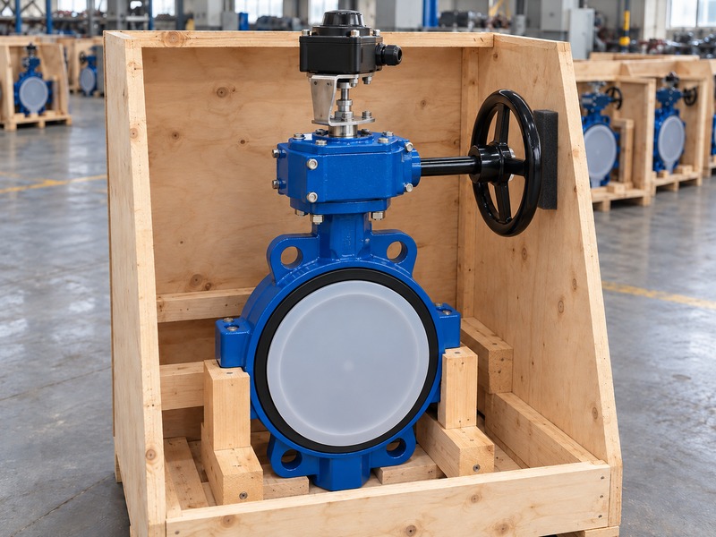
List the valve, gearbox or lever, bracket, coupling and switch assembly as one reviewed package. Require the exact accessory data sheet and wiring diagram before final approval. Agree who supplies the cable glands, field cable, controller configuration and site functional checks. Keep any special location or protective-function requirement explicit rather than inferring it from the existence of a limit switch.
If a supplier proposes a different accessory, compare the signal, mounting and environmental details before accepting it. RUITO can review the valve and operator arrangement together with the requested accessory scope, subject to the actual project configuration. Retain the accepted drawings, terminal schedule and commissioning results so future maintenance does not depend on a generic product photograph.
- Approve the complete mechanical and signal package.
- Define factory and site scope.
- Control accessory substitutions.
| Specification area | Required information |
|---|---|
| Valve and operator | Duty, torque and mounting |
| Feedback | Positions, outputs and logic |
| Delivery | Data sheets, diagrams and acceptance records |
10. What do buyers ask about manual valve limit switches?
Q1. Can a limit switch open the valve remotely?
No. It reports position. Remote movement requires a suitable actuator and control arrangement.
Q2. Does a closed signal prove that the seat is tight?
No. It represents the monitored mechanical position. Sealing needs the specified independent leakage acceptance check.
Q3. Can I wire every limit-switch box the same way?
No. Use the exact device diagram, output type and control-system input design. Similar housings can contain different switches or sensors.
Q4. Does loss of feedback mean the valve closed?
Not necessarily. The cause can include intermediate travel, wiring failure or lost sensor supply. The approved logic must define the required response.
Q5. Can I treat the assembly as a certified safety function?
Only when the exact equipment and complete function satisfy the project's required design and validation. A position switch alone does not establish that status.
Send the valve duty, required position signals and input specification when you contact us. RUITO can review the manual assembly and the mounting, accessory and documentation scope needed for the project.