
Avoid manual lever butterfly valve mistakes by checking the duty, locking mechanism and permitted operating movement before applying force. The lever turns the disc directly through its approved quarter-turn travel. If the handle jams or the process changes unexpectedly, stop and investigate the valve and system conditions rather than fitting a longer handle.
1. How does a manual lever butterfly valve work?
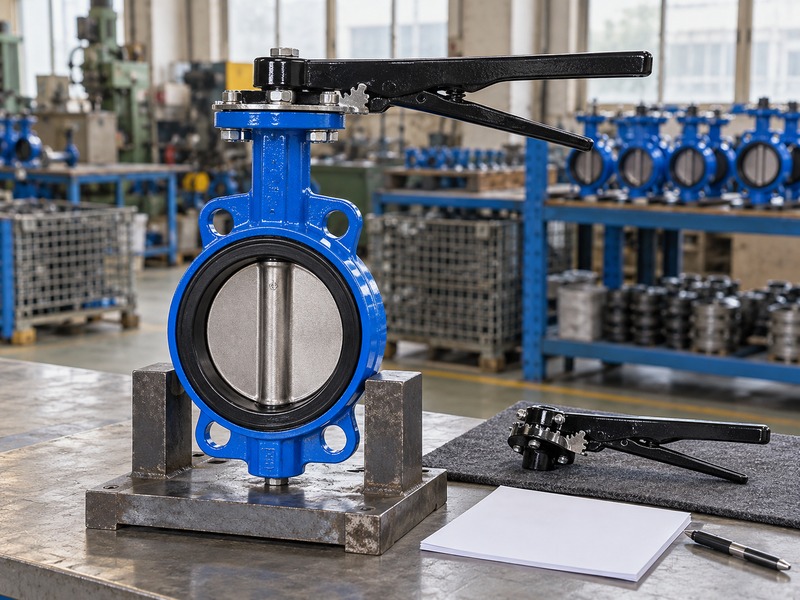
A manual lever butterfly valve connects a hand-operated lever to the valve stem so the user's movement rotates the disc. The selected handle may include a trigger, toothed quadrant or another approved holding mechanism. The exact operator design determines how you release, move and secure the handle.
Which parts should you identify before operation?
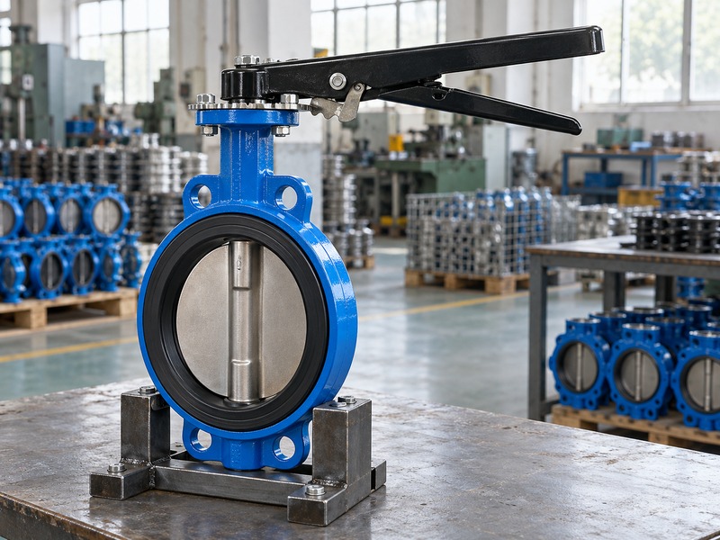
Identify the lever, its stem connection, the position-holding parts and any stop features shown in the operating instructions. The disc rotates inside the valve body rather than moving along the pipe like a gate. A direct lever normally follows the stem's quarter-turn movement, while a geared wheel has a different input motion. Do not infer the operating direction or end position from the handle appearance alone.
A replaced or incorrectly fitted handle can show a misleading position. Use the approved assembly and indication method for the selected valve. If identification is missing or the handle differs from the drawing, resolve that discrepancy before treating it as a familiar manual operator.
- Identify the handle and holding mechanism.
- Confirm the approved direction and travel.
- Resolve missing or inconsistent identification.
| Part | Check |
|---|---|
| Lever connection | Correct stem fit and retention |
| Holding mechanism | Approved release and engagement |
| Stops or indication | Correspondence with disc travel |
2. How should you release the position lock?
Release a manual lever butterfly valve using the selected operator's instructions, without forcing a latch or dragging it across the holding features. A trigger handle and a separate locking device may work differently. Confirm that the handle can move through the required path before releasing a position restraint under service load.
What should an operator inspect around the latch?
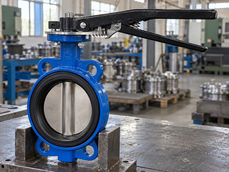
Look for bent parts, loose fasteners, deposits or damage that prevents the locking components from engaging as intended. Keep fingers away from pinch points and maintain a stable grip appropriate to the operating procedure. A handle under hydraulic load may move differently from an unloaded sample on a bench. Do not remove the latch or holding plate merely to make an uncomfortable movement easier.
The operator may rely on that assembly to retain its selected position. If the mechanism sticks, use the site's safe inspection process and the manufacturer's approved maintenance method. After a repair or replacement, verify release and re-engagement through the relevant operating positions before accepting the handle for service.
- Use the model-specific release method.
- Inspect damaged or obstructed locking parts.
- Verify re-engagement after corrective work.
| Finding | Action |
|---|---|
| Latch will not release | Investigate under the approved procedure |
| Worn holding feature | Review approved replacement parts |
| Incomplete engagement | Do not assume the position is secured |
3. What should you check before moving the valve?
Before moving a manual lever butterfly valve, confirm the permitted process action, pressure conditions and available operating space. The valve may control an active branch, pump circuit or equipment isolation boundary. Local handle movement can change flow quickly, so follow the system's operating procedure rather than treating every valve as an unloaded test sample.
Which process inputs affect manual operation?
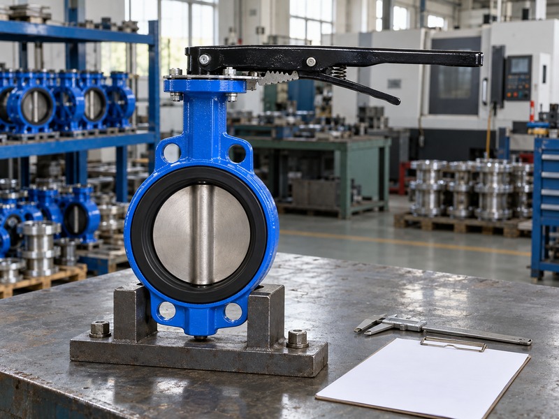
Check the fluid, temperature and maximum differential pressure against the approved duty. Include any recent changes in pump operation, connected equipment or trapped pressure. A manual lever butterfly valve on a water circuit still requires a system-level operating sequence when filling, draining or isolating equipment. The lever's convenient quarter-turn movement does not establish a safe closing time for every pipeline.
Confirm that no maintenance isolation, lock or permit prohibits movement. Check the full lever sweep for contact with nearby pipes, supports or personnel access routes. If operation would require an unstable stance or excessive reach, resolve the access problem before using force. Record abnormal conditions so the responsible team can review the task.
- Confirm the permitted process action.
- Check duty and any active isolation restrictions.
- Keep the full handle sweep clear.
| Pre-operation item | Purpose |
|---|---|
| Process sequence | Avoid an unintended flow change |
| Differential pressure | Check operating load |
| Access and sweep | Maintain controlled manual movement |
4. How does lever length affect hand force?
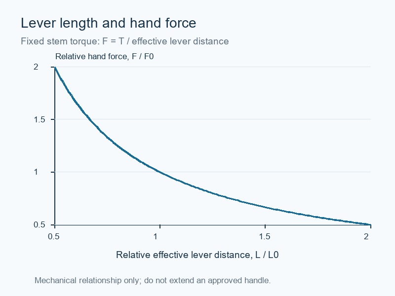
For a manual lever butterfly valve, a longer effective lever arm reduces the tangential force needed for the same stem torque, provided the force acts in the intended direction. That mechanical relationship does not authorize a longer replacement handle. The lever, stem and holding mechanism still have approved load limits.
Why should you avoid improvised extensions?
At the lever, torque equals applied tangential force multiplied by effective distance from the stem axis. A normalized chart can explain the relationship without claiming a product torque rating. Actual users may grip the handle closer to the stem or push at an angle, changing the effective input. A pipe slipped over the handle can greatly increase available torque and overload parts that appear undamaged from outside.
It can also defeat the intended access and locking arrangement. If the specified handle requires excessive effort, compare the actual differential pressure and mechanical condition with the original selection. An approved gearbox or different operator may be appropriate, but that decision requires a complete interface and torque review rather than a field-made extension.
- Use effective lever distance.
- Stay within the approved input load.
- Investigate effort before changing the operator.
| Variable | Review |
|---|---|
| Lever distance | Force needed for a given torque |
| Applied angle | Effective tangential force |
| Available input | Stem and operator load limits |
5. How should you move through the approved travel?
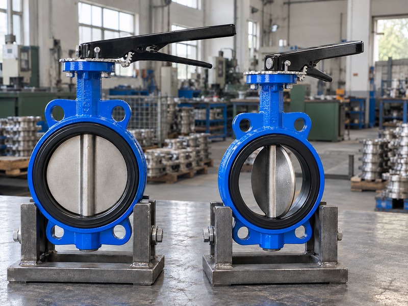
Move a manual lever butterfly valve through the direction and range specified for the selected assembly, keeping the operator under control. Release and re-engage its holding mechanism as instructed. Do not assume a universal clockwise direction, handle orientation or closing speed from another valve that looks similar.
What should happen if travel stops unexpectedly?
Stop at unexpected resistance and compare the observed position with the approved travel. A mechanical collision, a seat obstruction and an intended end stop require different responses. Do not push past a stop or remove a holding component to gain extra travel. A manual lever butterfly valve installed between pipe flanges also needs clearance for the disc in the actual adjoining bore.
If the movement becomes restricted after installation, check the interface under the approved isolated procedure. Successful operation on a workbench does not prove clearance in a lined pipe or next to a reducer. After an approved adjustment or repair, verify the relationship between the handle, stop and disc before returning the assembly to the operating procedure.
- Follow the selected direction and range.
- Stop at unexplained resistance.
- Recheck actual disc clearance after installation.
| Travel condition | Response |
|---|---|
| Approved endpoint | Use the specified stop and lock |
| Unexpected resistance | Investigate before applying more force |
| Changed installation | Review clearance and alignment |
6. Can the lever hold a partial opening?
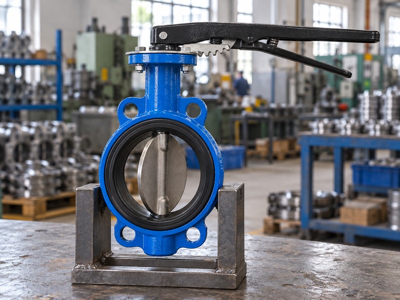
A manual lever butterfly valve can hold a partial opening only within the selected operator's approved positions and the valve's permitted throttling duty. A toothed plate may provide discrete positions rather than continuous adjustment. A secured handle does not establish a fixed flow rate or prove safe maintenance isolation.
What should you confirm for an intermediate position?
Ask for the permitted operating range, pressure difference and hydraulic loading for the selected valve. The disc's flow characteristic is nonlinear, so an intermediate angle does not correspond directly to the same percentage of maximum flow. Changes in system pressure also change the resulting flow. Check that the holding mechanism can retain the intended position under the stated service conditions.
A worn latch or incompletely engaged tooth should not be accepted as normal positioning. If the process requires accurate balancing or automatic regulation, review a product and control arrangement designed for that task. Keep position restraint, leakage performance and the site's isolation procedure as separate requirements in the operating instructions and purchase specification.
- Use approved holding positions.
- Check actual throttling limits.
- Separate position restraint from flow measurement.
| Feature | Limit to recognize |
|---|---|
| Discrete quadrant | Only specified holding positions |
| Intermediate disc angle | Nonlinear flow relationship |
| Locked handle | No independent proof of sealing |
7. How do you investigate a stuck handle?
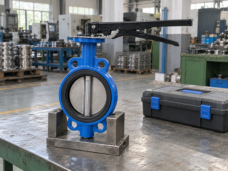
Investigate a stuck manual lever butterfly valve by checking the process load, holding mechanism and mechanical assembly under the approved safe procedure. Do not assume corrosion is the only cause. A changed differential pressure, trapped debris, misalignment or internal damage can create resistance at different points in the stroke.
Which details help identify the cause?
Record whether the handle fails to release, stops near one endpoint or resists movement throughout the stroke. Note when the problem began and any recent service or pipework change. Check external parts for obvious damage without disturbing a pressurized boundary. If inspection requires operator removal or valve disassembly, isolate and depressurize according to the model and site procedures first.
Do not strike the lever or use a bar to overcome the fault. Extra force can damage the stem connection or seat without removing the obstruction. Provide the supplier with identification, fluid conditions and clear photographs, then use approved replacement parts and repeat the relevant travel and leakage checks after corrective work.
- Describe the point and pattern of resistance.
- Record recent service or pipework changes.
- Use approved inspection and repair procedures.
| Observation | Check direction |
|---|---|
| Cannot release latch | Holding mechanism condition |
| Stops at one position | Interference, obstruction or stop setting |
| High effort throughout | Duty, alignment and assembly condition |
8. What maintenance records should you keep?
Keep the manual lever butterfly valve identification, approved operator details and service observations in the maintenance record. Record changes in effort, locking or leakage. The maintenance interval and lubrication instructions depend on the selected model and duty, so a generic schedule should not replace its operating manual.
How should you handle replacement parts?
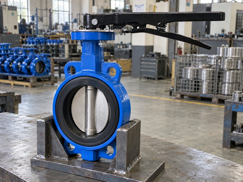
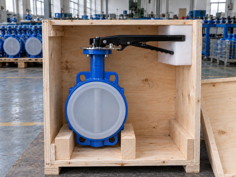
Order the lever, latch, holding plate, stem connection and other parts from the approved specification. A similar-looking handle can have a different drive geometry, length or retention method. Review any substitution before fitting it to a valve that remains part of an approved equipment package. A manual lever butterfly valve support enquiry should include the actual assembly identification and inspection findings so the engineering team can identify the correct configuration.
Protect the disc edge and seat during handling, and keep unsuitable cleaning or lubricating materials away from wetted parts. After maintenance, verify movement and position holding using the approved procedure. Keep the resulting record with the installed valve for future operators and spare-part orders.
- Retain approved operator identification.
- Record changes in effort and holding.
- Review substitutes before fitting.
| Record | Use |
|---|---|
| Operator parts | Compatible replacement selection |
| Service observations | Fault history and trend review |
| Post-maintenance check | Confirmed travel and holding |
9. When should you consider a gearbox instead?
Consider replacing a manual lever butterfly valve operator with a gearbox when the approved lever effort, sweep or positioning arrangement does not meet the operating task. The conversion must match the valve's torque, stem and mounting limits. A gearbox is an engineering change rather than a universal accessory for any quarter-turn valve.
What should a conversion package contain?
Provide the valve identification, duty and reason for the change to the supplier. Request the selected gearbox, coupling, bracket if needed and complete installation envelope. Compare the resulting wheel effort and number of turns with the actual operating frequency and access. Confirm that the conversion preserves the required travel and indication without overloading the valve stem.
Any lock or feedback accessory must also suit the new arrangement. Do not remove the existing operator from a pressurized valve unless an approved model-specific procedure explicitly permits the task. After the authorized conversion, record the new assembly details and complete the required functional checks. Retain the changed drawing and spare-parts information so future maintenance follows the installed configuration.
- Define the operating problem to solve.
- Approve torque and mechanical interfaces.
- Update drawings and maintenance information.
| Conversion input | Approval check |
|---|---|
| Service torque | Gearbox and stem compatibility |
| Operating task | Effort, turns and access |
| New assembly | Travel, locking and records |
10. What do operators ask about lever butterfly valves?
Q1. Can I assume clockwise always closes the valve?
Use the selected assembly's direction and indication. A generic habit or handle photograph cannot replace its approved operating information.
Q2. Can I add a pipe to make the handle easier to turn?
Do not use an improvised extension. Investigate the load or fault and review an approved operator change if needed.
Q3. Does a locked handle prove the pipe is safely isolated?
No. It restrains the selected position within its design. Follow the site's isolation and verification procedure for maintenance.
Q4. Can I hold exactly any disc angle with a trigger handle?
Not necessarily. A quadrant may provide discrete holding positions. Use the operator's specified range and mechanism.
Q5. How do I know when to stop operating a stiff valve?
Stop at unexplained resistance or changed effort. Record the position and process conditions, then follow the approved investigation procedure.
Send the valve identification, service duty and handle problem when you contact us. RUITO can review the existing manual arrangement and identify suitable inspection, replacement or conversion information.