
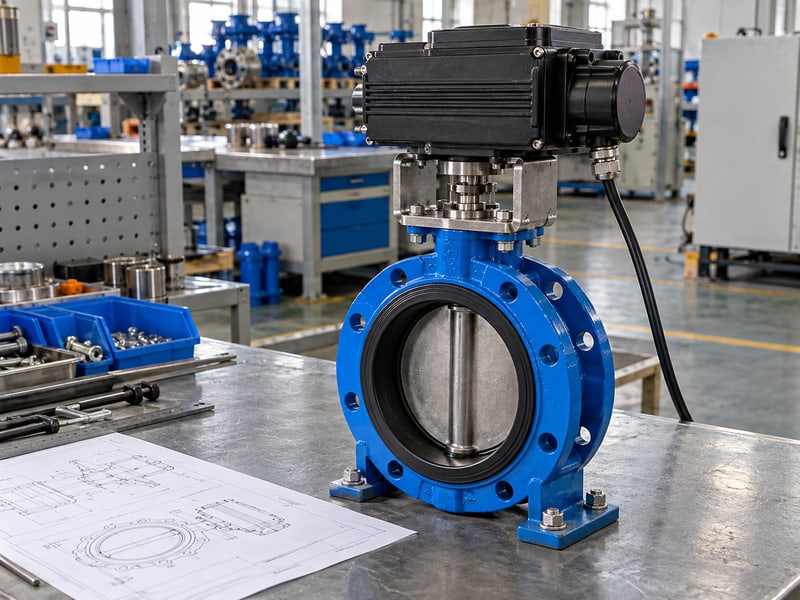
Fix motor operated butterfly valve mistakes by checking prestart readiness, following the approved operating sequence, and comparing movement with verified feedback. A valve that responds locally can still be unready for automatic service. Use the assembly instructions and project commissioning procedure to define acceptance, fault response, and handover records.
1. What prestart checks does a motor operated butterfly valve need?
Prestart checks establish whether the installed motor operated butterfly valve and surrounding process are ready for the planned operation. Confirm assembly identification, installation acceptance, available supply, control readiness, and the required process conditions before enabling movement.

What should the readiness review compare?
Match the installed unit to its accepted records. Check the valve and actuator identification against the approved drawings, instructions, and settings sheet. Include outstanding installation items, access restrictions, and any changes made after the supplier's assembly verification.
- Confirm installation and inspection acceptance.
- Check supply and control availability.
- Identify process permissions and open items.
For water and wastewater facilities, starting a valve movement may change which equipment receives flow. The operating team should confirm the intended plant sequence and nearby equipment status, rather than treating actuator power availability as permission to move the valve.
What permits the next commissioning stage?
Key takeaway: Readiness includes the process and the complete installed assembly. Keep unresolved items visible so the next stage begins under conditions the responsible teams have accepted.
| Readiness item | Evidence |
|---|---|
| Installation | Accepted inspection record |
| Controls | Approved settings and availability |
| Process | Permission for planned movement |
Complete the readiness sheet before the scheduled check. Hold affected stages until missing records or operating restrictions are resolved.
2. What service limits apply to a motor operated butterfly valve?
The selected valve and actuator limits govern a motor operated butterfly valve throughout commissioning and operation. Check fluid composition, temperature, pressure, closing differential, operating duty, and external conditions against the approved configuration and intended sequence.

Which operating conditions need review?
Check closing differential alongside line pressure. A body pressure rating does not describe every load the disc and drive encounter during closure. Directional closing limits, where specified, and the actuator's operating requirements must agree with the actual service conditions.
- Confirm the selected fluid and temperature envelope.
- Review closing differential and flow conditions.
- Check operating frequency and supply constraints.
For flanged butterfly valves, use the approved model documents to confirm the accepted duty and operating arrangement. Do not infer bidirectional shutoff capability or permitted throttling from the connection style; the selected construction and stated application define those limits.
How should limits remain available to operators?
Key takeaway: Keep service constraints beside the operating procedure. A commissioning check under one condition does not establish approval for every later pressure, fluid, or duty change.
| Condition | Acceptance reference |
|---|---|
| Process service | Selected valve data |
| Closing load | Approved differential limits |
| Drive duty | Actuator operating instructions |
Record the conditions used for the check. Review proposed service changes before repeating the operation under a different duty.
3. How is a motor operated butterfly valve run locally?
Operate a motor operated butterfly valve locally through its approved selector and command sequence once readiness and process permissions are accepted. The procedure should identify who controls movement and which local functions are available on the fitted actuator.
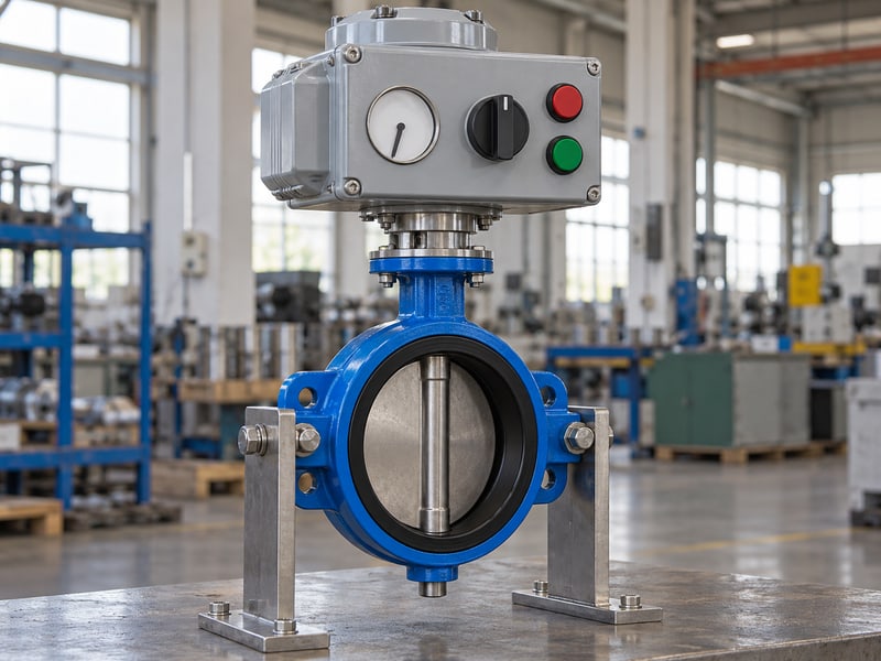
What should the local sequence define?
Confirm local control before issuing a movement command. Check the selected mode and any interlocks that remain active in that mode. Local selection may change remote-command availability, but its exact effect depends on the configured controller and project sequence.
- Identify the permitted local commands.
- Confirm movement area and process readiness.
- Observe the response and required indication.
Use the accepted open, close, or stop procedure for the fitted unit. If the response differs from the expected action, follow the fault procedure before issuing another command; changing selector positions repeatedly can make the original condition harder to reconstruct.
What should the local check record?
Key takeaway: Record the selected mode, issued command, and observed response together. This establishes what the local operating stage demonstrated before remote or automatic checks begin.
| Local check | Record |
|---|---|
| Selection | Accepted operating mode |
| Command | Intended action |
| Observation | Movement and indication |
Complete the local-stage record against the agreed acceptance criteria. Resolve a discrepancy before advancing to a sequence that depends on that function.
4. How is a motor operated butterfly valve run remotely?
Remote operation of a motor operated butterfly valve follows the approved controller sequence, command permissions, and feedback requirements. Confirm that the actuator is in the required mode and that the control system identifies the intended valve before enabling remote commands.
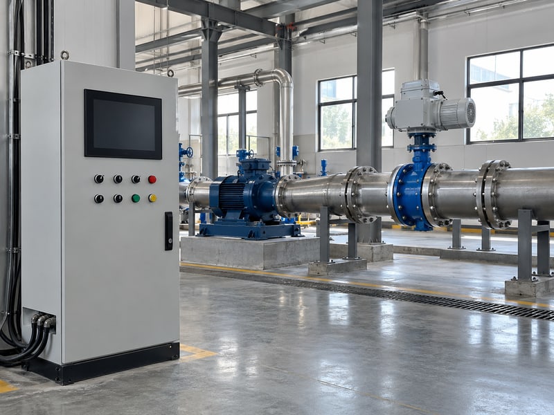
What should controls and operations agree?
Identify which system owns the command. A remote signal may come from a local panel, plant controller, or an automatic sequence, and their priorities need definition. Check permissives and interlocks against the accepted operating procedure rather than assuming remote selection enables every requested action.
- Verify the valve tag and selected mode.
- Confirm command priority and permissions.
- Agree the required response and feedback.
In HVAC and district energy systems, valve movement may be coordinated with pumps or other isolation points. The agreed sequence should describe that coordination and the response to unavailable feedback; a successful command to one actuator cannot establish the readiness of the whole circuit.
What supports acceptance of the remote stage?
Key takeaway: Remote checks must connect the correct command source with observed valve behaviour. Record control-system interpretation as well as the actuator's local indication.
| Remote check | Compare |
|---|---|
| Command source | Approved control priority |
| Permission | Accepted interlock conditions |
| Feedback | Verified local response |
Check individual functions before combining them into an automatic sequence. Retain the accepted conditions and results with the commissioning record.
5. How is a motor operated butterfly valve stroke verified?
Verify a motor operated butterfly valve stroke by observing the approved travel and comparing its endpoints and feedback with the accepted valve references. Use the prescribed process conditions and test method for the assembled drive and valve.
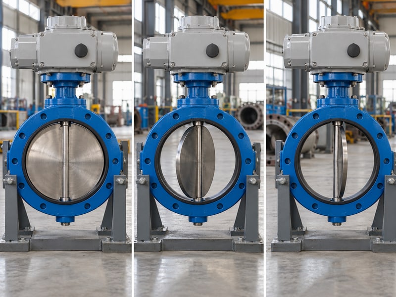
Which observations should you collect?
Record movement across the planned stroke. Note the command, operating mode, relevant supply and process conditions, endpoint indication, and any unexpected interruption. Where stroke duration is part of acceptance, compare it with the approved requirement for that assembly and condition.
- Check the intended direction of movement.
- Compare endpoints with approved references.
- Record feedback agreement and interruptions.
A motor that stops does not independently prove the disc reached its accepted seating position. An actuator position value cannot establish leakage performance; functional travel and any required valve sealing verification need their own agreed acceptance methods.
How should a stroke result be interpreted?
Key takeaway: Compare the observed stroke with defined criteria under recorded conditions. Avoid assigning a universal duration or percentage band to every electric butterfly-valve assembly.
| Observation | Acceptance basis |
|---|---|
| Travel | Approved valve references |
| Duration, if specified | Assembly requirement |
| Feedback | Accepted signal mapping |
Investigate an unexplained change from the accepted behaviour. Repeat affected checks after a reviewed correction and preserve the final record.
6. What stops protect a motor operated butterfly valve?
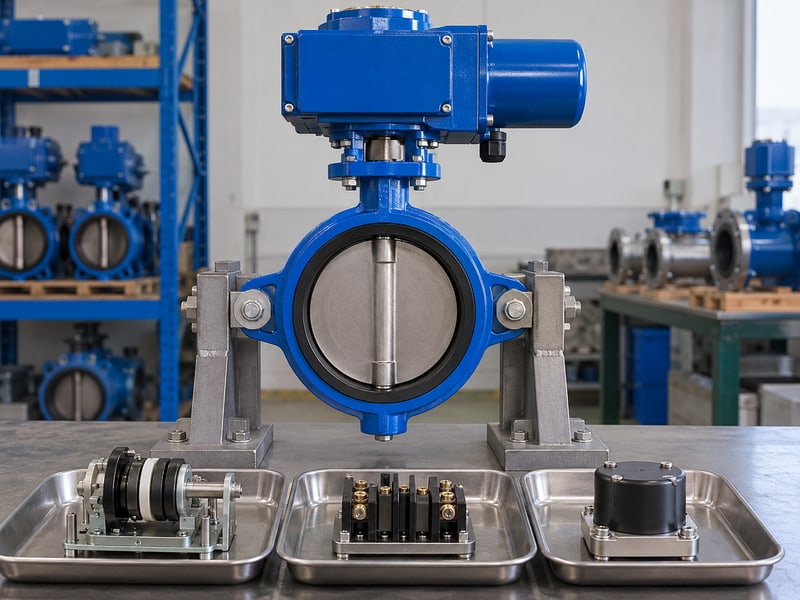
The approved travel limits, stopping functions, and protective settings protect a motor operated butterfly valve from movement beyond its intended operating conditions. Their functions and accepted values depend on the selected valve, drive train, and actuator controller.
What should an unexpected stop trigger?
Investigate the stop before resetting protection. Identify whether the event came from a command, travel limit, protective trip, interlock, or another documented function. Preserve the indication and operating conditions so the team can distinguish a normal endpoint from an unresolved fault.
- Identify the stopping function that acted.
- Compare its indication with the accepted procedure.
- Record the conditions before further operation.
Do not raise torque settings or move a travel stop to force an unexplained closure. Incorrect endpoint settings, installation interference, or a changed process load can require different corrective action, and additional drive force can damage the assembly while leaving the cause unresolved.
What should protection records show?
Key takeaway: Keep protective settings tied to the approved assembly requirements. A successful reset does not establish that the original cause has been corrected.
| Stop event | Check |
|---|---|
| Commanded stop | Agreed operating response |
| Endpoint stop | Verified travel reference |
| Protective trip | Cause and authorised correction |
Follow the accepted fault and reset procedure. Recheck the affected functions before returning the valve to its intended operating mode.
7. What loss responses must a motor operated butterfly valve meet?
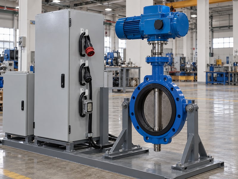
A motor operated butterfly valve must meet the separately specified responses to loss of operating supply, control supply, and command signal where applicable. The approved sequence should also define what happens to indication and movement when each source returns.
Which conditions need separate acceptance?
Define the loss event before testing the response. A powered controller receiving no valid command can behave differently from an actuator with no operating energy. Any required final position or retained state needs confirmation against the fitted mechanism, reserve-energy arrangement, and configured settings.
- State the source or signal being lost.
- Define the required movement and indication.
- Confirm recovery and restart behaviour.
Use the approved controlled procedure to verify loss responses without creating an unreviewed process change. An electric drive does not universally close on power loss, and a manual override does not independently satisfy an automatic final-position requirement.
What belongs in the failure-response record?
Key takeaway: Record each loss and recovery condition separately. The operating team needs to know which indications remain valid and whether restoration can initiate movement.
| Condition | Defined response |
|---|---|
| Supply loss | Movement or retained state |
| Signal loss | Configured controller action |
| Restoration | Restart and indication sequence |
Agree the expected responses before conducting the checks. Resolve an unmet requirement through an approved configuration or design review before handover.
8. How is a motor operated butterfly valve operated manually?
Manual operation of a motor operated butterfly valve uses the fitted override only through the actuator instructions and approved site procedure. Confirm the required power state, control isolation, process permission, and engagement method before using a handwheel or other manual input.

What should the override procedure specify?
Prevent unexpected powered movement before engaging the override. Follow the approved method for controlling remote commands and any stored energy, including reserve supplies where fitted. The procedure must identify the permissible process conditions and who authorises manual movement.
- Confirm override engagement and disengagement steps.
- Check the marked operating direction and indication.
- Define the return to powered operation.
An override arrangement can differ between actuator models, so avoid copying an engagement sequence from a visually similar unit. Do not use an extension bar to overcome unexplained resistance or disconnect a loaded mounting arrangement to make manual movement easier.
What should be checked after manual operation?
Key takeaway: Manual operation includes a controlled return to the required operating mode. Confirm disengagement, position indication, and command readiness through the specific instructions before enabling power-driven movement.
| Override stage | Required check |
|---|---|
| Preparation | Control, energy, and process conditions |
| Manual movement | Approved method and indication |
| Return | Disengagement and mode readiness |
Record the manual intervention and final valve state. Carry out the required recovery checks before returning control to the automatic sequence.
9. How are motor operated butterfly valve faults handled?
Handle motor operated butterfly valve faults through the approved operating and diagnostic procedure, preserving the evidence before further movement. Control the process consequences, identify the reported condition, and obtain the required authority for investigation or corrective work.

Which observations help diagnosis?
Keep the command and conditions with the fault indication. Record the operating mode, requested action, observed travel, feedback, and relevant supply and process conditions. Those details can distinguish a missing permission from an interrupted stroke or a mismatch between local and remote indication.
- Capture the fault or status message accurately.
- Record when and during which action it appeared.
- Identify recent approved changes or maintenance.
Operating records should also retain accepted behaviour and later changes in movement or indication. Avoid repeated resets as a substitute for diagnosis, and keep electrical inspection, process checks, and mechanical intervention within their authorised isolation procedures.
What should corrective-action records contain?
Key takeaway: Link the fault, identified cause, approved correction, and recheck results. A record of restored movement alone can leave the original operating discrepancy unexplained.
| Record | Purpose |
|---|---|
| Fault observations | Reconstruct the event |
| Approved correction | Trace the action taken |
| Recheck results | Confirm affected functions |
Send the supplier equipment identification and the recorded conditions when support is needed. Retain the final findings before releasing the valve back to service.
10. What motor operated butterfly valve records support handover?
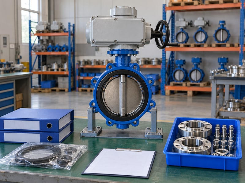
Handover of a motor operated butterfly valve needs accepted operating instructions, configured settings, commissioning results, and replacement information matched to the installed assembly. Operations and maintenance should receive the same final configuration and unresolved-item status used for release.
What should operations and maintenance receive?
Specify spares against the accepted configuration. Keep the valve, actuator, drive connection, controller options, and relevant material details identifiable in the replacement records. Nominal valve size alone cannot establish whether a spare operator or internal component matches the installed unit.
- Retain final drawings and equipment identification.
- Provide operating and fault-response procedures.
- Identify approved spares and replacement requirements.
Include the local, remote, loss-response, and manual-override records accepted during commissioning. Where replacement requires resetting endpoints or confirming control mapping, the maintenance instructions should identify those checks so changing a part does not leave the operating sequence unverified.
What should the release document confirm?
Key takeaway: Handover combines configuration records with accepted operating evidence. Close missing instructions and unresolved discrepancies before releasing the valve for the intended automatic duty.
| Handover item | Use |
|---|---|
| Operating instructions | Accepted sequence and limits |
| Commissioning record | Verified functions and conditions |
| Spares information | Reviewed replacement selection |
Send RUITO the service data, installed assembly identification, and required operating sequence; contact us today to review the supporting documents. Request the applicable instructions, spares details, and agreed verification scope with the selected valve assembly.
Frequently asked questions
Q1: Can I approve remote operation after a successful local check?
Approve it only after the required remote checks also pass. Confirm command ownership, permissions, feedback interpretation, and the agreed automatic sequence for the installed configuration.
Q2: What's the best way to judge a slow valve stroke?
Compare it with the accepted assembly requirement under recorded conditions. Supply, process load, operating mode, and an interruption can affect the observation.
Q3: Can I reset a protective trip and continue operating?
Follow the approved diagnostic and reset procedure. Identify the cause and complete the required rechecks before returning the valve to its operating duty.
Q4: How do I know whether manual override is safe to use?
Check the specific instructions and site procedure. Confirm power and control isolation, stored energy, process permission, engagement, and recovery requirements before manual movement.
Q5: Can I order spare actuator parts using only valve size?
No. Identify the accepted actuator configuration and replacement requirements, including the drive connection, controller options, applicable settings, and required verification after fitting.