
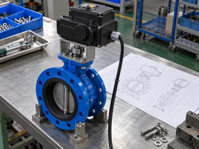
Fix motorized butterfly valve specification errors by separating buyer requirements, the supplier's offer, and the accepted configuration in one controlled datasheet. A quotation can look complete while leaving closing differential or failure behavior unresolved. Record missing inputs, assign their owners, and review the supporting drawings before releasing the order.
1. What belongs in a motorized butterfly valve specification?
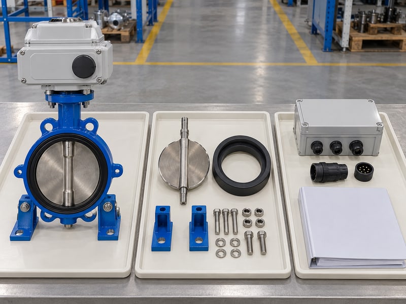
A motorized butterfly valve specification should define the required service, valve construction, actuator functions, interfaces, documents, and acceptance conditions for one identified assembly. Keep required values separate from offered values and accepted values. That separation lets your reviewers identify unresolved differences without searching through scattered quotation notes.
How should the datasheet be organized?
Give each assembly a clear identity. Use the project valve tag, duty description, quantity, and relevant drawing references before listing technical fields. State who supplies service data, who confirms the offered configuration, and who accepts deviations so an empty field cannot quietly become an assumed requirement.
- Identify the valve tag, project, duty, and datasheet revision.
- Separate buyer inputs from supplier confirmations and exceptions.
- Mark unresolved fields with an owner and review status.
What makes the sheet ready for review?
Key takeaway: Treat the datasheet as an agreed assembly definition. Its accepted revision should connect with the offered equipment and governing documents so purchasing can order the same configuration that engineering reviewed.
| Identity field | Blank input |
|---|---|
| Project and valve tag | [enter project and tag] |
| Duty and quantity | [enter intended duty and quantity] |
| Revision and review status | [enter revision, owner, and status] |
Create separate sheets where service or configuration differs. Keep unresolved entries visible until they are closed.
2. How does motorized butterfly valve specification define duty?
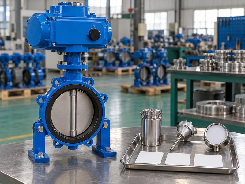
A motorized butterfly valve specification defines duty through the actual medium, operating pressures, temperatures, maximum closing differential, and required operating function. State these conditions together for the relevant cases rather than combining unrelated maxima. Design conditions, normal operation, and transient conditions should remain identifiable for the selection review.
Which service inputs need their own fields?
Write the fluid and pressure basis explicitly. Include composition, phase, concentration where relevant, additives, and solids that could affect sealing or movement. Closing differential means the pressure difference across the disc under the specified closing condition, so one upstream pressure value cannot always describe the required duty.
- State minimum, normal, maximum, and applicable transient conditions.
- Identify pressure units and whether values are gauge or absolute.
- Define isolation or regulating duty and the required service cases.
How do you avoid an incomplete medium description?
Key takeaway: Specify the actual fluid and its conditions before accepting materials or ratings. Hypothetical example: A cooling-water inquiry lists water and its inhibitor package, while the responsible engineer supplies the corresponding pressure and temperature cases.
| Service field | Blank input |
|---|---|
| Medium and composition | [enter fluid, additives, and phase] |
| Pressure and temperature cases | [enter concurrent values and units] |
| Maximum closing differential | [enter value, units, and condition] |
Request missing service data from its owner. Keep supplier assumptions separately identified for review.
3. What connections go in motorized butterfly valve specification?
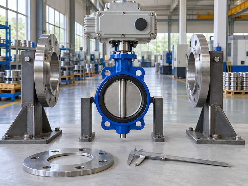
A motorized butterfly valve specification should identify size, connection style, flange or joint requirements, face-to-face dimensions, and the installation interfaces that affect the offered assembly. Nominal size alone does not define the pipe connection. Reference the accepted interface drawing where dimensions require more detail than the datasheet can show.
What should the interface fields describe?
Use the actual piping requirement. For a wafer butterfly valve, identify the companion flange arrangement and the pipe or flange bore information needed for disc clearance review. Include actuator envelope, access, mounting arrangement, and drive-interface references without assuming a mounting-standard designation proves complete interchangeability.
- Record connection standard, dimensional basis, and required face-to-face.
- Reference the pipe bore and installed disc-clearance review.
- Identify mounting, drive, access, and supporting drawing requirements.
How should special connection duties be recorded?
Key takeaway: State special installation conditions as separate requirements. If the project needs end-of-line isolation or a particular mounting arrangement, request confirmation for the exact offered configuration and the applicable conditions rather than accepting a general connection-style claim.
| Interface field | Blank input |
|---|---|
| Size and connection | [enter size, style, and standard] |
| Face-to-face and pipe interface | [enter requirement or drawing reference] |
| Actuator envelope and mounting | [enter constraints and accepted references] |
Send the relevant piping drawing with the inquiry. Resolve dimensional assumptions before accepting the assembly.
4. What materials belong in motorized butterfly valve specification?
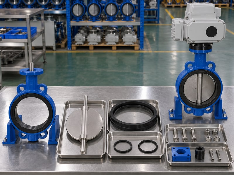
A motorized butterfly valve specification should describe the whole wetted material and seal configuration, together with pressure-retaining materials and relevant external protection. A body alloy or seat name alone cannot establish compatibility. Include the disc, exposed shaft parts, auxiliary seals, and any lining or backing involved in the selected construction.
How do you make the material schedule usable?
Identify each relevant component and condition. For a PTFE-lined butterfly valve, distinguish the fluid-contact lining, disc covering, backing, and shaft-seal arrangement. Ask the supplier to confirm the proposed materials against the stated medium and conditions, including cleaning fluids where they form part of the service.
- List specified materials separately from proposed alternatives.
- Identify lining construction and its required verification where applicable.
- Define traceability and material-document requirements for the order.
What should a material exception show?
Key takeaway: Review substitutions as changes to the complete configuration. The offered schedule should identify every exception and its service implications so an apparently similar material description cannot hide a different seal or wetted arrangement.
| Material field | Blank input |
|---|---|
| Body, disc, and shaft | [enter specified and offered materials] |
| Seat, backing, and auxiliary seals | [enter full seal configuration] |
| Lining and external protection | [enter construction and verification requirements] |
Compare the schedule with the assembly drawing. Carry accepted substitutions into the governing revision.
5. What supply goes in motorized butterfly valve specification?
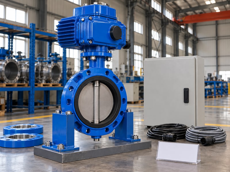
A motorized butterfly valve specification should state the available electrical supply, required operating duty, travel requirements, and environment for the actuator. Identify voltage, AC or DC, phases and frequency where applicable. Keep those inputs separate from output torque and the conditions used to confirm actuator selection.
Which operating demands should the buyer provide?
Describe the intended activity and surroundings. State whether the service needs occasional isolation, repeated operation, or approved modulation, then provide the expected movement and operating periods. Record ambient conditions, exposure, access, and project enclosure or hazardous-location requirements so the supplier can identify the relevant offered configuration and evidence.
- Enter supply details and any documented supply variation.
- Define operation frequency, travel time, and intended duty.
- Request service-specific torque selection and allowable-load confirmation.
How should the supplier respond?
Key takeaway: Require a confirmed actuator configuration and its limits. An available supply voltage or analog option cannot establish that the actuator meets the required duty, environmental conditions, or mechanical load.
| Actuator field | Blank input |
|---|---|
| Electrical supply | [enter voltage, AC/DC, phase, and frequency] |
| Duty and travel requirement | [enter frequency, activity, and travel time] |
| Environment and load evidence | [enter conditions and required confirmation] |
Flag incomplete supply or duty information. Accept the selection only after its supporting basis is reviewed.
6. What signals go in motorized butterfly valve specification?

A motorized butterfly valve specification should identify command signals, position or status feedback, operating-mode selection, and the applicable control interface. Define the required function and scaling for each signal. A generic description such as automatic valve cannot show how the supplied actuator must respond or what the control system will receive.
How do you separate signal requirements?
Record each signal's direction and meaning. Identify whether a command requests opening, closing, or an approved position and distinguish actuator feedback from a separate process measurement. Use analog, network, sourcing, or sinking arrangements only where the accepted input-output and wiring documents support the chosen interface.
- Specify command type, scaling, and direction of action.
- Define position, endpoint, availability, and fault feedback as required.
- Identify local-remote priority, interlocks, and document references.
What does a clear signal example look like?
Key takeaway: Specify the information exchanged rather than naming a control option alone. Hypothetical example: A position-control inquiry lists a desired-position command and actual-position feedback separately from the flow measurement used by the system controller.
| Signal field | Blank input |
|---|---|
| Command and scaling | [enter approved type, range, and action] |
| Required feedback | [enter each signal and its meaning] |
| Mode priority and interface | [enter logic and wiring reference] |
Review the signal schedule with the control-system owner. Resolve differences before approving the terminal documents.
7. What failures belong in motorized butterfly valve specification?

A motorized butterfly valve specification should define the required response to each relevant failure event, including loss of command signal and loss of electrical power separately. A general fail-safe label leaves the triggering event and expected behavior unclear. The responsible process review must establish the requested action before equipment capability is accepted.
What should the failure-event matrix state?
Pair each event with a required response. Identify the resulting position or action, its priority, and the conditions under which it must occur. If the offered arrangement uses stored energy, request its configuration and verification basis rather than assuming an electric drive can complete the requested movement without mains power.
- State command loss, power loss, and other required events separately.
- Identify requested action, priority, timing, and reset behavior where relevant.
- Request capability confirmation and an agreed verification method.
How do you describe an illustrative failure requirement?
Key takeaway: Accept failure behavior by event and confirmed capability. Hypothetical example: A project requests holding position after command loss but movement to a designated position after power loss; those requests still need process approval and equipment confirmation.
| Failure-event field | Blank input |
|---|---|
| Triggering event | [enter event and detection condition] |
| Required action and priority | [enter approved response and reset logic] |
| Capability and verification | [enter offered arrangement and test basis] |
Keep unresolved actions marked for process review. Avoid treating the failure matrix as approved until its decisions are recorded.
8. What files govern motorized butterfly valve specification?

A motorized butterfly valve specification should identify the governing datasheet, accepted drawings, operating instructions, electrical documents, and inspection requirements by revision. Establish the agreed order of precedence where project documents could conflict. A drawing reference without a revision can leave production and installation teams working from different assembly definitions.
Which documents should the register include?
Connect each file with the accepted assembly. Include the general arrangement, pipe interface, mounting arrangement, material schedule, torque basis, wiring or terminal documents, and applicable installation, operation and maintenance instructions. Define when each file is required and who reviews it so document approval follows the procurement and production sequence.
- Record identifiers, revisions, status, and responsible reviewers.
- Match valve and actuator identification across the package.
- Require controlled updates when an accepted configuration changes.
How do you handle a document disagreement?
Key takeaway: Resolve conflicting requirements through a recorded decision. Correct the affected datasheet and files together, then identify which units or order releases use the resulting revision instead of leaving installation staff to choose between competing documents.
| Governing-file field | Blank input |
|---|---|
| Datasheet and drawings | [enter identifiers, revisions, and status] |
| Operating and electrical files | [enter required files and submission stage] |
| Precedence and change control | [enter governing rule and approval owner] |
Freeze the accepted document set before production release. Retain a current index with the order.
9. What tests belong in motorized butterfly valve specification?
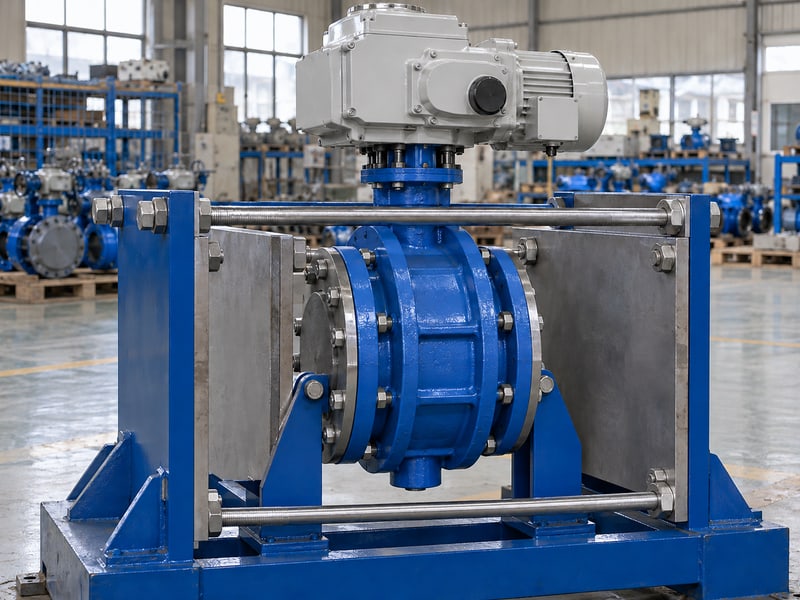
A motorized butterfly valve specification should define the agreed dimensional, pressure, leakage, material, and functional acceptance checks for the offered configuration. State the applicable methods and acceptance criteria rather than requesting a generic passed test. Keep proof-test conditions distinct from permitted working ratings and from process-performance acceptance.
Which acceptance fields prevent ambiguity?
Identify the condition and the result required. Specify the test procedure, medium, pressure, direction, duration, leakage criterion, and records where applicable. Define command, indication, and failure-response checks according to the accepted control design, with witness or hold points assigned through the project inspection plan.
- Identify each required check and its governing procedure.
- State acceptance criteria, evidence, and review responsibilities.
- Define corrective work, retesting, and release conditions.
How should conformity evidence be requested?
Key takeaway: Request evidence covering the actual supplied model and project scope. Management-system documents, product or application approvals, and unit inspection records answer different questions, so list the applicable requirements and their coverage separately.
| Acceptance field | Blank input |
|---|---|
| Required checks and criteria | [enter procedures, conditions, and limits] |
| Records and witness points | [enter evidence and inspection responsibilities] |
| Release and retest rules | [enter agreed conditions and decision owner] |
Complete the acceptance schedule before testing starts. Resolve unavailable evidence or proposed exceptions before release.
10. How do you close motorized butterfly valve specification gaps?
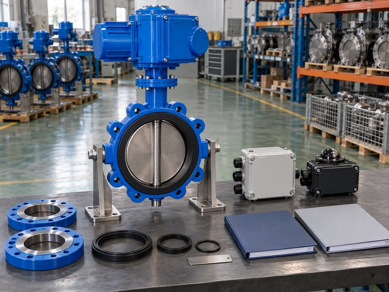
A motorized butterfly valve specification gap is closed when the responsible reviewer supplies an input or accepts a documented supplier response and updates the governing configuration. Keep unanswered requirements distinct from proposed deviations. A technically acceptable exception must follow the order into drawings, inspection criteria, and operating documents where it affects them.
What should you send for a technical review?
Submit the datasheet and its open items together. RUITO can review configurations and provide model-specific drawings, operating data, material information, and project inspection documentation. Use the technical inquiry form to send the service cases, interface requirements, control schedule, and identified gaps as one review package.
- Assign an owner and required response to each missing input.
- Compare requested and offered details in a deviation register.
- Record acceptance conditions and update affected document revisions.
What completes the accepted specification?
Key takeaway: Close the datasheet with identifiable requirements, evidence, and decisions. For configuration and documentation review, contact us today with your draft specification and the questions that remain unresolved.
| Closure field | Blank input |
|---|---|
| Missing input or deviation | [enter issue, owner, and response] |
| Review decision | [enter acceptance or required correction] |
| Governing update | [enter affected files and accepted revision] |
Release the order against the accepted package. Reopen the review when service or configuration changes.
FAQ
Q1: Can I specify only size and nominal pressure class?
No. Include actual service conditions, closing differential, interfaces, materials, actuator functions, and the required acceptance scope.
Q2: What's the best way to write a fail-safe requirement?
Name the event and required response. Separate command loss from power loss and request confirmation of the proposed arrangement's capability.
Q3: Can I leave unknown datasheet fields blank?
Yes, during review if you identify their owners and status. Resolve the inputs or accept documented assumptions before releasing the affected configuration.
Q4: Does a mounting-standard reference prove compatibility?
No. Reference the accepted mounting, drive, and assembly drawings so the complete proposed interface can be confirmed.
Q5: How do I accept a supplier's proposed deviation?
Review its technical effect and record the decision. Carry accepted exceptions into the datasheet and every affected governing document.