
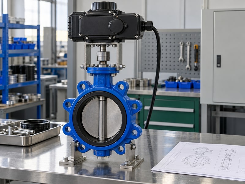
Fix motorized butterfly valve flow control errors by matching the valve's flow characteristics with system demand, measuring the controlled process, and respecting approved operating limits. A halfway position can still produce the wrong flow. Use model-specific capacity data, process measurements, and a defined commissioning plan before adjusting control settings.
1. What is motorized butterfly valve flow control?
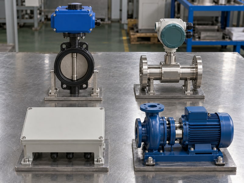
Motorized butterfly valve flow control regulates a process by changing disc position through an approved electric drive and control arrangement. The disc changes resistance to flow while the surrounding system supplies the pressure difference. Whether the loop achieves its target depends on valve capacity, available pressure, measurements, and operating conditions.
Which process result should you define?
Name the controlled variable. A flow loop aims to maintain measured flow, while a temperature loop may manipulate flow to maintain temperature. State which result your system needs, what disturbances it must accommodate, and whether continuous modulation is permitted for the selected valve and actuator.
- Identify the target variable and measurement location.
- State required minimum, normal, and maximum operating flow.
- Define the permitted control mode and safe operating constraints.
What belongs in the control description?
Key takeaway: Describe the process objective before specifying an opening command. Include the measurement, controller, valve response, and required protective actions so engineering can check the complete loop rather than a valve position in isolation.
| Loop element | Defined role |
|---|---|
| Process measurement | Reports the controlled result |
| Controller | Determines the requested correction |
| Valve and drive | Change resistance within approved limits |
Record the process objective with its operating cases. Confirm that the selected assembly permits the proposed duty.
2. Does motorized butterfly valve flow control follow disc angle?
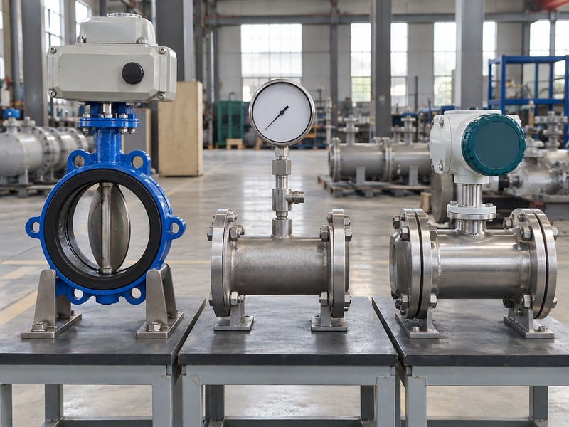
Motorized butterfly valve flow control does not normally produce a flow percentage equal to its opening percentage. Disc geometry affects capacity, and pressure difference changes as the system operates. A halfway travel indication cannot establish half of the design flow, even when the position measurement is accurate.
What changes when the surrounding system changes?
Compare position with measured flow. At a fixed disc position, a pump-speed change or a different arrangement of open branches can alter available pressure and flow. For HVAC and district energy circuits, review those changing network conditions rather than assigning one permanent flow value to each position.
- Use the exact model's capacity-versus-opening information.
- Record pressure conditions when comparing position and flow.
- Check system response when pumps or neighboring branches change.
How should a percentage display be labelled?
Key takeaway: Label travel percentage as valve position unless a separate process measurement supports a flow indication. Keep measured flow and position as distinct values in the control display so operators can identify a changing system response.
| Displayed value | Meaning |
|---|---|
| Position percentage | Indicated mechanical travel |
| Flow reading | Measured process flow |
| Capacity at an opening | Model-specific reference information |
Check the display's scaling and labels. Remove assumptions that turn a travel indication into an unverified flow reading.
3. What data sizes motorized butterfly valve flow control?

Motorized butterfly valve flow control sizing needs model-specific Cv or Kv information across the proposed openings, together with system flow, pressure, and fluid data. Full-open capacity alone cannot show whether the assembly can regulate small changes at the required operating points. Review the range of conditions the loop will encounter.
How should capacity information be applied?
Use one consistent sizing basis. Cv and Kv describe capacity using different unit conventions, so identify which basis the supplied data uses. Apply the appropriate sizing method for the fluid and conditions; gas, viscous liquid, or conditions involving phase change need the relevant treatment rather than an uncorrected water-based calculation. For applicable control-valve calculations, IEC 60534-2-1 provides sizing equations that account for installed conditions.
- Obtain capacity data for the exact size and disc configuration.
- Provide fluid properties and pressure conditions at each operating case.
- Check useful control response throughout the proposed opening window.
What should the sizing review establish?
Key takeaway: Select for the required regulating cases as well as maximum capacity. If most process adjustment occurs over a very small movement, review sizing and the installed response before trying to solve the problem through controller tuning alone.
| Sizing input | Purpose |
|---|---|
| Capacity versus opening | Describes available regulation |
| Required flow cases | Defines process demand |
| Pressure and fluid data | Supports the applicable calculation |
Request the missing operating cases before accepting the selection. Keep the sizing basis with the approved process description.
4. What limits motorized butterfly valve flow control pressure?
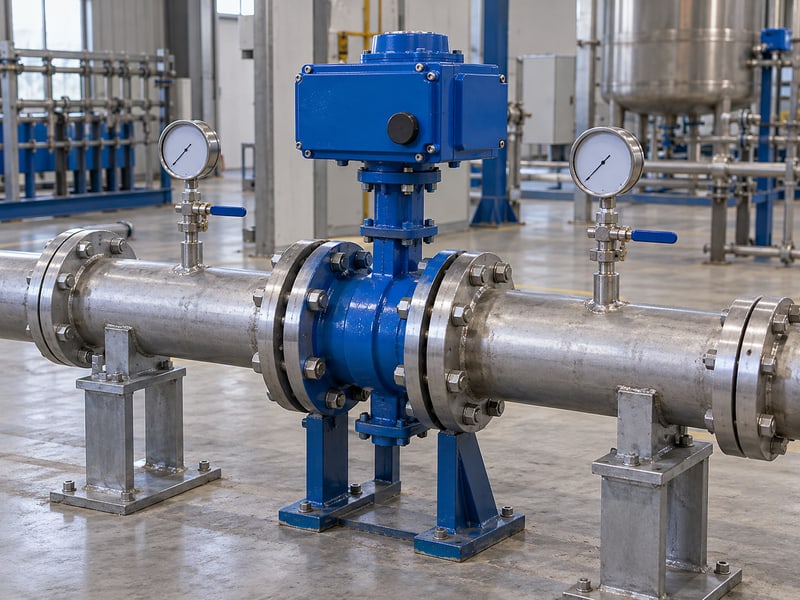
Motorized butterfly valve flow control is limited by the assembly's operating envelope and the pressure conditions needed for stable regulation. Line pressure, pressure difference across the disc, and fluid temperature answer different questions. A nominal body rating cannot establish that continuous throttling at a particular differential pressure is acceptable.
Which pressure conditions need review?
Check each operating case together. Include inlet and outlet conditions, permitted temperature, available differential, and the proposed opening. For a flanged butterfly valve, confirm the exact disc and seat design's operating limits instead of applying one rating across all flanged configurations.
- Review insufficient available differential at required high flow.
- Check permitted differential, torque, and velocity during regulation.
- Assess cavitation, flashing, choking, or noise where applicable.
How should pressure restrictions enter the control logic?
Key takeaway: Define pressure-related restrictions using the accepted selection review. Low outlet pressure or abnormal differential may require a specific protective response, and that response must fit the process hazard review rather than relying on an assumed fully open or fully closed action.
| Pressure information | Review purpose |
|---|---|
| Line pressure and temperature | Assembly operating rating |
| Valve differential | Capacity and mechanical load |
| Outlet conditions | Phase behavior and process limits |
Document the accepted restrictions for each case. Have the responsible process engineer approve the corresponding protective actions.
5. What feedback suits motorized butterfly valve flow control?
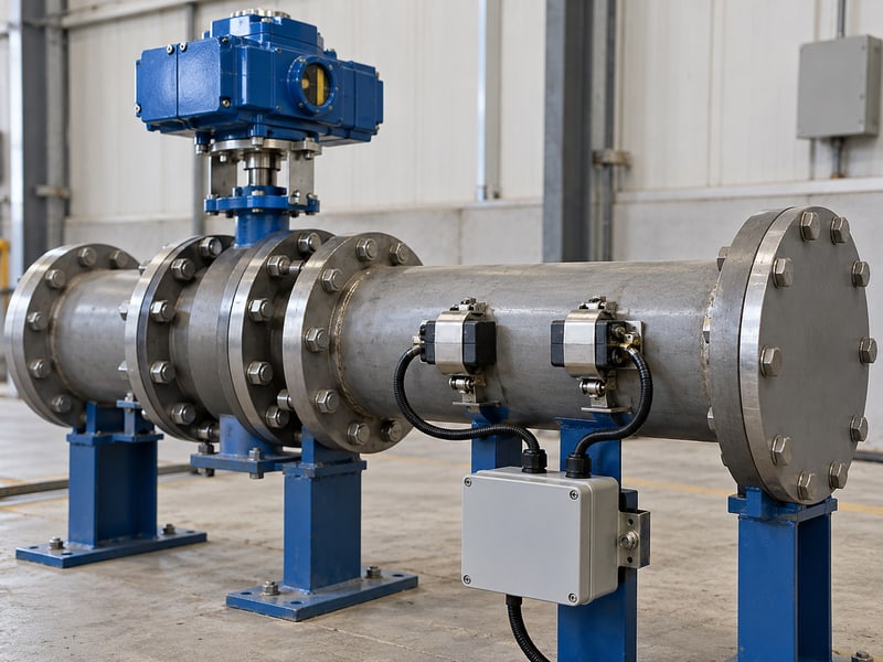
Closed-loop motorized butterfly valve flow control needs feedback that represents the controlled process, with position feedback used to check whether the valve follows its command. A position signal can describe travel while flow remains wrong because pressure or another system condition changed. The controller must receive the measurement appropriate to its stated objective.
How do you distinguish feedback roles?
Keep the signal meanings separate. A flow transmitter reports measured flow, while an actuator position output reports its configured position reference. Check sensor placement, calibration, engineering units, and signal scaling before interpreting a disagreement as a valve fault or changing the controller response.
- Verify that the process sensor measures the intended stream.
- Confirm command and position signals use the accepted scaling.
- Check measurement validity and documented signal-loss behavior.
What does a three-signal comparison reveal?
Key takeaway: Trend command, position, and process measurement together. Their timing can help distinguish a drive that fails to follow commands from a valve that moves correctly while the process cannot reach its target under current conditions.
| Signal | Question answered |
|---|---|
| Command | What movement was requested? |
| Position | Did the indicated travel follow? |
| Process feedback | Did the controlled result respond? |
Confirm each signal's meaning before commissioning. Retain a common time reference for diagnostic trends.
6. Which commands suit motorized butterfly valve flow control?
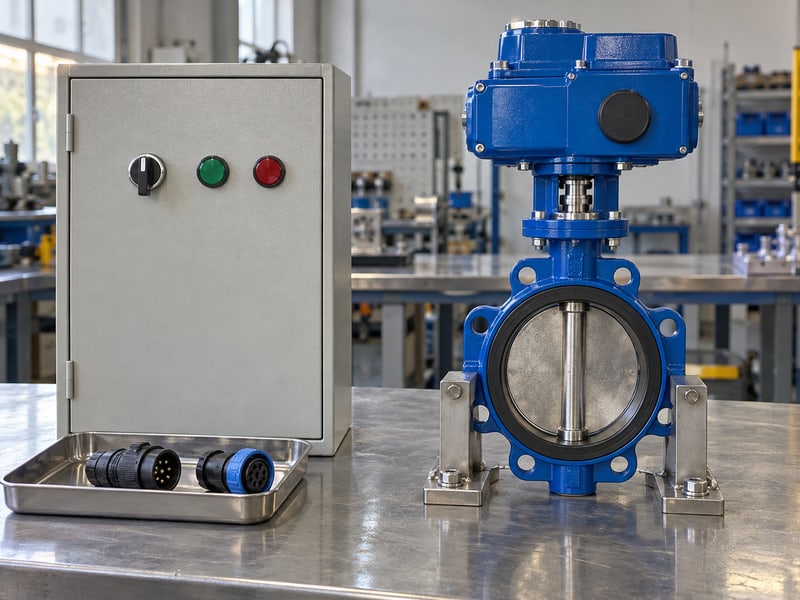
Motorized butterfly valve flow control should use only commands supported by the approved actuator and control design. An analog or network interface can request position when configured for that function, while a simple open-close arrangement may offer different capabilities. The presence of terminals or a communication option does not establish the intended process behavior.
What should the interface review confirm?
Check the approved signal path. Match command type, scaling, direction of action, and local or remote selection with the electrical documents. For a current-loop interface, use sourcing or sinking arrangements only when the approved input-output specifications support them; connection details belong in the model's wiring instructions.
- Confirm which device generates and which device receives the command.
- Define scaling, limits, interlocks, and operating-mode priority.
- Verify approved responses to signal loss and power loss separately.
How should command limits be implemented?
Key takeaway: Apply software limits within the accepted mechanical and process operating window. A controller limit cannot authorize an unsuitable throttling position, and a manual command should follow the same process restrictions unless an approved procedure defines another controlled mode.
| Command detail | Required confirmation |
|---|---|
| Signal interface | Compatible approved devices |
| Scaling and action | Correct requested position |
| Loss response | Documented process behavior |
Verify the interface through an authorized commissioning procedure. Record the accepted control settings and revision.
7. What duty suits motorized butterfly valve flow control?
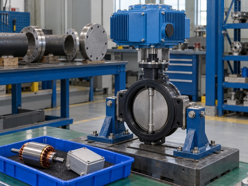
Motorized butterfly valve flow control requires a valve and actuator approved for the expected modulation frequency, operating time, load, and environment. An assembly selected for occasional isolation may be unsuitable for repeated small corrections. Analog positioning capability alone does not establish continuous regulating-duty suitability.
Which operating demands should you describe?
Describe the movement the process will request. Include expected starts, reversals, travel per correction, torque, ambient conditions, and sustained operating periods. Ask for the applicable actuator duty limits and any restrictions on the valve's throttling service rather than applying a generic duty percentage to every assembly.
- Match expected modulation with the specified actuator duty rating.
- Review valve seat, disc, and shaft suitability for the process.
- Check operating speed against control needs and transient constraints.
How do you manage excessive control activity?
Key takeaway: Repeated movement should remain within the accepted duty and process limits. Review the cause of excessive corrections before widening deadband or slowing movement, since those adjustments can reduce activity while allowing unacceptable process variation.
| Duty factor | Information needed |
|---|---|
| Movement frequency | Expected starts and reversals |
| Mechanical demand | Torque and travel conditions |
| Operating environment | Ambient and service limitations |
Confirm the permitted duty before enabling automatic operation. Record any constraints in the operating procedure.
8. Why does motorized butterfly valve flow control hunt?
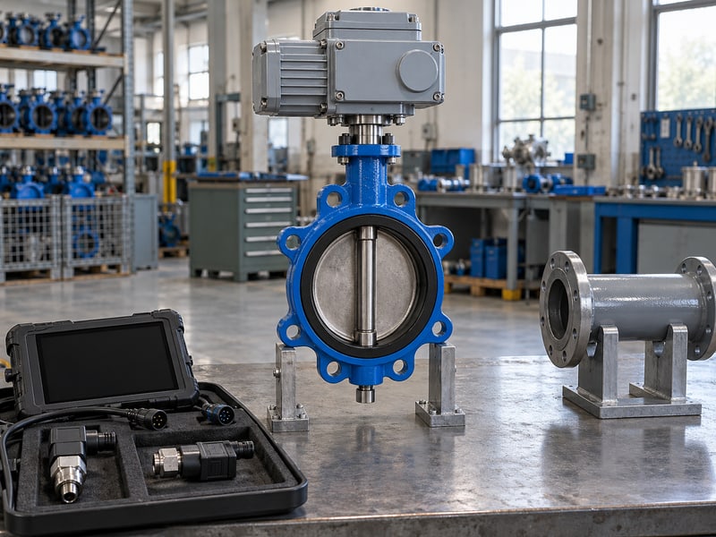
Motorized butterfly valve flow control can hunt when the loop repeatedly overcorrects or reacts to an unstable measurement, changing pressure, or irregular valve response. Cycling alone does not identify its cause. Examine the relationships between command, position, process value, and pressure before changing mechanical parts or tuning parameters.
What sequence helps narrow the cause?
Separate measurement, movement, and process response. If the indicated position follows a cycling command, review measurement quality, controller action, and changing system conditions. If command changes produce delayed or uneven movement, investigate the drive and valve response within the site's authorized diagnostic and maintenance procedures.
- Verify sensor scaling, timing, and measurement quality.
- Compare command and position for delay or lost response.
- Correlate flow changes with pressure and other equipment operation.
How should corrective work be accepted?
Key takeaway: Change one reviewed cause at a time and compare the result against the process criteria. Hardware adjustment requires the applicable isolation procedure, while controller changes require process authorization and a record of the previous settings.
| Observed pattern | Review focus |
|---|---|
| Command and position cycle together | Loop demand and tuning |
| Position fails to follow | Drive or valve response |
| Flow changes at stable position | Pressure, measurement, or system state |
Capture trends before adjusting the loop. Stop the test if approved operating limits are approached.
9. How do you accept motorized butterfly valve flow control?
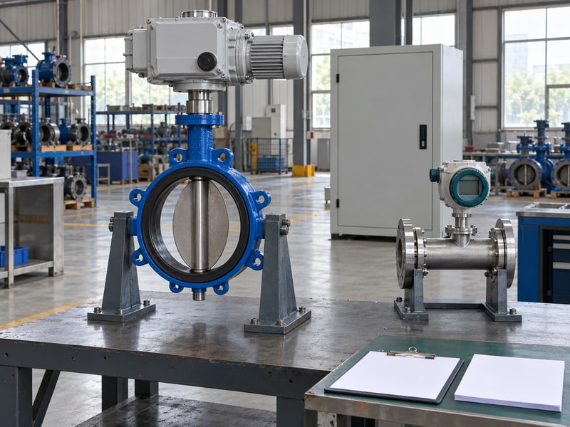
Motorized butterfly valve flow control should be accepted against defined process performance and operating constraints across the agreed test cases. A successful full stroke confirms movement but cannot establish stable regulation. Specify the permitted deviation from target, response requirements, and test conditions before commissioning begins.
Which tests demonstrate the intended behavior?
Test the process objective under controlled conditions. Review steady operation, authorized target changes, and relevant disturbances within the approved window. Where a hydronic circuit includes static balancing valves, retain their accepted settings and measurement basis so the regulation test starts from a known network condition.
- Verify measurement, command scaling, and position indication.
- Test agreed operating cases and permitted disturbance responses.
- Check protective behavior through the approved test method.
What should a commissioning record include?
Key takeaway: Record the conditions that support each accepted result. Include flow, relevant pressure and temperature, controller settings, valve position, and unresolved restrictions so a later system change does not inherit an acceptance claim outside its tested basis.
| Acceptance item | Defined evidence |
|---|---|
| Target tracking | Permitted deviation and response |
| Stability | Agreed trends and test conditions |
| Operating constraints | No breach of approved limits |
Close unresolved findings before routine automatic operation. Retain the accepted settings with the commissioning record.
10. What defines motorized butterfly valve flow control's window?
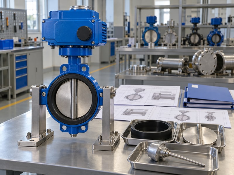
Motorized butterfly valve flow control's operating window is defined by the selected assembly's approved throttling limits and the process conditions it can regulate acceptably. It includes flow demand, pressure differential, fluid properties, temperature, opening, and actuator duty. Use that combined review instead of assigning every butterfly valve the same permitted travel band.
What inputs define motorized butterfly valve flow control?
Bring the operating cases together. RUITO can review valve configurations and provide model-specific operating data, capacity information, torque requirements, and relevant drawings. Supply minimum, normal, and maximum demand with the corresponding pressure conditions so the selected valve can be reviewed for the intended regulating service.
- Fluid composition, temperature, flow cases, and pressure conditions.
- Process objective, measurement arrangement, and expected modulation.
- Required operating window, acceptance criteria, and protective actions.
What should the accepted review deliver?
Key takeaway: Request documented limits and the data used to establish them. For configuration and operating-data review, contact us today with your flow cases, pressure conditions, and control requirements.
| Review input | Requested output |
|---|---|
| Process cases | Capacity and suitability review |
| Assembly selection | Model-specific limits and data |
| Control requirements | Operating window and restrictions |
Have the responsible system engineer approve the final window. Update it when operating conditions or the assembly change.
FAQ
Q1: Can I use halfway travel as half of full flow?
No. Disc geometry and system pressure affect flow, so use model-specific capacity data and a separate process measurement.
Q2: What's the best feedback for a flow-control loop?
Use an appropriate flow measurement. Position feedback checks commanded travel but does not establish the actual flow through the system.
Q3: Can any electric butterfly valve modulate continuously?
No. Confirm the exact valve's regulating suitability and the actuator's approved duty, load, movement frequency, and environmental limits.
Q4: How do I know why my control loop keeps cycling?
Compare synchronized command, position, process, and pressure trends. Check measurement quality and movement response before making authorized tuning or hardware changes.
Q5: Is there one preferred opening range for every butterfly valve?
No. Establish the permitted window from model-specific data, service conditions, actuator limits, and the required process performance.