
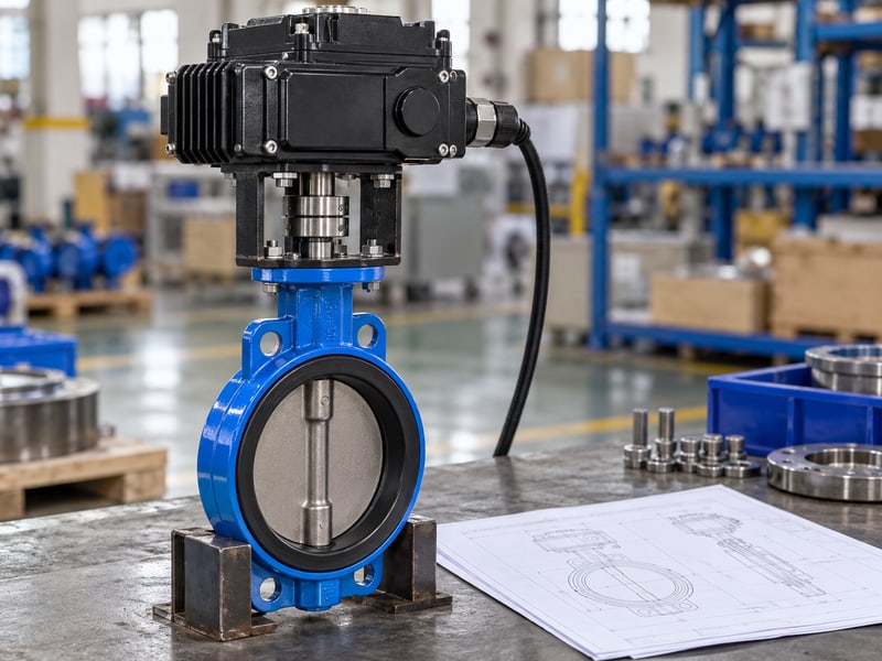
Fix motorized wafer butterfly valve mistakes by confirming the companion flanges, disc clearance, installed length, sealing arrangement, and support before applying power. A compact body can match the bolt pattern yet bind after clamping. Compare the selected assembly with measured pipe interfaces and its installation instructions before committing the shutdown.
1. What fits a motorized wafer butterfly valve?
A motorized wafer butterfly valve fits when its body, disc envelope, sealing faces, fasteners, and drive clearance match the approved piping arrangement. Motor operation does not correct an incompatible pipe interface. Verify the complete installed envelope alongside the valve's working and directional shutoff limits.
Which dimensions belong in the purchase review?
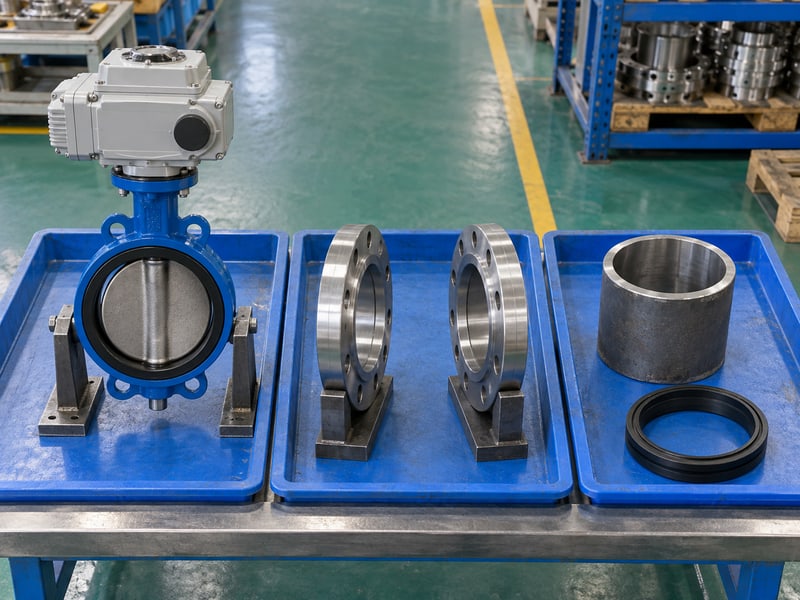
RUITO's wafer butterfly valve configurations need size-specific drawings for face-to-face length, bore clearance, and bolting. Request the supplied assembly's drawing and installation, operation, and maintenance manual, or IOM. Include the existing spool and companion flange details so the review uses the actual interface.
- Identify the body, seat, and drive configuration.
- Provide measured pipe and companion flange details.
- Request disc and external assembly envelopes.
Compare the installed package with the pipe. An electric drive adds weight and external space requirements without increasing body pressure capability. Confirm pressure-temperature limits, permitted pressure direction, and maximum closed differential independently of the motor selection.
What should procurement retain?
Keep approved drawings, working limits, instructions, and deviations with the valve tag. Retain the same configuration through delivery review. Key takeaway: approve mechanical fit and service limits together for the supplied wafer package.
| Review item | Evidence |
|---|---|
| Pipe interface | Measured companion details |
| Moving envelope | Model drawing |
| Service limits | Working and directional ratings |
Close dimensional gaps before releasing the purchase order.
2. Which flanges fit a motorized wafer butterfly valve?
A motorized wafer butterfly valve needs companion flanges compatible with its specified drilling, face form, bore, and sealing instructions. Nominal diameter or a familiar pressure-class label cannot establish all those conditions. Review the actual flange construction on each side of the body.

What should the flange comparison include?
Identify the applicable flange specification, drilling, face type, and pipe connection geometry. Similar bolt circles can coexist with different face forms or internal openings. Check both sides, particularly where a replacement joins older pipework to a newly fabricated spool.
- Match the documented flange specification and drilling.
- Verify face form and sealing-surface condition.
- Compare actual bore geometry near the disc.
Check the flange face as well as its holes. A bolt-pattern match does not establish that the valve's seat can seal against the offered face. Obtain the model's companion flange requirements before accepting an existing or proposed flange arrangement.
How should a mismatch be resolved?
Resolve incompatible flanges through project engineering. Review clearance, length, sealing, and loads for any revised spool or adapter. Key takeaway: companion flange compatibility requires the complete interface.
| Flange feature | Check |
|---|---|
| Drilling | Correct bolt arrangement |
| Face form | Approved sealing contact |
| Internal opening | Disc sweep clearance |
Attach companion flange drawings to the valve submittal.
3. What bore clears a motorized wafer butterfly valve?
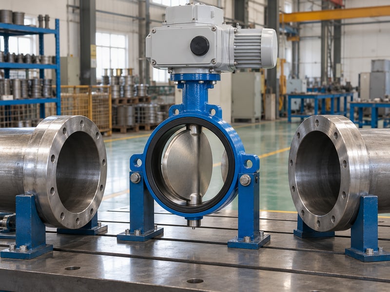
A motorized wafer butterfly valve needs a pipe and flange opening that clears its full required disc sweep. The disc can project beyond the short body during rotation. Closed-position fit alone cannot establish clearance throughout movement.
Where can interference occur?
Check flange shoulders, pipe linings, weld penetration, adjacent reducers, and nearby internal components. Their location relative to the valve face affects the available opening. Use the model's disc envelope and actual internal geometry rather than treating the pipe's nominal size as its measured clearance.
- Review both upstream and downstream disc projections.
- Include linings, sleeves, and internal weld features.
- Check adjacent component envelopes across required travel.
Measure where the disc moves. Checking only the closed-disc position can miss an obstruction beyond either body face. Compare the complete swept envelope with the assembled pipe opening before relying on a powered movement check.
What if the opening is too small?
Stop and obtain an approved interface correction. Do not grind the disc, trim a liner, or increase drive force to pass an obstruction. Key takeaway: full disc clearance is a dimensional acceptance requirement that must be resolved before energizing the assembly.
| Internal feature | Verify |
|---|---|
| Flange bore | Swept disc clearance |
| Lining or weld | Actual local opening |
| Adjacent equipment | No envelope conflict |
Record measured bore clearances against the valve tag.
4. What length fits a motorized wafer butterfly valve?
A motorized wafer butterfly valve needs an installed flange gap compatible with its approved face-to-face length and sealing arrangement. A compact body still requires controlled insertion space. Incorrect spool length or forced pipe displacement can load the valve and distort the joint.

Which length should the fitter use?
Use the drawing for the actual body, seat, and nominal size. Confirm whether specified gaskets affect the joint arrangement and follow the model's insertion instructions. Do not substitute a length from another body style or a generic catalogue illustration.
- Measure the prepared spool gap.
- Confirm the supplied face-to-face dimension.
- Include the specified sealing and insertion requirements.
Prepare the gap without pulling the pipe against the valve. Flange bolts should secure an aligned joint rather than correct an incorrect spool. Review supports and any permitted installation adjustment before bringing the faces together.
How should dimensional acceptance be recorded?
Retain the measured gap, approved length, and accepted adjustments. Check that clamping preserves centering and drive access. Key takeaway: correct installed length preserves the prepared alignment and sealing condition.
| Length detail | Verify |
|---|---|
| Spool gap | Compatible prepared opening |
| Body length | Exact model drawing |
| Joint arrangement | Specified seals and faces |
Confirm the prepared gap before the lifting crew inserts the valve.
5. How is a motorized wafer butterfly valve centered?
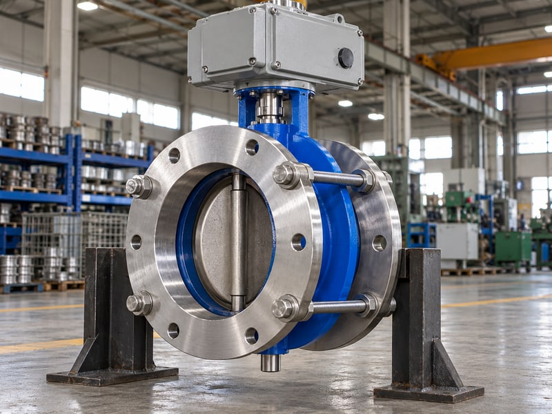
A motorized wafer butterfly valve is centered using the model's prescribed locating method between aligned, supported companion flanges. Casting shape or locating ears do not guarantee automatic centering in every arrangement. Keep the disc envelope and sealing faces aligned while clamp load increases.
What should be checked before tightening?
Confirm that flange faces are parallel and the pipe is supported without forced displacement. Follow the prescribed disc position and handling method during insertion. Protect the seat and sealing faces from scraping as the body enters the prepared opening.
- Use the specified body locating features or guides.
- Keep support loads on approved points.
- Verify body position and disc clearance before clamping.
Check centering before increasing clamp load. A body that shifts during installation can reduce clearance even when the original dimensions were suitable. Inspect alignment at the stages required by the model instructions instead of assuming the bolts will center it.
What should be done if alignment changes?
Stop and resolve the support, locating, or pipe-fit condition through the approved procedure. Do not compensate for visible misalignment by increasing tightening force. Key takeaway: retain body centering through staged assembly so dimensional clearance survives final installation.
| Alignment item | Acceptable finding |
|---|---|
| Companion faces | Parallel and aligned |
| Body position | Prescribed centering achieved |
| Disc envelope | Required clearance retained |
Record the centering check before final joint acceptance.
6. Which seals suit a motorized wafer butterfly valve?
A motorized wafer butterfly valve needs the seat, liner, and gasket arrangement specified for its exact construction. Some resilient designs seal directly against companion flanges; other arrangements require specified separate gaskets. Neither a universal no-gasket rule nor routine gasket addition is appropriate.
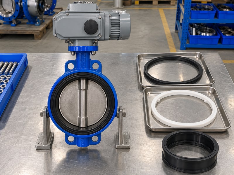
How should the sealing arrangement be reviewed?
Confirm companion face requirements, separate gasket instructions, permitted lubricants, and sealing-surface preparation. Check actual fluid composition and temperature against the offered materials. EPDM water-service seating cannot be assumed suitable for mineral oil or steam simply because the body is motor operated.
- Identify seat and liner construction.
- Confirm any required gasket type and placement.
- Inspect sealing faces for damage or debris.
Use the specified sealing arrangement. RUITO's PTFE lined butterfly valve options also require review of liner flares, backing, and shaft seals. Apply the model's clamping instructions rather than another valve's gasket practice.
What should commissioning distinguish?
Separate flange leakage, shaft leakage, and leakage across the closed disc when recording a fault. Investigate after safe isolation through the applicable service procedure. Key takeaway: correct sealing depends on the configured materials, companion faces, and controlled joint compression together.
| Sealing item | Model-specific check |
|---|---|
| Seat or liner | Fluid and temperature suitability |
| Separate gasket | Required arrangement |
| Companion face | Permitted contact geometry |
Resolve gasket and liner questions before final bolting.
7. What bolts fit a motorized wafer butterfly valve?
A motorized wafer butterfly valve needs fasteners that suit its companion flanges, body clearance, and specified clamping arrangement. Wafer connections commonly use bolts or studs spanning the flange pair. The exact grade, length, fit, and tightening values come from the approved joint requirements.
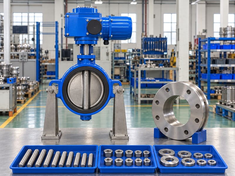
What should the bolt review include?
Confirm bolt path, nut and tool access, adequate engagement, and clearance from the body and drive. Check the assembled joint rather than selecting length from nominal valve size alone. Avoid assuming that a locating feature is a threaded fastening lug or an approved lifting point.
- Match fastener dimensions and grade with the specification.
- Confirm body and operator clearances.
- Follow the prescribed tightening sequence and stages.
Use the approved joint's tightening values. Seat construction, flange details, sealing arrangement, and fastener conditions affect the instructions. A generic bolt chart cannot replace the valve and joint requirements for the installed configuration.
What should the installer retain?
Record fastener completion and the required intermediate fit or movement checks. Inspect for body displacement as clamping proceeds. Key takeaway: correct fastener fit and controlled tightening preserve the wafer body's centering, sealing contact, and disc clearance.
| Fastener detail | Verify |
|---|---|
| Length and engagement | Complete joint fit |
| Bolt path | Body and drive clearance |
| Tightening method | Approved values and sequence |
Keep the bolting record with the installation inspection.
8. What supports a motorized wafer butterfly valve?
A motorized wafer butterfly valve needs an approved support arrangement for the pipe, valve, and attached drive loads. A short body does not eliminate those loads. Drive weight and location can create a moment that the mounting and support design must address.

Which installed loads should be reviewed?
Provide the assembled mass, drive location, proposed supports, and required service clearances. Include operating reactions and pipe movement where relevant to the project. Supports must use approved structural points rather than an improvised restraint against a shaft, service cover, or accessory.
- Identify pipe and assembly support points.
- Show the drive's weight and location.
- Reserve access for maintenance and removal.
Review the load path with the finished layout. Insulation, cable trays, guards, and platforms can affect access and proposed support. Keep the support arrangement consistent with the piping design's permitted thermal movement and connection loads.
How should a restricted layout be resolved?
Submit the installed elevation and support detail. Resolve unsupported side loads and blocked removal paths during review. Key takeaway: compact pipe length still requires controlled loads and external service clearance.
| Installed concern | Required review |
|---|---|
| Pipe loading | Support and connection limits |
| Drive weight | Approved load path |
| Service access | Removal and inspection envelope |
Approve the support detail before completing adjacent work.
9. Can a motorized wafer butterfly valve serve a pipe end?
A motorized wafer butterfly valve needs explicit model and retention approval for any proposed end-of-line duty. Ordinary between-flange installation must not be assumed to permit downstream flange removal under pressure. Motor operation supplies no additional end-of-line rating or retention capability.

What must the maintenance scenario state?
Describe which pipe and flange components remain installed, the pressure direction, temperature, and maximum differential. Confirm how the valve is retained and supported in that exact condition. Do not transfer a rating for a fully connected assembly to a different maintenance arrangement.
- Define the proposed disconnected condition.
- Request the model's permitted retention arrangement.
- Verify working and directional differential limits.
Treat flange removal as a separate duty review. If maintenance requires independent one-sided bolting, review suitable alternatives such as RUITO's lug butterfly valve configurations. Their own end-of-line permission also depends on the exact configuration and rated conditions.
What if approval is unavailable?
Use an approved isolation arrangement without relying on unverified end-of-line capability. Resolve maintenance requirements during body selection. Key takeaway: end-of-line duty requires documented permission for the actual retained assembly.
| Maintenance detail | Confirm |
|---|---|
| Remaining flanges | Approved retention |
| Applied pressure | Permitted direction and differential |
| Proposed alternative | Configuration-specific rating |
Include the maintenance disconnection scenario in the purchase specification.
10. How is a motorized wafer butterfly valve handed over?
A motorized wafer butterfly valve is handed over with documented mechanical fit, approved service limits, and accepted commissioning records. Verify installed clearance and movement before energizing it through the approved procedure. An actuator indicator alone cannot establish that the disc clears the pipe or seals correctly.

Which checks precede powered commissioning?
Confirm body direction, centering, sealing arrangement, fasteners, support, and disc clearance. Perform the model's required safe movement checks with personnel clear of the bore and drive. Accept mechanical fit before applying motor power. Stop and investigate abnormal resistance instead of increasing drive force or concealing interference with end settings.
- Retain measured interfaces and the final assembly drawing.
- Record required fit and movement verification.
- Follow approved functional and field-test limits.
What should operations receive?
Provide the model IOM, valve identification, working and directional limits, sealing instructions, bolting information, and accepted support details. Keep factory proof pressures separate from operating limits. Key takeaway: a reviewable handover joins measured pipe fit with the supplied configuration; contact us today with your flange drawings and valve requirements.
| Handover record | Purpose |
|---|---|
| Final drawing | Reproduce installed fit |
| Model instructions | Maintain the assembly |
| Acceptance records | Confirm completed checks |
Store the accepted installation package with the valve register.
Frequently asked questions
Q1: Can I select a wafer body by pipe diameter alone?
No. Confirm flange faces, bore clearance, installed length, sealing instructions, and service limits.
Q2: Do all wafer valves need separate gaskets?
No. Use the sealing arrangement required by the exact model and companion flanges.
Q3: Can I use motor torque to overcome binding?
No. Safely isolate and investigate centering, sealing compression, and disc interference before continuing.
Q4: Can I remove the downstream flange under pressure?
Only within an explicitly approved model and retention arrangement for that duty; never assume permission.
Q5: What's the best check before energizing the drive?
Verify documented mechanical fit and required unobstructed travel through the model's approved inspection procedure.