
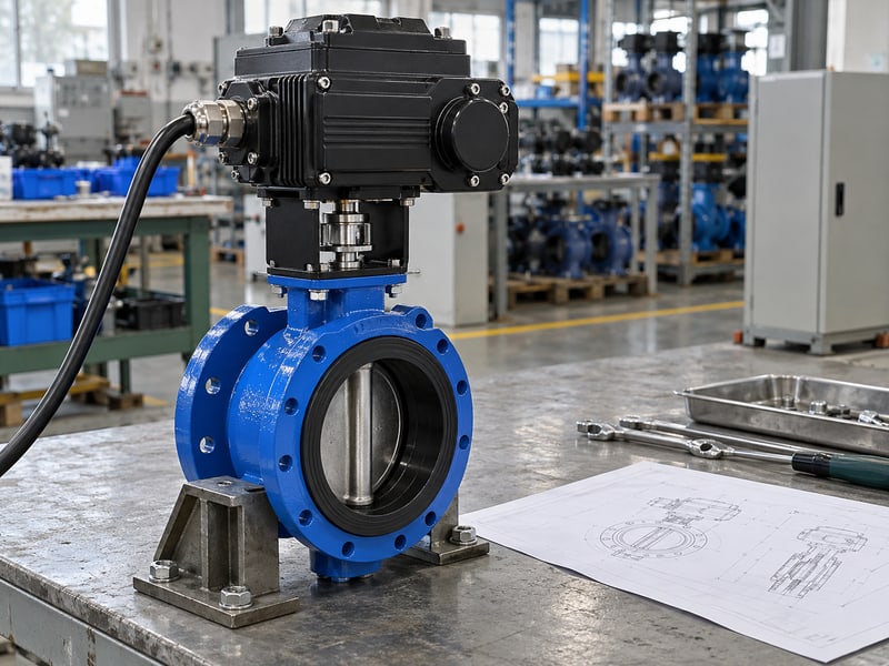
Fix motorized butterfly valve symbol mistakes by checking the project legend, valve tag, operator notation, and related control records together. A familiar graphic can hide a different drive type or an undefined failure response. Compare the current drawings and equipment schedule before approving procurement, wiring, or a field change.
1. What does a motorized butterfly valve symbol show?
A motorized butterfly valve symbol shows a butterfly valve and its motor-operated function according to the project's drawing convention. Additional marks or linked records may describe controls and operating states. The graphic alone cannot establish materials, pressure limits, motor voltage, or verified shutoff performance.

Which parts should you read separately?
Identify the valve representation, operator representation, tag, and signal connections. A piping and instrumentation diagram (P&ID) records process relationships. Read each component against its legend entry before inferring operation.
- Identify the body-type convention.
- Find the operator's legend entry.
- Follow the tag into the valve schedule.
Separate the valve from its operator. A drawing can represent an electric operator on several valve types. Confirm the butterfly body independently so a generic powered-valve graphic does not become an unintended ball, gate, or globe valve purchase.
What information belongs elsewhere?
Use the tagged datasheet for the selected body, wetted materials, working limits, and required drive function. Resolve gaps between that record and the P&ID through the project's document process. Key takeaway: read the graphic as one part of a tagged assembly record.
| Drawing element | Check against |
|---|---|
| Valve graphic | Body-type legend |
| Operator graphic | Drive convention |
| Tag | Equipment schedule |
Open the legend and tagged datasheet beside the P&ID.
2. How is a motorized butterfly valve symbol identified?
A motorized butterfly valve symbol is identified by matching its valve graphic with the approved project legend and confirming the tagged body type. Similar shapes can represent different devices in different drawing libraries. Screen appearance or memory of another project is insufficient evidence for a specification.
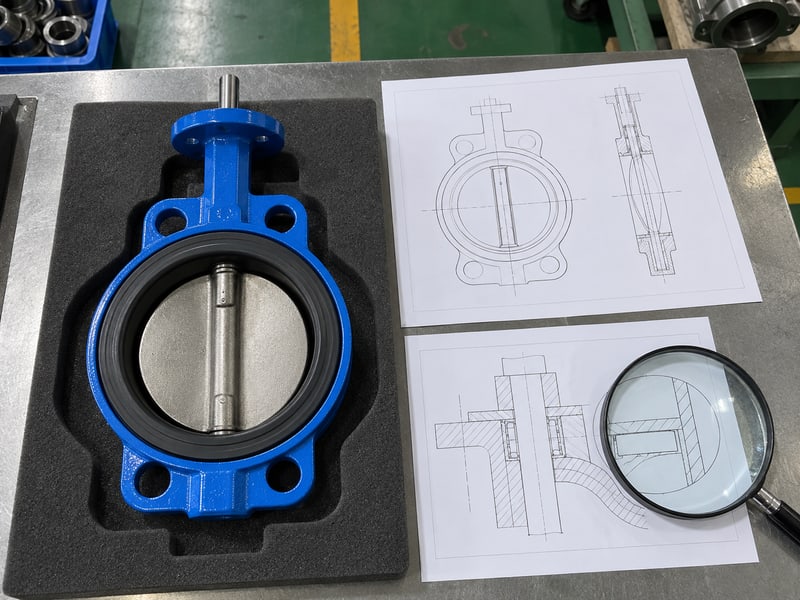
What if the symbol looks familiar?
Read the complete legend description, including subtypes or qualifiers. A reduced-scale PDF can obscure a small marker. Inspect a legible controlled copy.
- Verify the legend belongs to the same drawing set.
- Check small distinguishing marks at readable scale.
- Confirm the valve type in its schedule entry.
Verify the legend before copying a graphic. Reusing a CAD block can carry attributes that differ from its visible shape. Check attached data, tag fields, and library definitions where the project's authoring system uses them.
Does the symbol identify the connection style?
Only if the project convention and accompanying records say so. A wafer butterfly valve has installation interfaces that need dimensional confirmation regardless of its P&ID appearance. Key takeaway: verify body construction and connections from the tagged specification instead of guessing from the icon.
| Uncertainty | Resolve with |
|---|---|
| Similar valve shapes | Approved legend |
| Hidden block data | Controlled library attributes |
| Connection style | Datasheet and assembly drawing |
Raise a clarification if the graphic and schedule disagree.
3. Which operator fits a motorized butterfly valve symbol?
A motorized butterfly valve symbol should carry the project's approved notation for the specified motor operator. Confirm the operator's actual energy source and mechanism. An electrical command to a solenoid does not by itself mean an electric motor turns the valve shaft.
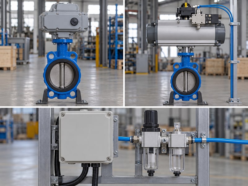
How do you distinguish command from motive power?
An air-operated valve can receive an electrical command while compressed air supplies its operating force. Check operator and utility requirements together so controls staff and procurement identify the same package.
- Identify the energy source that moves the valve.
- Check the operator description in the datasheet.
- Reconcile power or utility connections with that description.
Trace the operating energy separately from the command. A letter or box above a valve has meaning only within the adopted convention. If a project uses an “M” marker, verify that its legend defines the marker as the intended motor operator.
What should you confirm with the supplier?
Request the offered drive identification, assembled interface, supply requirements, and connection information. Avoid converting a generic automation note into an unreviewed drive choice. Key takeaway: represent the specified operating mechanism and distinguish it from the signal that commands movement.
| Detail | Question to resolve |
|---|---|
| Command | What requests movement? |
| Energy source | What produces movement? |
| Drive mechanism | What turns the shaft? |
Match the operator note with the quoted assembly before approval.
4. What tag belongs beside a motorized butterfly valve symbol?
A motorized butterfly valve symbol needs the unique tag assigned through the project's identification rules. The tag connects the P&ID with schedules, datasheets, control records, and site identification. Its letters and numbers should not be interpreted outside those rules.

Can a tag tell you the valve type?
Sometimes the naming convention includes body type or function, while another project records those fields separately. In a hypothetical example, “MOV-204” could identify a motor-operated valve where the project defines that prefix. The tag would still need a schedule entry identifying its butterfly body and supplied configuration.
- Check uniqueness within the applicable project scope.
- Match spelling and numbering across linked records.
- Keep functional identification separate from vendor model details.
Use one tag across the document package. A renamed valve can leave an obsolete identifier in electrical drawings or purchase schedules. Search the affected records and close those mismatches before the revised identifier reaches fabrication or commissioning.
What should the schedule contain?
Include body type, size, connection, materials, working conditions, drive duty, and document references in the linked records. Key takeaway: a consistent tag provides the route to the specification without requiring every attribute beside the graphic.
| Record | Match |
|---|---|
| P&ID | Assigned valve tag |
| Datasheet | Same assembly identifier |
| Electrical record | Same controlled reference |
Check the tag across process, mechanical, and electrical records.
5. How does a motorized butterfly valve symbol show control?
A motorized butterfly valve symbol shows control through the project's signal-line conventions, annotations, and referenced control documents. Those details should distinguish on/off operation from positioning duty. A remote command connection does not establish that the supplied drive supports continuous modulation.
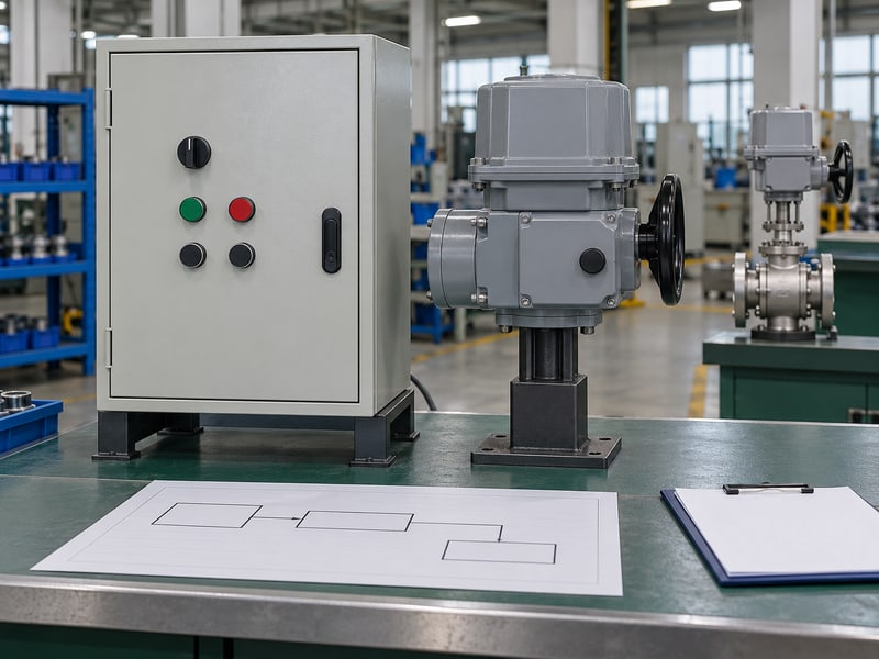
Which command information is needed?
Identify required open, close, stop, or position-demand functions. Confirm local/remote selection and permissives or interlocks. Reference implementation records where the P&ID omits details.
- Identify the command source and required functions.
- Reference applicable sequences and interlocks.
- Check the drive duty against intended positioning activity.
Keep process intent consistent with drive duty. An on/off motor package can be unsuitable for repeated short corrections even when a controller can send them. Resolve that mismatch through selection and control design rather than adding a modulation label to the drawing.
What does a signal line prove?
It represents the relationship defined by the project's line convention. Terminal assignments, signal format, wiring, and protocol belong in the applicable electrical or instrumentation records. Key takeaway: the P&ID should communicate control intent and lead reviewers to its implementation documents.
| Control detail | Verify in |
|---|---|
| Process function | P&ID and control narrative |
| Signal format | Signal schedule |
| Terminal assignment | Connection drawing |
Add a document reference wherever the control intent needs detail.
6. What feedback suits a motorized butterfly valve symbol?
A motorized butterfly valve symbol should show or reference the feedback needed for its specified operating function. End-position status, intermediate position, and fault alarms provide different information. A displayed closed status cannot establish seat tightness or measured flow through the valve.
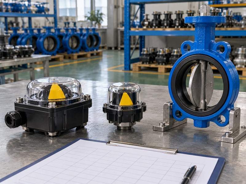
Which feedback distinctions should remain visible?
Separate commands from returned status. Identify the device that supplies each end signal. For positioning duty, define the position return and response to disagreement, missing signals, or faults.
- Distinguish requested state from reported state.
- Specify needed end-position or intermediate feedback.
- Identify alarms that operations staff must receive.
Label what the feedback can establish. An end switch reports the condition defined by its installed mechanism and settings. Verify correspondence with actual disc travel during commissioning, then assess shutoff through the valve's separate approved acceptance procedure.
How should the records be reconciled?
Compare P&ID annotations with the signal list, drive connection diagram, and commissioning plan. A spare terminal in a drawing does not establish that the required feedback device is included. Key takeaway: request feedback hardware and documented verification for every required operating indication.
| Information | Separate verification |
|---|---|
| Command | Requested movement |
| Position status | Verified travel indication |
| Shutoff performance | Approved seat test |
Check that the quoted drive includes the required feedback devices.
7. What fail note suits a motorized butterfly valve symbol?
A motorized butterfly valve symbol needs failure notation that defines the applicable event and matches the supplied assembly's response. Power loss, signal loss, and mechanical stalling can produce different outcomes. Motor operation alone does not establish fail-close or fail-open behavior.

How should normal and failure states be distinguished?
Define normal-state abbreviations through the legend and operating narrative. A normally open condition need not describe power-loss behavior. A filled graphic cannot replace an agreed failure description.
- Define the event behind each failure requirement.
- State the required stop, open, or closed response.
- Confirm any stored-energy equipment and readiness checks.
Name the failure event beside its required response. If the project uses “FO” or “FC,” verify the abbreviation and its conditions in the approved records. Confirm that drive selection, energy availability, and controls can meet the requirement under those conditions.
What should a reviewer refuse to infer?
Do not infer a safety certification, hazardous-area approval, or verified protective function from the glyph or a fail-position label. Those claims require their own applicable documentation. Key takeaway: failure notation records an engineered requirement whose implementation and verification remain separately controlled.
| Event | Record separately |
|---|---|
| Supply loss | Required assembly response |
| Signal loss | Configured control response |
| Mechanical stall | Protection and alarm |
Reconcile the failure matrix with the supplied drive documents.
8. What drawings verify a motorized butterfly valve symbol?
A motorized butterfly valve symbol is verified against its tagged process specification, general arrangement drawing, and electrical or instrumentation records. Each document answers a different part of the assembly question. Agreement across them should precede purchase, installation, and commissioning acceptance.
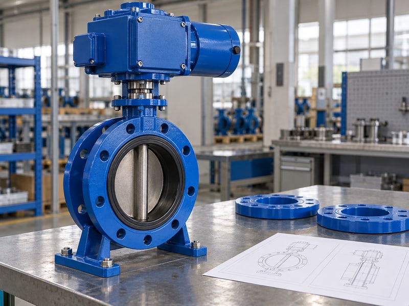
What does the mechanical drawing add?
The general arrangement (GA) supplies assembly dimensions and interfaces. For RUITO's flanged butterfly valve configurations, confirm body, face-to-face dimension, flange details, and disc clearance. P&ID symbols do not establish physical installation envelopes.
- Match connection and body details with the datasheet.
- Review drive, coupling, support, and service clearance.
- Confirm the offered directional shutoff and working limits.
Compare the same configuration in every drawing. A supplier drawing for another seat or drive can look sufficiently similar while carrying different dimensions or operating limits. Match identification and revision before using it for layout or electrical design.
What does the connection drawing add?
It identifies the supplied electrical interfaces and any configured accessories. Check supply, command, feedback, and fault provisions against the project's requirements. Key takeaway: the P&ID, GA, datasheet, and connection records must describe one agreed valve package.
| Document | Main check |
|---|---|
| P&ID | Process and control function |
| GA/datasheet | Assembly and service limits |
| Connection drawing | Supplied electrical interfaces |
Resolve cross-document discrepancies before releasing construction information.
9. How is a motorized butterfly valve symbol revised?
A motorized butterfly valve symbol is revised through the project's document and change procedures when its type, operator, tag, or function changes. The update must reach affected records beyond the P&ID sheet. A revised glyph alone cannot close an equipment or controls change.

Which changes should trigger a review?
Replacing a drive, changing duty, adding feedback, or revising failure requirements can alter several interfaces. A body or seat change can affect process suitability while leaving the operator symbol unchanged. Identify these changes explicitly so reviewers can assess their consequences.
- List affected drawings, schedules, and datasheets.
- Record the approved change and responsible reviewers.
- Identify which issued versions must be superseded.
Track the changed requirement through linked records. An added closed-status requirement may need hardware, wiring, software, and testing updates. Confirm each required deliverable before treating the new annotation as an implemented function.
How should field changes reach final records?
Capture approved field changes and verified supplier details during handover. Update final records for the accepted assembly. Key takeaway: revision control makes the operating record consistent with the equipment and its verified function.
| Changed item | Check affected records |
|---|---|
| Operator | Utilities and connections |
| Feedback | Hardware, signals, and tests |
| Tag or function | Schedules and control logic |
Attach the affected-document list to the change record.
10. Who approves a motorized butterfly valve symbol?
A motorized butterfly valve symbol is approved by the project's designated reviewers against its legend, tagged specification, and supporting records. Process, mechanical, and controls responsibilities should be clear. The valve supplier confirms the offered assembly information within its agreed scope.
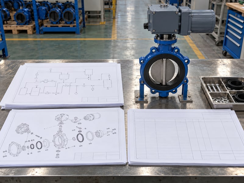
What should be checked before release?
Verify body type, motor operator, tag, operating intent, signals, and defined failure response. Confirm that document references lead to current records for the selected package. Close each discrepancy before drawing release. Unresolved items should remain assigned in the review record rather than disappear into a generic approval stamp.
- Confirm symbol and legend agreement.
- Reconcile process, mechanical, and electrical requirements.
- Retain revisions, clarifications, and acceptance responsibilities.
What can you send for an assembly review?
Send RUITO the tagged datasheet, legend extract, required drive function, and relevant layout and signal information. Request available assembly drawings, working limits, drive selection information, and installation documents for the offered configuration. Key takeaway: approve a traceable graphic and matching equipment record; contact us today with the tagged requirements.
| Release check | Evidence |
|---|---|
| Graphic meaning | Approved legend |
| Assembly identity | Tagged specification |
| Implemented function | Matching drawings and tests |
Keep the accepted document package with the valve register.
Frequently asked questions
Q1: Can I use an “M” marker on every project?
Only if its approved convention defines that marker for the intended motor operator.
Q2: How do I know a valve is a butterfly type?
Match the body graphic with the legend and confirm the tagged schedule entry.
Q3: Does a motor operator mean the valve fails closed?
No. Verify the specified event, required response, and supplied drive's failure behavior.
Q4: Can I measure installation space from a P&ID?
No. Use the current assembly and layout drawings for dimensions and clearances.
Q5: What's the best record for electrical connections?
Use the approved connection and wiring records for the supplied assembly, matched to its tag and revision.