
You can avoid pneumatic butterfly valve buying mistakes by specifying the process duty, minimum air supply, required failure behaviour, and complete assembly acceptance test. An actuator that cycles an empty valve at the factory can still stall when your plant air falls or closing differential rises. Compare pneumatic butterfly valve manufacturers on the documented valve and actuator combination before approving a sample or production batch.
1. Which pneumatic butterfly valve manufacturers fit?
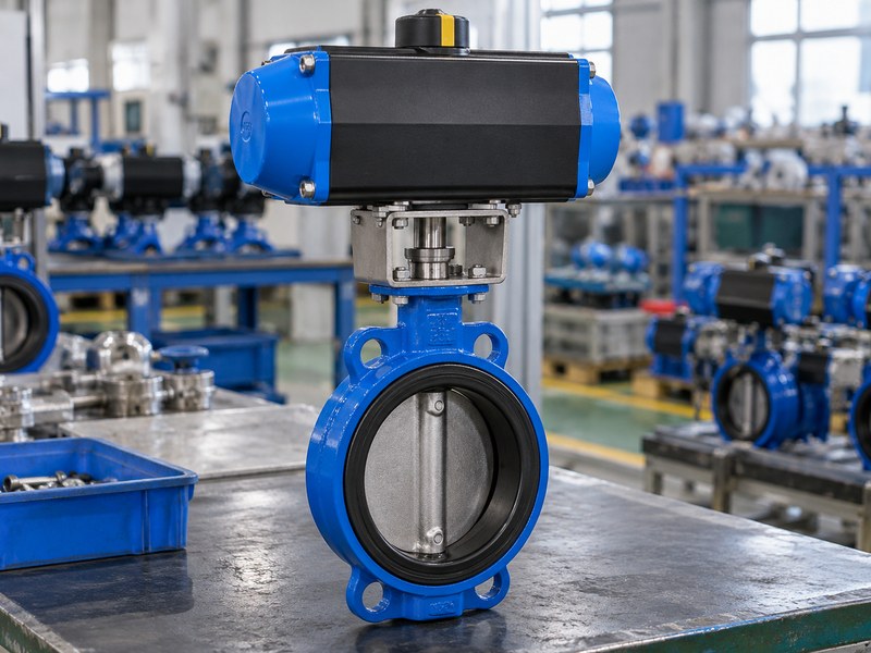
Suitable pneumatic butterfly valve manufacturers take responsibility for the valve, actuator, mounting parts, accessories, and their combined performance. A quotation listing these components separately leaves you to resolve torque, travel, wiring, and failure behaviour. Ask who approves the assembly and who provides one controlled drawing and parts list for the package.
Define the complete scope of supply
- State the actual fluid, operating conditions, closing differential, and valve connection.
- Specify air conditions, command signal, feedback, and required operating sequence.
- Identify responsibility for mounting, tubing, wiring, settings, and final testing.
RUITO selects manual, electric, or pneumatic operation against the configured butterfly valve's duty. The actuator does not expand the body, seat, lining, or process-fluid limits. Your enquiry should identify whether the package performs occasional isolation, frequent cycling, or modulating duty so engineering can review the proposed assembly accordingly.
| Supply scope | Supplier deliverable | Buyer acceptance |
|---|---|---|
| Valve | Materials and service limits | Matches process duty |
| Actuation | Output and mounting selection | Matches required torque |
| Controls | Pneumatic and electrical details | Matches control system |
| Complete package | Assembly drawing and test record | Works as an identified unit |
Compare quotations using the same scope before calculating the cost of site assembly or missing accessories.
2. What is the difference between air supply and process fluid?
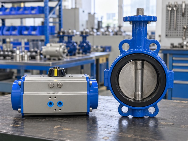
Air supply powers the actuator, while process fluid passes through the valve; pneumatic butterfly valve manufacturers must specify these as separate inputs. A water valve can have a compressed-air actuator. That arrangement does not make it a valve for compressed air, nitrogen, natural gas, or another process gas.
Prepare two sets of operating data
- For the valve, state fluid composition, concentration, pressure, temperature, and flow.
- State the actuator’s minimum and maximum air pressure, temperature, and air quality requirements.
- For accessories, state ambient exposure, electrical supply, and any required area classification.
RUITO's defined clean air or nitrogen butterfly configuration is a separate product duty, with its own materials and gas leakage checks. Pneumatic operation does not confer natural gas suitability on that valve. Natural gas service requires a dedicated product and the applicable engineering and market review; it cannot be inferred from the word “pneumatic.”
| Input | Belongs to | Required supplier response |
|---|---|---|
| Water or chemical composition | Valve wetted path | Material compatibility |
| Minimum instrument air | Actuator supply | Available output |
| Ambient temperature | Entire external assembly | Component suitability |
| Electrical command | Solenoid or positioner | Signal and wiring match |
Keep process pressure and actuator air pressure in separate fields on the approved data sheet.
3. How do pneumatic butterfly valve manufacturers size actuators?
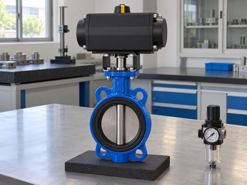
Size the actuator by comparing its output at minimum available air pressure with the valve's required torque throughout travel; pneumatic butterfly valve manufacturers should document that calculation. A nominal header pressure can overstate pressure available at the actuator while several devices operate. Use the minimum pressure expected at the actuator connection under the specified demand.
Compare torque at matching travel positions
- Obtain valve starting, running, and seating torque for the actual closing differential.
- Review actuator output throughout both required strokes, including spring action where fitted.
- Agree the sizing margin and check maximum output against shaft and mounting limits.
Include temperature, seat condition, operating frequency, and expected service effects in the engineering basis. A larger actuator can exceed allowable shaft or coupling loads if supply pressure rises. Record regulator settings and the accepted maximum supply pressure alongside the minimum pressure used for selection.
| Torque condition | Required comparison | Evidence to request |
|---|---|---|
| Start of movement | Available versus break torque | Valve and actuator data |
| Mid travel | Output versus running requirement | Travel-based comparison |
| Seating | End output versus closing torque | Differential-pressure basis |
| Maximum supply | Delivered versus allowable load | Shaft and mounting check |
An unloaded cycle test confirms movement but needs a documented load basis before it supports your process-duty acceptance.
4. Should you choose spring return or double acting?
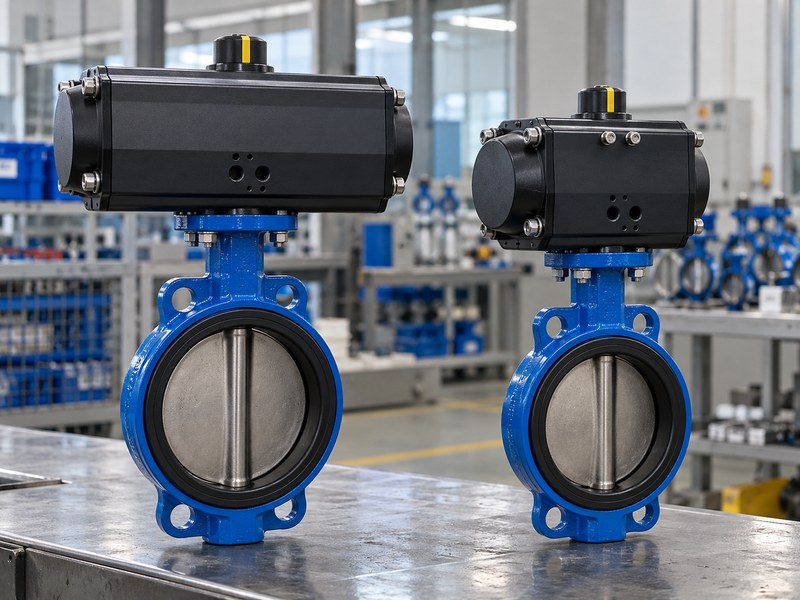
Choose spring return when an engineered spring-driven stroke meets the required failure action, or double acting when air-driven travel in both directions suits the control design; pneumatic butterfly valve manufacturers should compare both against your duty. Neither choice determines the complete failure behaviour without the valve orientation and pneumatic circuit.
Compare both strokes before deciding
- For spring return, check air-stroke and spring-stroke output across travel.
- For double acting, check output in both directions at minimum air supply.
- Confirm mounting orientation, travel stops, circuit arrangement, and manual override requirements.
Double acting does not guarantee that a valve holds its last position after air loss. Leakage, trapped air, accessory arrangement, process torque, and other loads can affect movement. If the process requires a defined position after supply loss, have the supplier propose and verify the complete arrangement that provides it.
| Selection issue | Spring return | Double acting |
|---|---|---|
| Driving energy | Air and stored spring energy | Air for both directions |
| Torque review | Air and spring curves | Both air-driven strokes |
| Failure action | Depends on assembly and circuit | Requires explicit design |
| Acceptance | Verify configured return stroke | Verify agreed supply-loss response |
Ask for the pneumatic schematic with the quotation so the operating concept can be reviewed before hardware selection.
5. Which failure state does your system need?
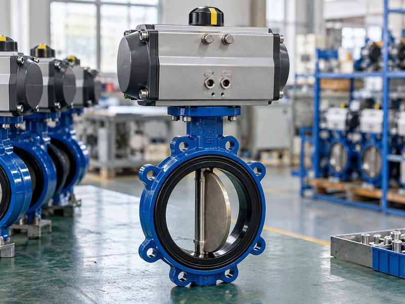
Your process risk review should define the required state for each credible failure, and pneumatic butterfly valve manufacturers should implement that instruction in the assembly. A cooling branch may need a different response from a chemical feed line. “Fail safe” leaves the direction, trigger, timing, and confirmation method unspecified.
Write a failure response matrix
- Define separate responses to electrical power loss and instrument-air loss.
- Identify required behaviour when the control signal disappears.
- State the expected action on restoration, including any manual reset.
Check that mechanical orientation, solenoid function, tubing, and control logic agree with the matrix. Position switches should report the agreed physical positions, and your controls team should decide what happens when command and feedback disagree. Have the responsible process engineer approve the failure requirements before the supplier sets up the actuator.
| Event | Buyer must define | Factory verification |
|---|---|---|
| Electrical power loss | Required position and timing | De-energized circuit response |
| Air supply loss | Required position or other action | Agreed loss-of-air test |
| Command loss | Control response | Signal-loss simulation |
| Supply restoration | Restart or reset sequence | Agreed recovery check |
Record the test configuration because a changed solenoid or tubing arrangement can change the observed response.
6. How do you check the bracket and coupling?
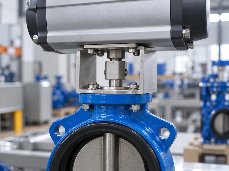
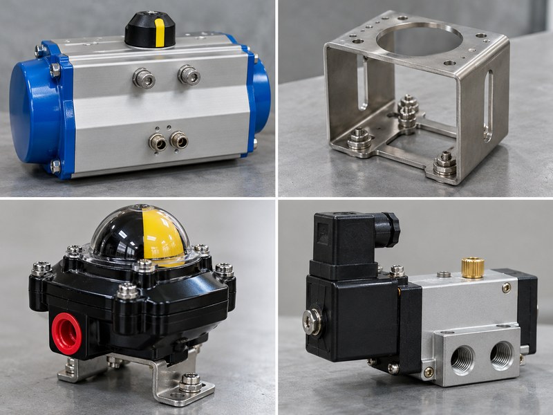
Check alignment, strength, engagement, travel, and assembly access with pneumatic butterfly valve manufacturers before approving mounting parts. A matching mounting flange designation leaves the shaft connection and bracket geometry to be confirmed. Misalignment can load the valve shaft, distort the coupling, or create uneven movement during cycling.
Review the mechanical connection as an assembly
- Confirm valve and actuator mounting patterns, shaft forms, and coupling engagement.
- Check alignment, fastener requirements, and allowable transmitted torque.
- Review the operating envelope, accessory clearance, and removal route.
Where ISO 5211 interfaces apply, identify the actual interface details on the drawing instead of relying on that standard name alone. Show the valve position, actuator orientation, coupling, bracket, and travel-stop settings together. If an OEM requires repeat assembly without adjustment, freeze these parts and dimensions in the controlled package.
| Mounting feature | Review evidence | Functional risk |
|---|---|---|
| Shaft connection | Dimensions and engagement | Slip or excessive play |
| Bracket | Drawing and load review | Deflection or misalignment |
| Fasteners | Grade and assembly procedure | Loosening or overstress |
| Assembly envelope | Approved assembly model | Installation obstruction |
After assembly, verify full travel and correct indication before setting accessories or applying final identification labels.
7. Which accessories must be specified together?
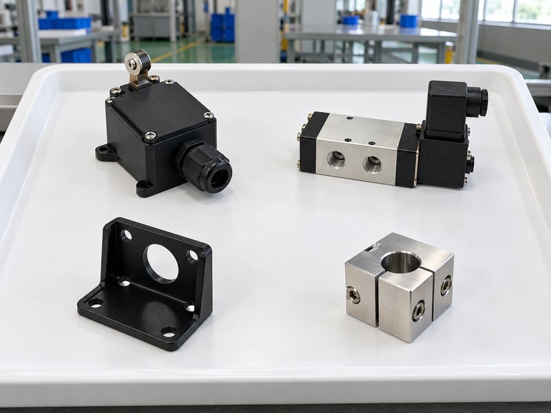
Specify solenoids, position indication, air preparation, tubing, speed controls, and any positioner as one control package with pneumatic butterfly valve manufacturers. An accessory substitution can alter signal compatibility, available airflow, travel time, or failure action. List the required function and the accepted component configuration before evaluating brands or prices.
Match accessories to the control system
- Confirm voltage, electrical load, connection, and switching arrangement.
- Identify feedback type, terminal assignments, and required open or closed indication.
- Define environmental protection and any project-specific hazardous-area documentation.
For modulating duty, specify the input and feedback signals, required response, and control-system interface. Ask whether the proposed valve and actuator arrangement supports the expected operating frequency and travel pattern. A limit switch indicates position; it cannot demonstrate that the seat meets its leakage requirement.
| Accessory | Input to specify | Assembly check |
|---|---|---|
| Solenoid | Voltage and pneumatic function | Command and failure response |
| Limit switches | Contact or signal type | Actual position and terminals |
| Positioner | Input and feedback | Travel and response |
| Air preparation | Supply and quality needs | Setting and pressure drop |
| Tubing and exhaust | Routing and environment | Flow and protection |
Keep the wiring and pneumatic diagrams at the same revision as the supplied accessory list.
8. How can you control the stroke time?
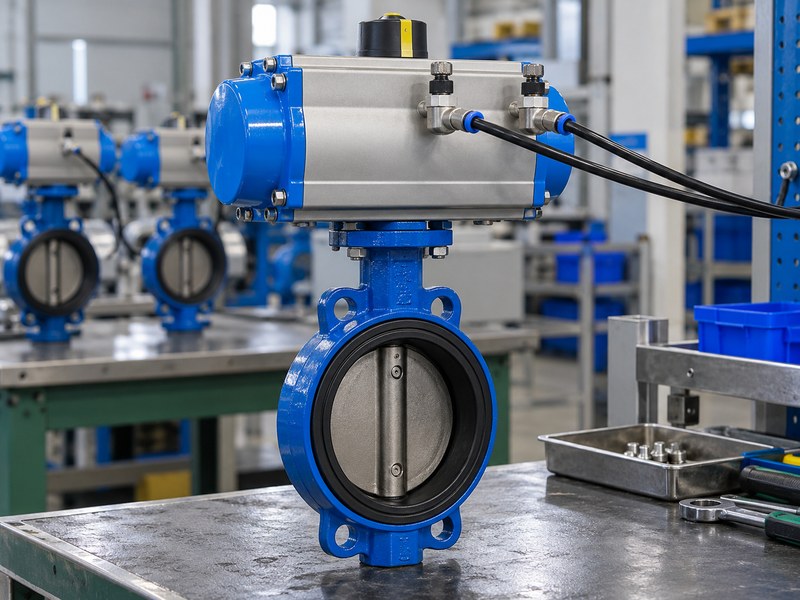
You can control stroke time through an engineered pneumatic circuit and agreed settings, and pneumatic butterfly valve manufacturers should verify both normal and failure strokes. Opening and closing times affect equipment sequencing and liquid pressure transients. The fastest available movement may exceed the acceptable response of your pipe system.
Define time against operating conditions
- State separate opening, closing, and failure-action time requirements.
- Identify the air pressure and load conditions for the timing test.
- Agree which adjustments may be changed during site commissioning.
Tubing, accessory flow capacity, exhaust restrictions, and actuator volume influence travel time. For a spring return assembly, the circuit also affects how air exhausts during the spring-driven stroke. Have the system designer review the closing profile where water hammer is a concern; a factory stopwatch reading cannot validate the complete pipeline transient response.
| Timing requirement | Test condition to record | Site follow-up |
|---|---|---|
| Normal opening | Air supply and command | Equipment sequence |
| Normal closing | Circuit setting and load basis | Pressure transient review |
| Failure stroke | Exact simulated failure | Required process response |
| Repeated cycles | Agreed test sequence | Available air during demand |
Record accepted speed settings and identify who may alter them after the factory test.
9. How do pneumatic butterfly valve manufacturers test assemblies?
A complete assembly test should prove the agreed mechanical travel, control response, indication, and failure behaviour of the identified package; pneumatic butterfly valve manufacturers should also provide the separate valve pressure records. Testing an actuator and valve individually leaves mounting, wiring, tubing, and settings unverified after assembly.
Test the unit that will be shipped
- Match valve, actuator, mounting parts, and accessory identities to the approved list.
- Check cycling, stops, command response, feedback, and agreed failure events.
- Record supply conditions, settings, observations, and any repaired or repeated tests.
Separate a functional cycle at minimum air from evidence of torque capacity at the required process differential. Agree the calculation, representative testing, or loaded test method that supports that requirement. Seat leakage acceptance also needs its approved medium, pressure, direction, duration, and criterion; a closed position signal does not establish tightness.
| Acceptance item | Required evidence | Unresolved by that evidence |
|---|---|---|
| Valve shell and seat | Pressure test record | Automation function |
| Complete travel | Assembly functional record | Process-load torque alone |
| Torque selection | Approved load/output comparison | Wiring correctness |
| Command and feedback | Interface test | Seat leakage |
| Failure response | Defined event simulation | Unspecified failure scenarios |
Close deviations before packing and retain the settings as the baseline for site commissioning.
10. What should your automation enquiry include?
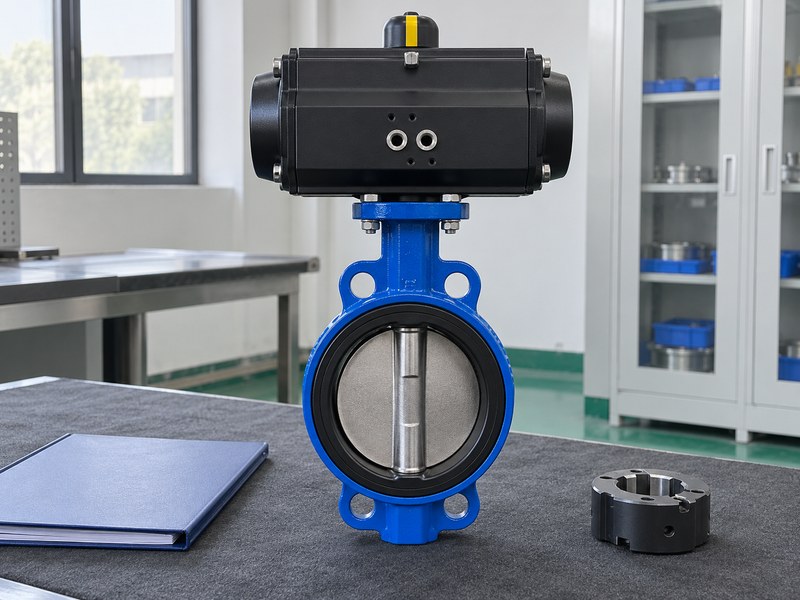
Your enquiry should give pneumatic butterfly valve manufacturers one consistent set of process, air, control, installation, and acceptance requirements. Attach the valve schedule, mating flange information, and required delivery sequence. Ask suppliers to identify exceptions explicitly so your engineers can resolve them before the sample enters equipment testing; contact us to request a configuration review.
- Include minimum and maximum air supply at the actuator connection.
- Provide the failure response matrix and required stroke times.
- Request controlled drawings, torque selection, diagrams, and an assembly test plan.
Questions to settle before sample approval
Q1. Can a pneumatic water valve handle natural gas?
Pneumatic operation does not establish natural gas suitability. The valve needs a dedicated process-service configuration and the applicable engineering and destination requirements satisfied.
Q2. What is the best air pressure for actuator selection?
Use the minimum available pressure at the actuator under specified operating demand for output selection. Check maximum supply separately against component and shaft limits.
Q3. Will a double acting actuator stay put after air loss?
You cannot assume that response. The circuit, trapped air, leakage, and process torque affect movement; specify and verify the required behaviour.
Q4. Can I approve an assembly from an unloaded cycle?
You can confirm travel and control response under those conditions. Required process-load torque and seat leakage still need their agreed supporting evidence.
Q5. How do I keep replacement assemblies interchangeable?
Freeze the valve, actuator, bracket, coupling, accessories, wiring, and settings under controlled revisions. Review changes before they enter a repeat order.
Send RUITO your process data, minimum air supply, control signals, failure matrix, and installation drawing. Request an engineering review of torque, mounting, accessories, and the complete assembly acceptance plan before releasing your sample order.