
You can avoid costly offset valve mistakes by checking a resilient seat offset butterfly valve against its shaft geometry, seal construction, directional closing limits and complete operating duty. A specification that says only “double offset, PN16” leaves several decisions unresolved. The installation may need reverse isolation, a particular flange length or a closing sequence that the quoted configuration has never been assessed against. Obtain those answers in the drawing, materials list and test plan before selecting the operator or approving the order.
1. What is a resilient seat offset butterfly valve?
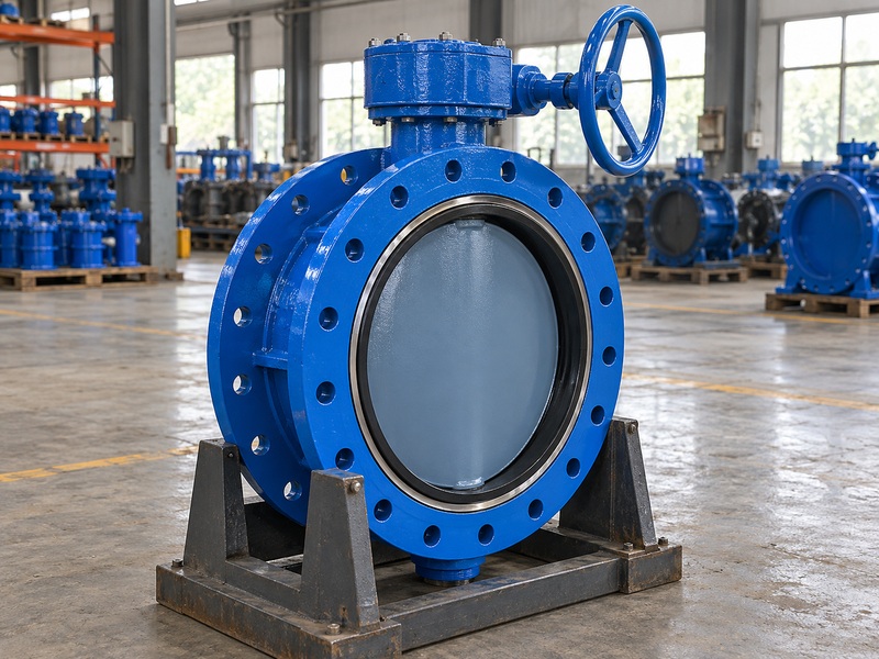
A resilient seat offset butterfly valve combines an offset shaft arrangement with a sealing element that deforms elastically to make the shutoff seal. The term describes both geometry and sealing behavior. It does not establish the fluid, temperature, pressure rating or seat material without the manufacturer’s exact configuration data.
Which features should the supplier identify?
In a double offset design, one rotating shaft has two geometric offsets. One offset locates its axis away from the sealing plane; the other displaces it from the pipe bore centerline. These are two positional relationships of one shaft, rather than two separate shafts driving the disc.
The controlled section drawing should identify the shaft axis, bore centerline and sealing plane. It should also show where the resilient sealing ring sits and how it is retained. Depending on the design, that ring may belong to the disc assembly or another defined sealing arrangement.
- Request a sectional drawing for the offered valve.
- Identify the resilient ring and its mating surface.
- Match drawing revisions to the quoted assembly.
| Description | What it establishes |
|---|---|
| Double offset | Two defined geometric offsets of one shaft |
| Resilient seal | Elastic deformation at the sealing interface |
| Double flanged | The pipe connection arrangement |
Keep these three descriptions separate when reviewing a supplier’s response.
2. How does offset geometry affect the seal?
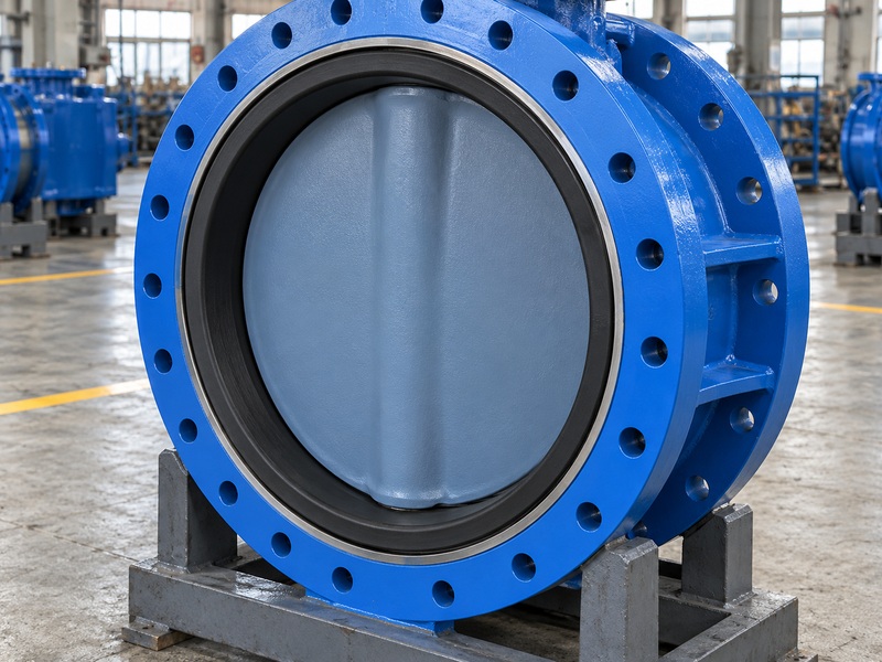
Offset geometry changes how a resilient seat offset butterfly valve approaches and leaves its sealing surface during rotation. It can reduce the portion of travel in which the seal rubs against its mating surface, depending on the actual geometry. The drawing and validated operation determine that contact behavior.
How should you compare it with a concentric valve?
A concentric arrangement places the shaft along the central disc and bore relationship defined by its design. Its resilient seat contact and interference must suit the specified duty. An offset arrangement changes those relationships, but the word “offset” alone cannot quantify friction, service life or actuator torque.
For a smaller clean water installation, compare the proposed offset assembly with an appropriately selected wafer butterfly valve using the same operating inputs. The useful comparison includes torque, acceptable leakage, mechanical fit and maintenance access. Avoid choosing geometry from an unsupported claim of longer life.
- Compare starting, running and final seating torque.
- Ask how the seal is adjusted or replaced.
- Review evidence for the intended operating frequency.
| Review point | Concentric and offset comparison |
|---|---|
| Seal contact | Confirm actual contact through the stroke |
| Operating torque | Compare calculations under the same duty |
| Maintenance | Check ring retention and access requirements |
Use a documented benefit tied to the application when accepting a design change.
3. Does an offset valve always have a metal seat?
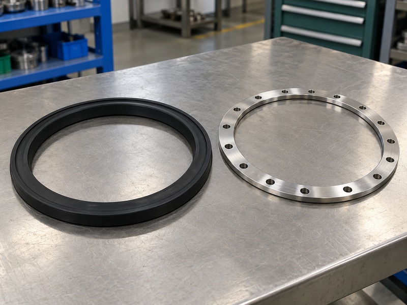
No, a resilient seat offset butterfly valve can use an elastomer sealing ring, so shaft geometry does not identify a metal seated valve. The mating seat ring may be metal while the element that produces the resilient seal is EPDM. Name each component when discussing its material or performance.
What should the materials list explain?
RUITO’s supplied large water valve example uses a ductile iron body and disc, stainless steel shaft and seat ring, and a replaceable EPDM sealing ring. That combination is a specific water configuration. A stainless steel seat ring does not turn its EPDM shutoff system into a metal to metal sealing design.
Ask which surfaces contact the fluid during normal operation and which become exposed if a primary seal is damaged. Include the sealing ring compound, retainers, shaft seals and coating. A body material description cannot establish the corrosion or temperature limits of the completed valve.
- Identify the actual deformable sealing element.
- Check its compound against the complete fluid.
- Confirm spare ring identity and replacement procedure.
| Component description | Question to resolve |
|---|---|
| Seat ring | Mating surface material and geometry? |
| Resilient ring | Exact compound and retention method? |
| Shaft seals | Materials and external leakage requirements? |
A labeled materials list prevents ambiguity between the seating surface and the resilient seal.
4. Which RUITO operating boundaries apply?
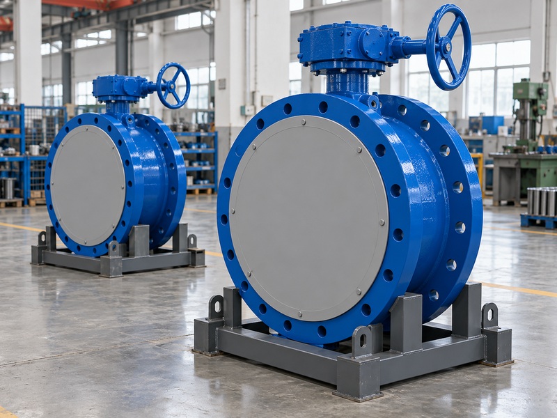
RUITO’s large resilient seat offset butterfly valve offering is a double flanged, double offset water focused configuration covering DN350–3000 and PN10/16. Forward and reverse allowable closing differentials are stated separately. The diameter and nominal pressure range does not create one common operating envelope for every supplied assembly.
Which applications require a separate review?
Clean water, approved circulation liquids, drinking water and treated water need their own materials and operating limits. RUITO’s circulation liquid configurations cover clean water or inhibited glycol solutions with 0–40% glycol by volume, 5–60°C and working pressure no greater than 10 barg, subject to the exact configuration. Additives, viscosity and pressure transients still require assessment.
The large water configuration does not inherit steam, hydrocarbon, high temperature or fire test qualification. Chemical service may instead require a dedicated PTFE lined butterfly valve with separate size, pressure, lining and shaft seal limits. A different material name on a quotation cannot establish the needed validation.
- Apply the exact configuration’s pressure-temperature limits.
- Check drinking water documentation by covered model.
- Keep special fluid approvals independent.
| Proposed service | Required basis |
|---|---|
| Water | Exact water configuration and operating envelope |
| Drinking water | Covered materials, model and destination documents |
| Other process fluid | Separate compatibility and qualification review |
Select the complete valve arrangement before assigning an application to it.
5. Why can forward and reverse closing limits differ?
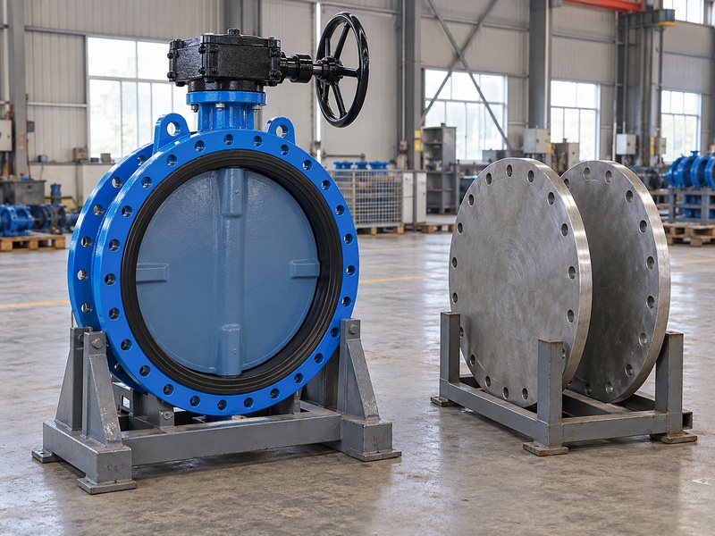
Forward and reverse limits can differ because pressure loads the disc, shaft and seal arrangement differently in a resilient seat offset butterfly valve. Ask for the permitted closing differential in each direction, together with the manufacturer’s direction reference. Nominal body pressure and allowable closure differential describe different conditions.
What does the supplied DN2400 project show?
RUITO supplied two DN2400 PN16 double flanged double offset valves for a clean water transmission project. Their project conditions included 15–35°C water, working pressure around 8 bar, maximum forward closing differential of 10 bar and reverse closing differential of 6 bar. Those limits belong to that project configuration.
The recorded acceptance inputs were a 24 bar shell test, 17.6 bar forward closure test and 6.6 bar reverse closure test under the agreed procedure. Neither the forward inspection pressure nor the PN16 designation increased the permitted reverse operating differential above 6 bar. Do not transfer these project figures to another size or valve construction.
- Define forward direction on drawings and site documents.
- Check isolation with either side depressurized.
- Include pump stops and abnormal pressure states.
| Pressure term | What to verify |
|---|---|
| Body rating | Allowable pressure at operating temperature |
| Closing differential | Maximum permitted difference by direction |
| Test input | Approved inspection condition and acceptance rule |
Use the direction specific operating limits when preparing the isolation plan.
6. Which installation details cause expensive mismatches?
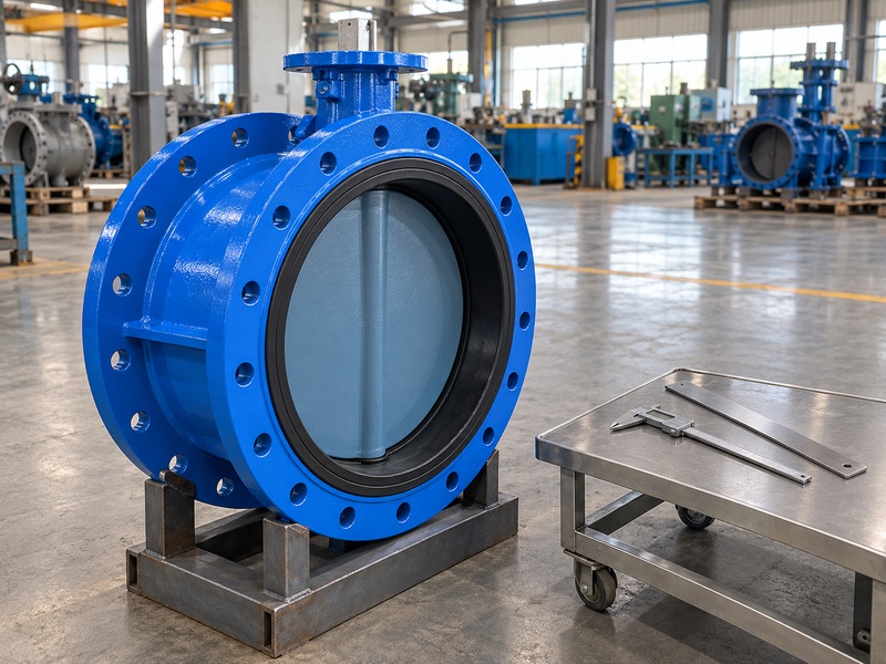
Face length, flange geometry, disc sweep and lifting space can make a resilient seat offset butterfly valve incompatible with an otherwise matching pipeline size. Obtain the approved general arrangement drawing before freezing pipe spools or supports. A nominal diameter cannot describe the complete installation envelope.
What belongs in the mechanical fit review?
Check the flange standard, drilling, sealing face and mating pipe bore, then review the disc envelope at every required position. Include adjacent reducers, linings and equipment nozzles. Confirm the orientation of the shaft and operator against the manufacturer’s instructions and the space available for servicing them.
A double flanged large valve also needs a defined support and lifting arrangement. Its installation cannot be copied from a lug butterfly valve drawing. Obtain the actual mass, center of gravity, lifting points and permitted handling orientation for the supplied unit; use those values for the site lifting and transport plans.
- Check removal clearance for the operator and seal.
- Confirm pipe loads and support responsibilities.
- Protect flange faces and sealing surfaces in transit.
| Interface | Evidence to approve |
|---|---|
| Pipeline | Flange details, face length and bore clearance |
| Structure | Supports and allowable imposed loads |
| Handling | Unit mass, lifting points and transport envelope |
Complete the dimensional review while changes to the surrounding pipework are still manageable.
7. How should the operator and closure time be selected?
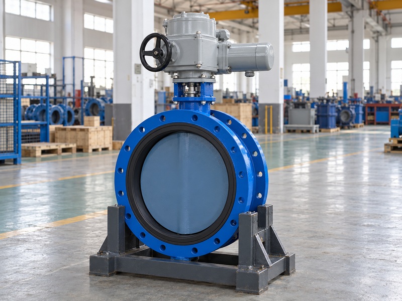
Select the operator for a resilient seat offset butterfly valve from the valve torque requirements, available power and approved closing sequence. Include starting, running and final seating conditions, plus both required pressure directions. The operator must provide the necessary movement without exceeding the valve’s permitted shaft or drive loads.
Why must the pipeline review include closing time?
The selected closing movement affects changes in flow and pressure across the pipeline. A rapid final movement can interact with pump behavior and the water column. The project engineer should review surge conditions and establish an acceptable closure sequence rather than choosing speed solely from an actuator catalog.
Provide the lowest available electrical or pneumatic supply, operating frequency, local and remote control requirements and needed position feedback. Confirm limit and torque settings during commissioning. An offset geometry description cannot establish the actuator output or prove that an automated assembly is suitable for repeated throttling.
- Check minimum supply and required failure behavior.
- Confirm mechanical stops and control settings.
- Validate the agreed stroke during functional testing.
| Operator input | Decision supported |
|---|---|
| Valve torque | Required output across the stroke |
| Available power | Performance at the lowest supply condition |
| Pipeline response | Permitted closure timing and sequence |
Keep the approved operator calculation and control settings with the valve records.
8. Which test records should you accept?
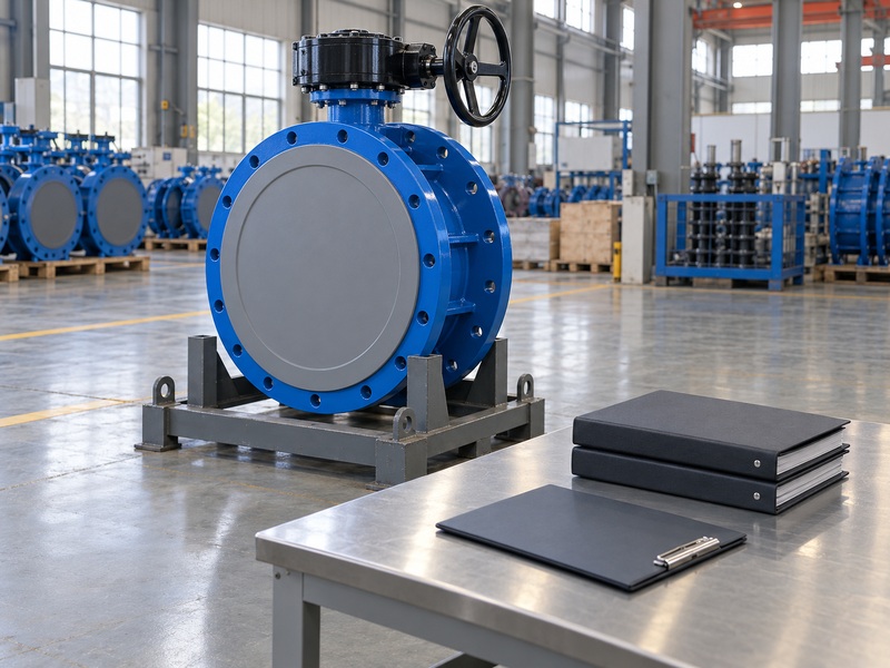
Accept records that identify the resilient seat offset butterfly valve, test direction, pressure, duration, medium and acceptance criterion. Link them to the actual unit and approved inspection plan. A report for a different diameter or construction may support a defined qualification argument, but it cannot replace required unit acceptance records.
How should the pressure procedure be specified?
The primary standard ISO 5208 covers pressure testing of industrial metallic valves. RUITO uses EN 12266-1 or contract selected ISO 5208 as the main pressure route. The selected procedure must respect the stated seat differential rating, including any lower reverse limit.
Rate A means no visible leakage under the chosen standard’s specified test conditions. It does not promise unchanged sealing under every temperature, fluid or future operating condition. Separately review material traceability, critical dimensions, coating checks, seal installation and functional operation as required by the inspection plan.
- Verify instrument identification and calibration status.
- Confirm agreed witness and hold points were addressed.
- Retain original results with the unit identification.
| Record | Minimum useful identification |
|---|---|
| Pressure test | Unit, direction, input and acceptance result |
| Materials | Approved grades, seal compound and traceability |
| Function | Operator assembly, stroke and settings |
Resolve discrepancies before factory release, while the unit and inspection team remain available.
9. What should you send for a defensible selection?
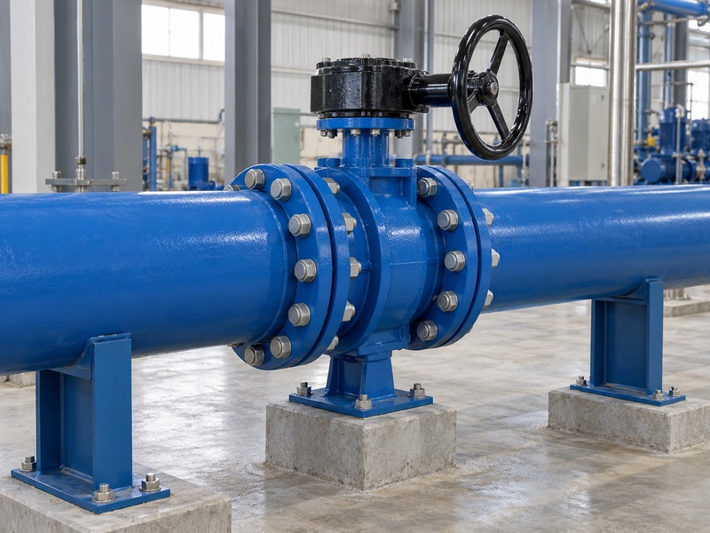
Send a complete duty sheet and installation package when requesting a resilient seat offset butterfly valve selection. Include ordinary operation, shutdown isolation, reverse pressure and foreseeable transient conditions. State which values are confirmed and which still need project engineering approval so the supplier can identify unresolved assumptions.
Which documents should close the review?
Require a configuration specific quotation, general arrangement drawing, materials list, pressure-temperature limits, directional differential statement and operator calculation. Add the inspection plan, maintenance instructions and spare sealing ring identification. If the fluid or closure sequence changes later, reopen the affected parts of the review before using the original approval.
| Buyer input | Supplier response to request |
|---|---|
| Complete fluid and temperature duty | Materials and operating envelope |
| Directional pressure scenarios | Closing limits and torque assessment |
| Pipeline and control information | Installation drawing and operator selection |
Agree document revisions and responsible reviewers before placing the order. For large pieces, also confirm the manufacturing, lifting, test equipment and dispatch plan against the required project dates.
To review a proposed water valve configuration, contact us with your valve schedule, directional pressure cases, pipe drawings and operator requirements. Request a written response to each exception before releasing the approved drawings for manufacture.
10. What do engineers ask about offset water valves?
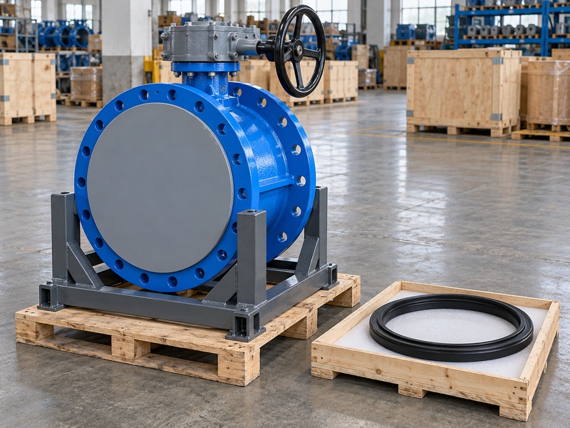
Engineers ask whether a resilient seat offset butterfly valve has the correct sealing materials, directional pressure limits, closing sequence and acceptance evidence for their water system. The accepted configuration documents establish the supplied limits.
Q1. Can I use an offset valve with an EPDM seal?
Yes, if the exact valve configuration is approved for the duty. Offset geometry and an elastomer seal can coexist in the same assembly.
Q2. Does double offset mean two shafts?
No. It describes two geometric offsets associated with one rotating shaft. Ask for a labeled section drawing if the arrangement is unclear.
Q3. Can I assume a PN16 valve closes against 16 bar both ways?
No. Verify the allowed closing differential in each direction and at the operating temperature. Those limits may differ from the body rating.
Q4. What’s the best closing time for a large water valve?
Use the time established by the pipeline and surge review. The appropriate sequence depends on the pumps, pipe system and operating scenarios.
Q5. How do I know whether a valve is fire safe?
Check the applicable qualification report and its covered configuration. A water duty offset valve does not acquire fire test qualification from its geometry or metal components.