
Check a resilient seated concentric butterfly valve by comparing its section drawing, shaft arrangement, seat support and installed disc clearance. An external photograph cannot establish all four. If a valve turns freely before installation but binds between the flanges, examine the interface and assembly conditions before changing the drive or rejecting the concentric design.
1. What defines a resilient seated concentric butterfly valve?
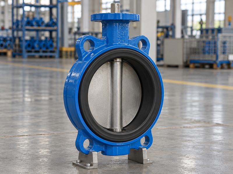
A resilient seated concentric butterfly valve has a centered shaft arrangement relative to its circular bore and disc geometry. The elastomer seat supplies the deformable sealing surface. The drawing must establish the actual relationship between the shaft axis, disc and seat; the product label does not supply a manufacturing tolerance or an inspection result.
Which features should you identify?
Find the bore centerline, shaft axis, disc sealing edge and seat contact zone on the approved section. Keep these features separate from the mounting face and outside casting profile. A symmetrical body casting or a centered handwheel can suggest a construction, but neither substitutes for the internal drawing.
- Identify the internal centerlines and contact surfaces.
- Locate the shaft support and retention features.
- Record the applicable drawing revision.
Why should you separate geometry and seat material?
Concentric describes an arrangement; resilient describes a sealing approach. An offset valve may also have an elastomer seal. If a quotation combines those terms loosely, request the section and parts list so you can determine what construction the supplier is offering.
| Feature | What it describes |
|---|---|
| Concentric arrangement | Shaft, bore and disc relationship |
| Resilient seat | Deformable sealing element |
| Drawing tolerance | Permitted manufacturing variation |
2. Which drawings can confirm the construction?
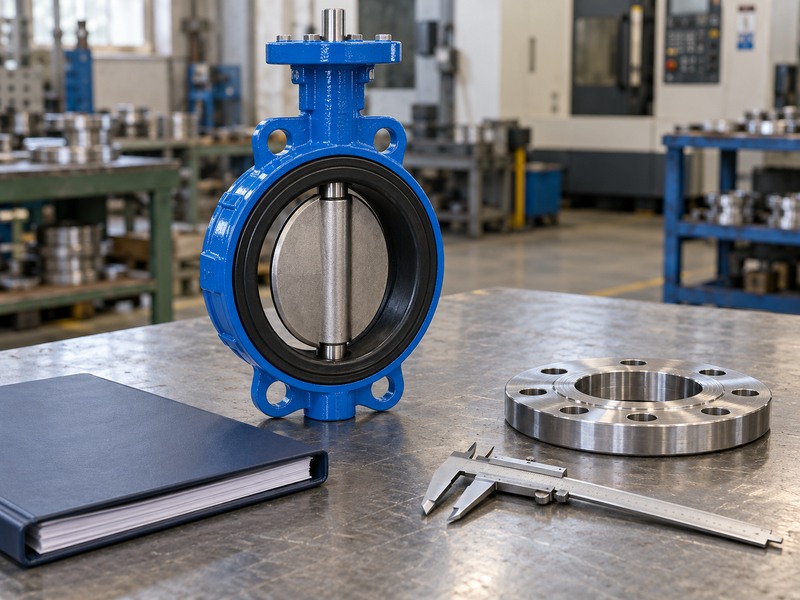
Use a section drawing to confirm the internal geometry of a resilient seated concentric butterfly valve, then use its general arrangement drawing to check the installation envelope. The two documents answer different questions. A face-to-face dimension and flange pattern can establish fit without revealing the seat retention or shaft sealing arrangement.
What belongs on the installation review?
Compare nominal size, connection, face-to-face length, disc sweep and operator space with the pipe layout. For a replacement, include the minimum pipe bore and nearby restrictions. RUITO’s wafer butterfly valve construction provides a starting point, but the approved drawing for your configuration governs the interface.
- Compare the actual connection standard and drilling.
- Review the disc envelope beyond the body faces.
- Check access for the selected operator.
How do you handle a drawing discrepancy?
List the difference and obtain a revised drawing or an approved deviation before manufacture or installation. Do not resolve a missing dimension by scaling a photograph. If the supplier changes a sealing or supporting part, ask whether the change affects the assembly, inspection plan and spare part revision.
| Document | Question it answers |
|---|---|
| Section drawing | How do the internal parts engage? |
| General arrangement | Will the assembly fit the installation? |
| Parts list | Which materials and revisions are supplied? |
3. How do you check the shaft and drive connection?
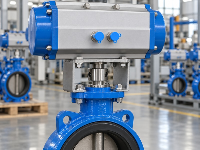
Check that the drive connection on a resilient seated concentric butterfly valve transmits rotation in the specified orientation and remains within its permitted load. The bracket, coupling and mounting interface must correspond to the valve and operator. A matching bolt pattern alone does not establish a compatible assembled drive.
Which connection details need confirmation?
Compare the shaft end shape, coupling engagement, mounting orientation and retention method against the assembly drawing. Where a key, square or another profile transfers torque, use the specified matching parts. Enlarging a coupling or forcing a mismatched component onto the shaft can change how the assembly carries load.
- Confirm the shaft and coupling profiles.
- Check engagement and retention against the drawing.
- Align the physical valve position with the operator indication.
Can you increase torque to overcome a fit problem?
Do not use a larger drive to compensate for an unexplained obstruction or misalignment. Establish the required breakaway, running and seating torque for the approved duty, then compare it with the operator output and shaft limits. The reason for abnormal resistance needs investigation before the valve returns to service.
| Assembly field | Evidence to compare |
|---|---|
| Mechanical interface | Valve and operator drawings |
| Coupling engagement | Approved assembly details |
| Permitted torque | Valve requirements and shaft limits |
4. What can uneven seat contact tell you?
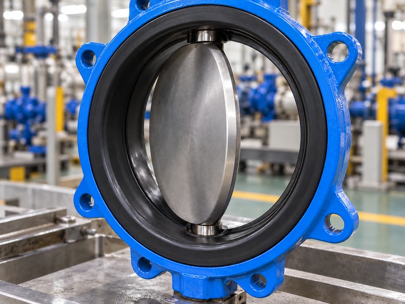
Uneven contact in a resilient seated concentric butterfly valve can indicate an installation, assembly or damage problem, but the visible pattern alone does not identify the cause. Review the seat condition, disc edge and supporting geometry together. Particles, swelling, a rolled liner or an unsuitable interface can produce different symptoms that require different corrections.
What should an inspection record include?
After safe isolation, depressurization and any necessary decontamination, record where damage appears relative to the shaft and flange faces. Photograph cuts, deformation and trapped debris without disturbing the evidence unnecessarily. Keep the fluid composition, operating temperature and closure differential with those observations.
- Note the location and form of the damage.
- Preserve the unit and material identification.
- Review installation and operating history together.
Should you alter the sealing edge to improve contact?
Follow the manufacturer’s repair procedure. Unapproved grinding, seat trimming or changes to stop settings can alter sealing geometry and the operating load. If a part needs replacement, use the approved material and revision and agree on the inspection required after repair.
| Observation | Review alongside it |
|---|---|
| Local cut | Debris and installation history |
| General swelling | Actual fluid and cleaning chemicals |
| Distorted seat lip | Flange arrangement and assembly method |
5. How can flange installation disturb the liner?
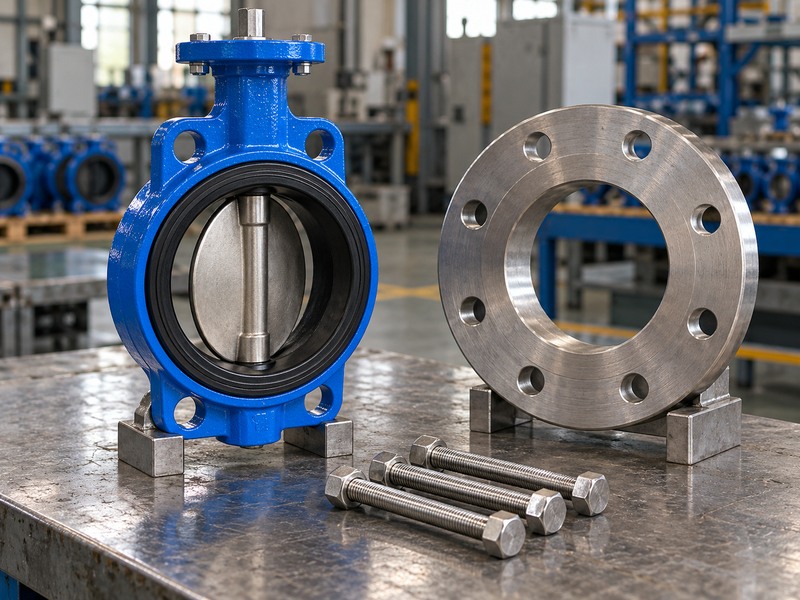
Flange alignment and compression can affect the liner of a resilient seated concentric butterfly valve. Check that the faces and bore suit the approved seat construction. If the design uses the liner’s molded faces as the flange seal, adding another gasket may change how the elastomer is compressed.
Which instructions should installers follow?
Use the valve-specific installation procedure for disc position, fasteners, gasket requirements and tightening sequence. Support and align the pipe independently. Drawing the pipe into alignment with the valve bolts can load the assembly in a way that the free-standing factory function check did not represent.
- Clean and inspect the mating faces.
- Confirm the required fasteners and engagement.
- Apply the specified sequence and tightening requirements.
Does a lug connection change the review?
A lug butterfly valve needs its own thread engagement and loading checks. Verify any requirement to remove a downstream pipe while the valve remains in place. Threaded lugs do not establish a universal end service rating, and the permitted condition must correspond to the exact construction.
| Interface concern | Confirmation needed |
|---|---|
| Extra gasket | Permitted by the valve instructions? |
| Pipe misalignment | Corrected without forcing the valve? |
| Lug bolts | Correct length and engagement? |
6. How do you establish disc clearance?
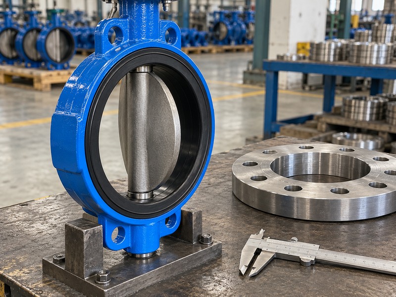
Establish disc clearance for a resilient seated concentric butterfly valve by comparing its complete sweep with the minimum adjacent bore. Nominal pipe size is insufficient. A thick lining, reducer or another nearby component can restrict the space available to the moving disc beyond the valve’s short body.
Which dimensions should you collect?
Obtain the actual flange bore, pipe inside diameter, lining thickness and distance to restrictions on both sides. Compare those inputs with the approved disc envelope. If the installation uses a different pipe specification from the original design, review the clearance again rather than assuming the nominal designation guarantees compatibility.
- Check the complete range of permitted travel.
- Review restrictions on both sides of the valve.
- Keep the measured interface dimensions with the drawing review.
Can you move the stops to hide interference?
Reducing travel to avoid a collision changes the valve’s operating condition. It may affect full opening, closure or position indication. Resolve the interface discrepancy with the supplier and project engineer instead of changing a stop setting without reviewing the resulting duty and acceptance requirements.
| Required input | Source |
|---|---|
| Disc sweep | Approved valve drawing |
| Minimum clear bore | Pipe and component dimensions |
| Restriction position | Installation layout or measured arrangement |
7. What determines the required operating torque?
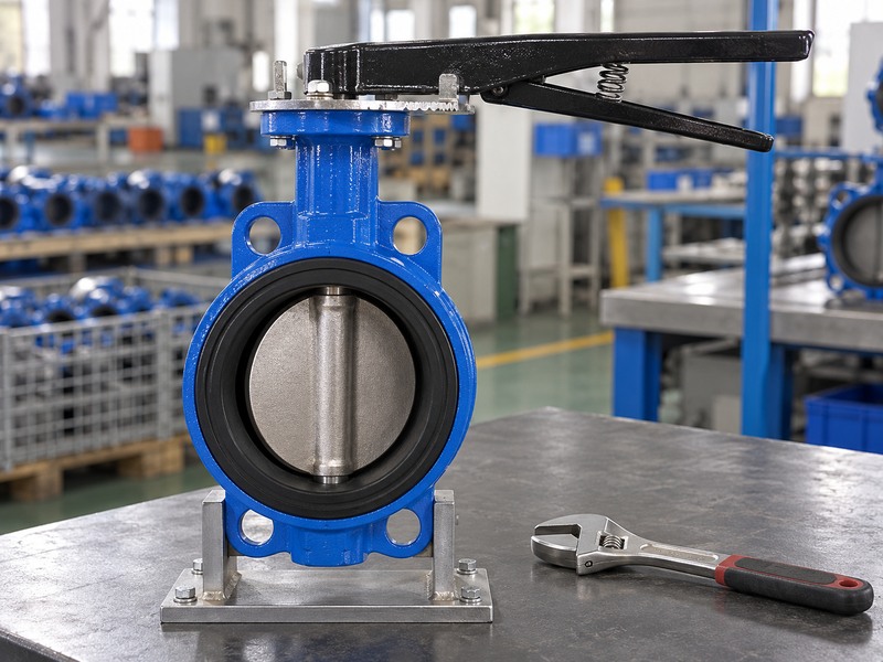
Operating torque for a resilient seated concentric butterfly valve depends on the selected construction and duty, including seat contact, differential pressure and service conditions. Obtain the applicable torque data for that configuration. A nominal diameter cannot establish a universal torque value for every elastomer, disc and operating condition.
How should you compare a powered operator?
Review breakaway, running and seating requirements across travel. For a pneumatic assembly, compare output at the minimum available air supply and check the required fail action. For an electric assembly, include supply, duty cycle and travel requirements alongside the torque and shaft limits.
- Match the output curve to the valve requirements.
- Review the complete bracket and coupling assembly.
- Confirm stops and indication during the function check.
What does a manual operating problem indicate?
Unusual effort warrants investigation of the disc, seat, interface and drive. Handle length changes the mechanical advantage, so subjective effort does not replace a defined torque assessment. Do not extend a lever or adjust an overload setting to force an unexplained obstruction.
| Torque assessment | Condition to record |
|---|---|
| Valve requirement | Exact configuration and differential |
| Pneumatic output | Minimum available supply |
| Electric output | Selected supply, duty and limits |
8. How should the function check be defined?
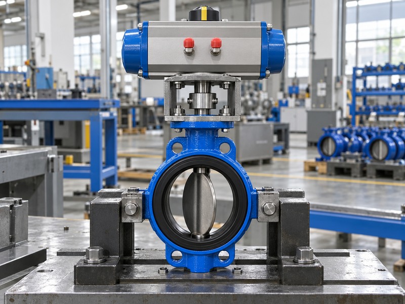
Define the function check for a resilient seated concentric butterfly valve using its approved procedure, operating medium and assembled drive. Record full travel, direction, indication and any abnormal behavior. If the manufacturer specifies lubrication or another preparation, use the approved materials rather than applying an unidentified workshop lubricant to the seat.
What should you verify after assembly?
Confirm that the physical disc position corresponds to the operator indication and required end positions. Inspect the mounting and retention features before operation. A function result for an unmounted operator does not demonstrate that the coupled valve assembly reaches its specified positions.
- Check the assembled valve and drive together.
- Use the required preparation and test conditions.
- Record abnormalities and the action taken.
How does this differ from pressure testing?
A travel check and a pressure test establish different facts. The pressure procedure has its own medium, pressure, duration, direction and leakage acceptance criterion. RUITO uses the applicable EN12266-1 or contract-selected ISO5208 route for its defined butterfly valve configurations; the agreed procedure must match the supplied model.
| Verification | Evidence produced |
|---|---|
| Assembly check | Mounting and retention conformity |
| Function check | Travel and indication correspondence |
| Pressure test | Result under defined inspection conditions |
9. Which records close the acceptance review?
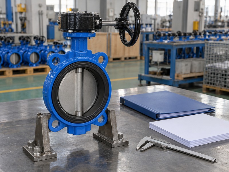
Close the acceptance review for a resilient seated concentric butterfly valve with records linking the unit to its drawings, materials, assembly and agreed tests. Record unresolved deviations rather than marking the package complete because one report is available. A pressure result cannot fill a missing interface or material approval.
What changes after a repair or substitution?
Identify the replacement part, compound and revision and determine which checks need repeating. A material or geometry change can affect the original review. Keep the approved change with the unit’s records so a future spare order does not recreate an earlier mismatch.
- Match the unit or batch to its inspection records.
- Retain the applicable drawing and parts list revisions.
- Close the required deviations before release.
What should you send for a technical assessment?
Provide the selected butterfly valve construction, unit identification, fluid, temperature, pressure and maximum closure differential. Include interface dimensions and photographs of the affected area. You can contact us with that package so RUITO can review the construction and proposed next steps.
| Record group | Link to preserve |
|---|---|
| Drawings and materials | Approved configuration and revision |
| Assembly and tests | Unit or batch identification |
| Repair and deviation | Approved change and repeated checks |
10. What do engineers ask about concentric fit?
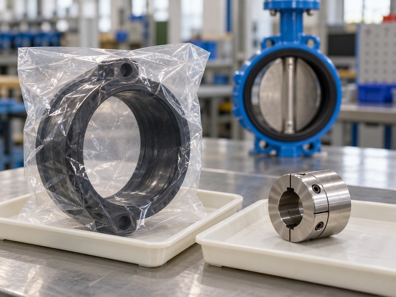
An enquiry about a resilient seated concentric butterfly valve should identify whether the concern involves internal geometry, the pipe interface or the drive. These questions help direct the review to the appropriate drawing and inspection evidence.
Q1. Can I establish the shaft offset from an outside photograph?
Not reliably. Use the section drawing to confirm internal geometry. External symmetry and the position of the operator do not establish the dimensions of the sealing arrangement.
Q2. How do I know if my flange bore is large enough?
Compare its minimum clear bore and nearby restrictions with the complete disc envelope. Check both sides and include any lining or reducer that limits the opening space.
Q3. Can I add a gasket to improve a leaking installation?
Follow the valve-specific instructions. An added gasket may alter liner compression. Establish the cause of leakage and confirm the approved interface before changing the assembly.
Q4. Does a larger actuator solve difficult operation?
Only if the original selection is inadequate and the revised assembly remains within the valve’s limits. Investigate interference, seat condition and drive alignment under safe isolated conditions.
Q5. What’s the best information to retain after repair?
Keep the unit identification, changed parts and revisions, approved repair procedure and repeated inspection results. These records connect the repaired assembly with the configuration accepted for service.