
Choose between single acting and double acting butterfly valve options by defining the required response to air loss, checking torque across the stroke, and reviewing the complete controls. A spring-return actuator stores mechanical energy for a return movement; a standard double-acting actuator uses air for movement in both directions. Either can be unsuitable if the selected package does not meet your process duty. Begin with the failure event and required valve position, then select and verify the hardware.
1. Which single acting and double acting butterfly valve fits?
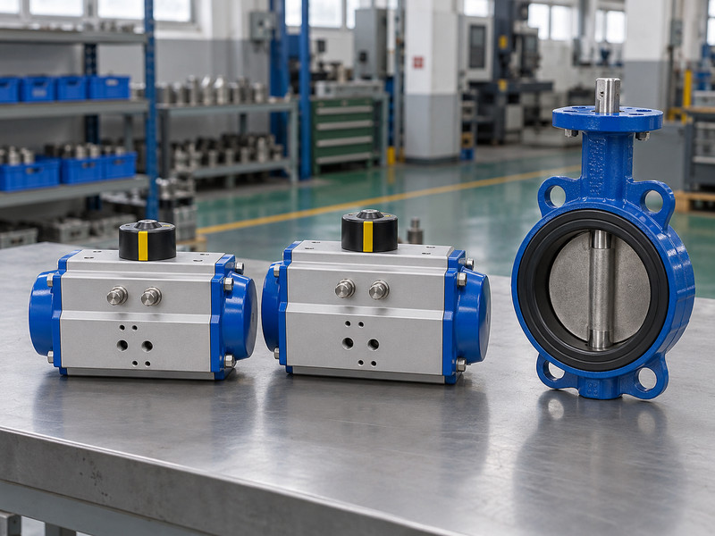
The suitable option is the one that meets the stated operating and failure requirements within its verified limits. Comparing single acting and double acting butterfly valve packages by exterior size or price alone misses those requirements. Start by separating normal control, loss-of-power behaviour, loss-of-air behaviour, and restoration of the supplies.
What should the process team decide before selection?
State what the valve must do after each specified failure and what movement time is acceptable. Closing may be appropriate for one process while opening or another defined state is required for another. Confirm whether the requirement includes maintaining that state and under what loads. Once those decisions are recorded, the supplier can review actuator output, stored energy where applicable, control arrangement, and the test conditions needed to demonstrate the response.
- Define normal operating duty and abnormal events separately.
- State required position, response time, and maintaining conditions.
- Identify the project team responsible for accepting the response.
| Selection input | Question | Consequence |
|---|---|---|
| Process requirement | What state is required after failure? | Determines the intended response |
| Available energy | What remains after that event? | Constrains the actuation arrangement |
| Verification | How will the response be demonstrated? | Defines the acceptance test |
Key takeaway: Select the actuator after the process requirement has a clear, testable description.
2. How does a spring-return actuator operate?
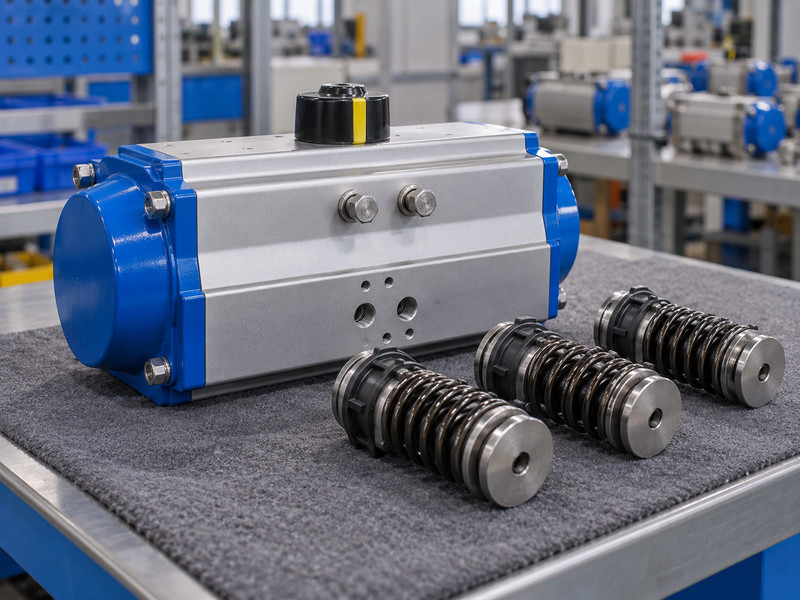
A spring-return actuator uses pneumatic energy for one movement and stored spring energy for the return movement. In single acting and double acting butterfly valve comparisons, this is the main operating distinction for the common spring-return arrangement. The installed design can be configured for the intended opening or closing return action.
What should you verify about the return stroke?
Return torque can vary through the stroke, so one maximum figure cannot establish performance at every position. Review the spring configuration, valve torque, temperature, process differential pressure, and relevant mechanical limits. The normal air-driven stroke also needs enough output after accounting for spring opposition. During maintenance, follow the specific instructions for stored spring energy; removing the air supply does not make internal disassembly safe by itself.
- Confirm the specified spring-return action and configuration.
- Review both the air stroke and spring stroke.
- Retain the manufacturer’s stored-energy service instructions.
| Operating part | Energy source | Required check |
|---|---|---|
| Air stroke | Compressed air | Available output throughout travel |
| Return stroke | Springs | Return output against valve demand |
| Internal service | Potential stored mechanical energy | Approved isolation and disassembly method |
Key takeaway: A spring-return label describes the mechanism; the selected spring and valve combination still needs verification.
3. How does double-acting operation differ?
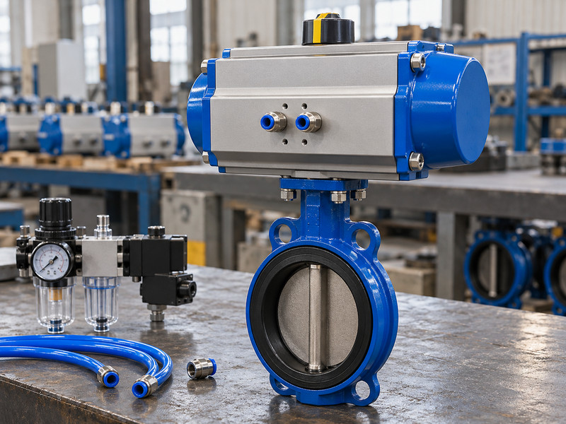
Double-acting operation uses compressed air to drive movement in both directions. When reviewing single acting and double acting butterfly valve packages, check both working pneumatic circuits and their controls. A standard double-acting actuator has no inherent spring-powered return stroke after the air supply disappears.
What should you check about position after air loss?
Trapped air, internal leakage, control-valve behaviour, and process torque can affect the eventual valve position. If a maintained or return position is required, review the engineered arrangement that provides it and the conditions it covers. Stored-air solutions, where selected, need their own capacity and leakage assessment. The package must also meet opening and closing torque requirements at the specified minimum air pressure, with maximum output checked against the drive’s allowable loads.
- Define both working air paths and their control states.
- Verify output for opening and closing.
- Obtain an engineering basis for any required air-loss response.
| Requirement | Standard double-acting characteristic | Additional review |
|---|---|---|
| Opening and closing | Both use pneumatic energy | Minimum dynamic air supply |
| Air-loss return | No inherent spring return | Engineered response arrangement |
| Maintained position | Depends on the complete system | Load, leakage, duration, and verification |
Key takeaway: Treat a promised air-loss state as a system requirement that needs a documented mechanism and test.
4. Are power loss and air loss the same test?
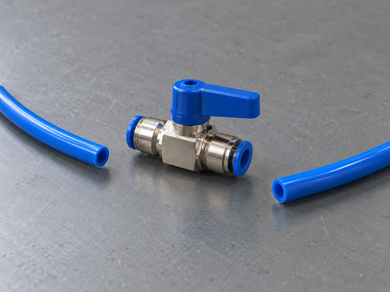
No. Electrical power loss and pneumatic supply loss remove different energy sources. A single acting and double acting butterfly valve evaluation must consider each event separately. A solenoid may change air routing after power loss while the actuator still has usable supply air; that condition does not represent loss of the air supply.
Which failure cases belong in the test plan?
Define power loss with air available, air loss under the selected control state, any working-line failure included by the project, and restoration of the supplies. State the permitted final position and response time for each. Test the accepted arrangement using the relevant procedure and representative loads. A successful demonstration of one event should not be extended to events that leave different air paths, loads, or available energy.
- Identify which supply is removed in each test.
- State the initial valve and control conditions.
- Include the agreed restart sequence after supply restoration.
| Event | What changes | Acceptance question |
|---|---|---|
| Power loss | Electrical command or coil state | How does the pneumatic circuit respond? |
| Air loss | Available pneumatic energy | What drives or restrains the valve? |
| Restoration | Energy becomes available again | Under what conditions may movement resume? |
Key takeaway: Keep failure-event test records separate so their results remain interpretable.
5. How should you compare actuator torque?
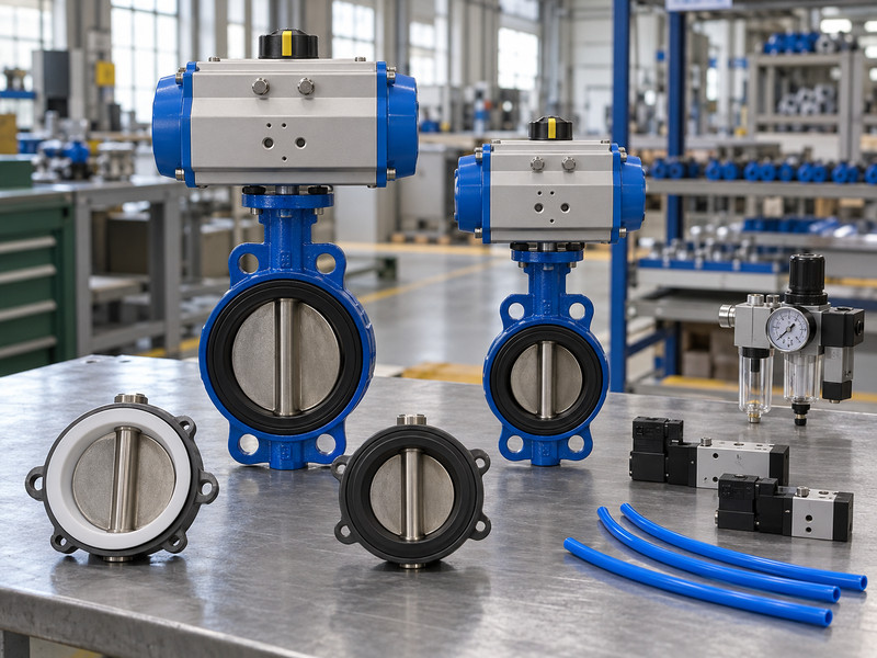
Compare usable output against valve demand across the required stroke and operating cases. A single acting and double acting butterfly valve comparison should use the actual selected actuator data rather than a general claim that one type always produces more useful torque. Package size alone does not establish the result; where ISO 5211 attachments are specified, check the contracted edition and actual drive interfaces.
Which curves and limits should remain visible?
For spring return, check the available air-stroke and spring-stroke output at the applicable positions. For double acting, review both movement directions at minimum dynamic air pressure. Use configuration-specific valve torque and the project’s documented sizing method. Then check maximum possible output against shaft, coupling, bracket, and other drive limits.
- Compare the required torque at relevant travel positions.
- State minimum dynamic air pressure and sizing allowances.
- Review maximum output against the complete drive path.
- A package with enough starting output can still fail near the end of a stroke, while an oversized drive can exceed a component’s allowable load.
| Package | Output information to review | Separate limit check |
|---|---|---|
| Spring return | Air and spring curves | Valve and mounting component strength |
| Double acting | Opening and closing output | Maximum supplied-air output |
| Either type | Actual valve torque basis | Configuration and service suitability |
Key takeaway: Compare the selected assemblies under the same duty rather than ranking actuator principles by one catalogue number.
6. Which option consumes less compressed air?
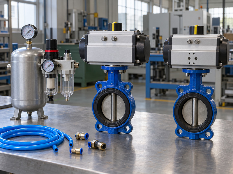
Air consumption depends on the selected actuator size, supply pressure, operating sequence, and leakage. Single acting and double acting butterfly valve options should be compared using model-specific consumption data for the same valve duty. A general operating principle does not establish the annual air cost of two differently sized packages.
How do you make a useful operating-cost comparison?
Use the relevant consumption definition from each manufacturer and the site’s expected cycle rate. Include partial movements or modulation where applicable and check any accessories that use air continuously. Record whether quoted quantities refer to supply conditions or a stated normalized reference. Then use a consistent site cost basis.
- Use the selected models and a common duty cycle.
- Keep pressure and reference conditions consistent.
- Include the actual operating frequency and relevant leakage assumptions.
- A spring-return actuator may require a different size to meet the same valve torque, so comparing equal exterior sizes can produce a misleading purchasing result.
| Cost input | Required consistency | Source |
|---|---|---|
| Air per cycle | Same definition and reference basis | Model-specific manufacturer data |
| Operating pattern | Same completed duty | Process or equipment specification |
| Air cost | Same site accounting basis | Plant utility information |
Key takeaway: Calculate the comparison from selected hardware and actual duty before making an energy-cost claim.
7. How do the control accessories differ?
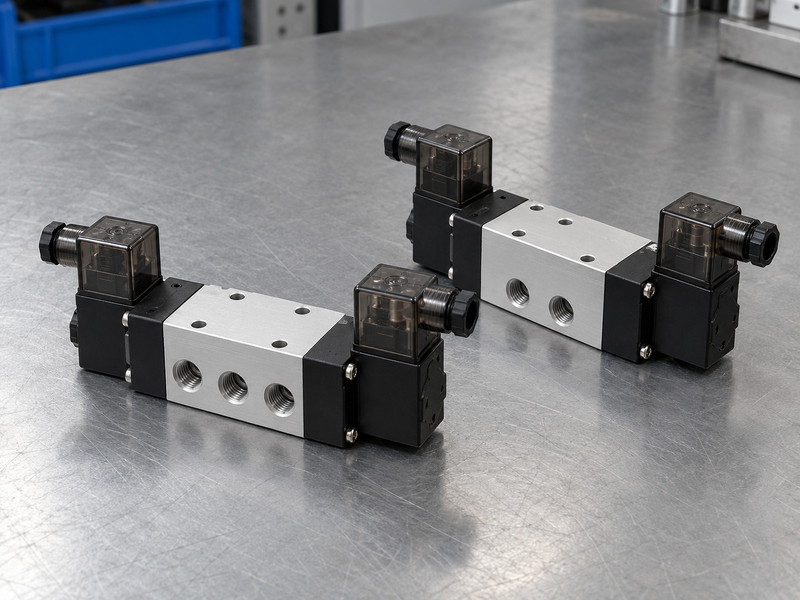
The control circuit must suit the selected actuator’s working air paths and required behaviour. A single acting and double acting butterfly valve comparison should include directional valves, feedback, air preparation, and any positioner or override. The actuator price alone does not describe the complete control package.
What should you ask about the proposed circuit?
Common on/off arrangements use suitable three-port control for a spring-return actuator and suitable five-port directional control for a double-acting actuator, but the actual design must be verified. Confirm voltage, flow capacity, exhaust arrangement, rest state, and environmental requirements. For modulation, review the positioner’s compatibility and control function separately. Keep local overrides and signal restoration in the sequence so the operator and controller do not assume different states after maintenance.
- Confirm pneumatic function for the actual actuator.
- Review electrical supply and feedback compatibility.
- Define local override, de-energized state, and restoration.
| Accessory review | Common requirement | Configuration-dependent point |
|---|---|---|
| Directional control | Suitable supply and exhaust paths | Actuator type and required rest state |
| Position feedback | Correct signal and mechanical relationship | Controller and enclosure requirements |
| Air preparation | Specified air condition and capacity | Site supply and operating duty |
Key takeaway: Compare complete control functions so an apparently lower price does not omit required behaviour.
8. What changes in maintenance planning?
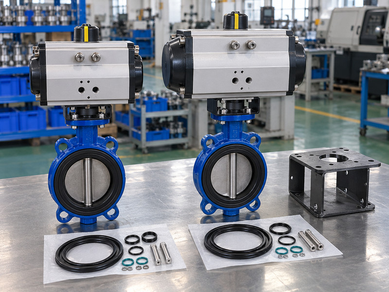
Maintenance planning must address the stored energy, service instructions, spare parts, and isolation method of the selected assembly. Single acting and double acting butterfly valve packages share some inspection needs but can require different internal service procedures. Do not transfer a dismantling method from one operating principle to another.
Which records help a maintenance team choose correctly?
Keep the actuator model and configuration, valve materials, coupling and bracket details, accessory identification, accepted settings, and replacement-part information. Spring configuration is relevant where springs are fitted. Process isolation, pneumatic isolation, electrical isolation, and any stored energy must be addressed under the applicable site procedure. For a flanged butterfly valve, include the approved connection and support details so removing a drive or valve does not rely on an assumed pipe arrangement.
- Use the instructions for the exact installed assembly.
- Identify all applicable energy and isolation points.
- Review replacements against torque, function, and mounting requirements.
| Maintenance information | Supports | Review after |
|---|---|---|
| Actuator configuration | Correct service procedure | Drive replacement or internal change |
| Settings and tests | Restoration of accepted function | Adjustment or repair |
| Spare-part details | Correct materials and fit | Approved component substitution |
Key takeaway: Make maintenance information part of the purchase package before the equipment needs its first repair.
9. How do you approve the final comparison?
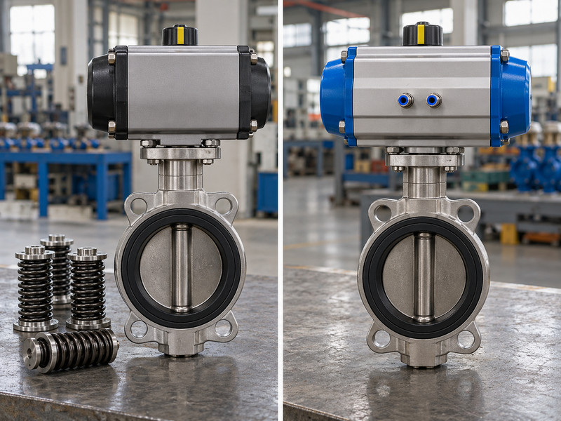
Approve the option that meets the defined process, operating, failure, and maintenance requirements with acceptable evidence. A single acting and double acting butterfly valve comparison is complete when the chosen assembly and its acceptance plan are defined. A preferred operating principle still needs a configuration-specific review.
What should the decision record contain?
Compare the required failure response, usable torque, air conditions, controls, installed space, documents, and operating costs on a common basis. List unresolved inputs and avoid assigning a final approval where a governing condition remains unknown. Freeze the selected valve and actuator configuration, then identify changes that require reassessment. This helps a later buyer understand why a lower-cost substitute may be acceptable, or why it would change the response the process team required.
- Compare assemblies against the same service data sheet.
- Close governing technical inputs before procurement release.
- Retain the selected configuration and its verification basis.
| Decision area | Accept when | Hold when |
|---|---|---|
| Function | Required response is defined and supported | Failure behaviour remains assumed |
| Mechanics | Output and component limits are checked | Torque basis or interface is missing |
| Operation | Utilities, controls, and maintenance suit the duty | Unresolved conditions affect performance |
Key takeaway: Send your failure events, valve duty, and air conditions when you contact us. RUITO can review the information needed to compare suitable assembly options.
10. What should buyers ask about fail action?
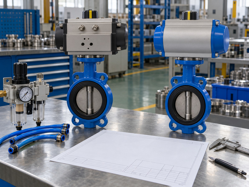
Use these questions when reviewing single acting and double acting butterfly valve quotations.
- Q1: Can I assume spring return always means fail closed? No. The package can be arranged for a specified return action. Confirm the actual configuration and verify its response against the required valve load.
- Q2: What’s the best actuator for air loss? Select an arrangement that delivers the process team’s required state under the specified event. Review the complete mechanism, controls, loads, and test evidence.
- Q3: Can double acting hold its last position indefinitely? Do not assume that. Leakage, process loads, and control paths can change position. A maintained-state requirement needs its own engineered basis and verification.
- Q4: How do I compare air costs fairly? Use the selected models, common reference conditions, the same completed duty cycle, and the site’s operating frequency and air-cost basis.
- Q5: Can I convert a double-acting actuator by adding springs? Only where the manufacturer supports the exact conversion and the complete assembly is reviewed. Recheck output, configuration, control function, mounting, and acceptance requirements.