
Fix soft seated butterfly valve selection mistakes by checking the fluid, seat compound, pressure at temperature and installation interface together. A soft seat uses a nonmetallic sealing surface, commonly an elastomer or an engineered polymer, against a rotating disc. The valve name identifies a sealing family; your approved drawing and bill of materials identify the product you can buy.
A replacement DN150 valve can match the pipe size and still fail during commissioning. The disc may catch the flange bore, an oil additive may swell the seat or the actuator may stall against closing differential pressure. Start with a service data sheet and close those three checks before comparing prices. RUITO reviews the actual material and connection configuration, rather than combining unrelated catalogue limits.
1. What types of soft seated butterfly valve can you specify?
You can specify a soft seated butterfly valve by its seat material, disc geometry, connection and drive. These choices are separate. A wafer body can have an elastomer seat or a polymer lining, while a flanged body can use a concentric or offset design. Write those four features into your enquiry instead of accepting one broad product description.
Which features belong on the data sheet?
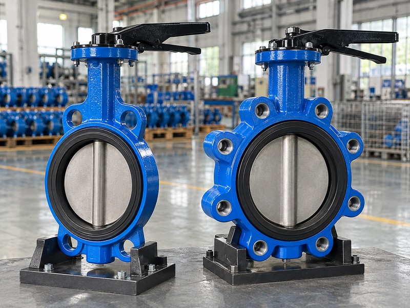
Keep disc geometry separate from seating material: an offset alone does not prove a metal seal, a fire test or a temperature rating. RUITO’s wafer and concentric double-flanged water ranges include DN50–600, while the lug range is DN50–300. Specify the actual build. Each quoted range needs its own seat, connection and approved pressure configuration.
- State the complete seat material and compound requirement.
- Identify wafer, lug, double-flanged or another approved connection.
- Name the manual, electric or pneumatic drive and required action.
Key takeaway: You can compare offers only when each supplier quotes the same geometry, seat, connection and operating function.
| Check | What you should confirm |
|---|---|
| Seat | Elastomer or polymer, with the approved compound identified |
| Geometry | Concentric or offset, supported by the section drawing |
| Connection | The actual flange interface and face-to-face length |
2. How does a soft seated butterfly valve seal?
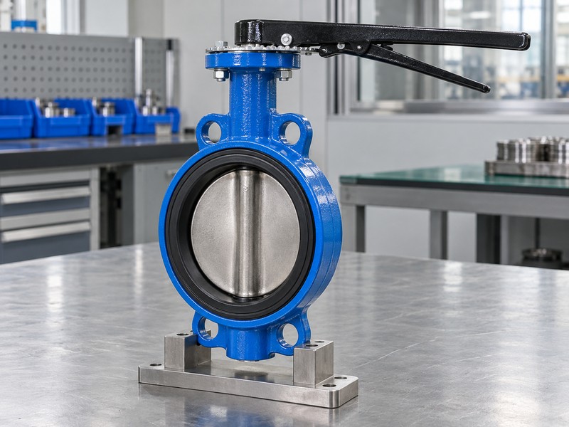
A soft seated butterfly valve seals when the disc edge develops the specified contact with its seat. In a concentric elastomer design, controlled interference compresses the seat during closure. The shaft seals also contain the fluid. A tight disc edge cannot compensate for a damaged liner, a leaking shaft interface or a wrongly indexed closing stop.
What can change the contact pressure?
Disc size, seat profile, rubber condition and body support affect sealing contact. Excess compression can raise torque, while uneven flange tightening can distort the liner and leave a leakage path. Check the whole sealing path. Inspect the edge, both shaft regions and flange contact faces before adjusting the drive or replacing components.
- Inspect the continuous seat surface for cuts or trapped debris.
- Check that the closing stop matches the actual disc position.
- Record shaft leakage separately from leakage across the closed disc.
Key takeaway: Diagnose the leakage location before changing the seat, actuator setting or flange tightening sequence.
| Check | What you should confirm |
|---|---|
| Disc edge | A continuous, undamaged contact surface around the seat |
| Shaft region | Matched seals and correctly retained shaft components |
| Travel stop | A closing position confirmed against the actual valve |
3. Which seat suits a soft seated butterfly valve?
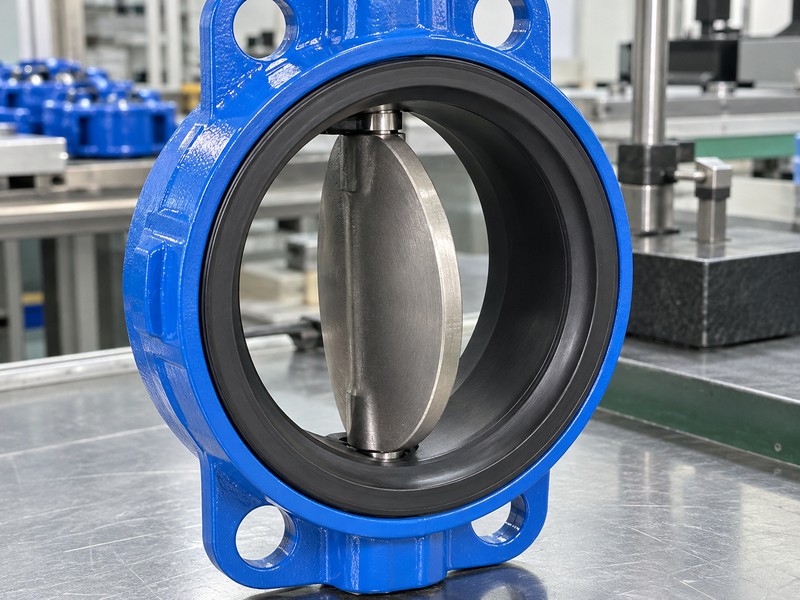
Choose the seat for a soft seated butterfly valve from the complete fluid composition and operating envelope. EPDM is a common water-service option, while NBR can suit approved mineral oils. PTFE or PFA-lined configurations address different chemical duties. Those names describe material families; the exact compound, liner construction and supporting seals still govern acceptance.
What fluid details should you provide?
Send concentration, additives, contaminants and cleaning fluids with the enquiry. RUITO’s normal cooling selections cover clean water or approved inhibited ethylene glycol up to 40% by volume, at 5–60°C and no more than 10 barg within the model rating. Name the mixture. Neat mineral oil and an acid dosing line require different material reviews.
- List every service fluid and cleaning chemical the valve contacts.
- State the concentration basis, operating temperature and exposure pattern.
- Request written acceptance for the exact seat and shaft-seal combination.
Key takeaway: Approve the complete wetted-material configuration, not a seat material selected from a colour chart.
| Check | What you should confirm |
|---|---|
| Water circuit | Review EPDM compound, glycol concentration and inhibitors |
| Mineral oil | Review the NBR compound against the actual oil formulation |
| Chemical line | Review the complete polymer lining and supporting seals |
4. What pressure can a soft seated butterfly valve handle?
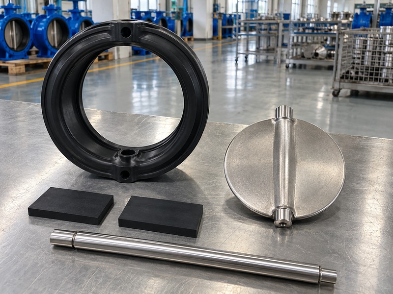
The allowed pressure for a soft seated butterfly valve is the lower applicable limit of its body, seat, connections and service qualification at temperature. PN16 does not authorize 16 barg at every temperature or in every fluid. The closed-valve differential pressure can also have a separate limit, especially when the valve serves as a pipeline end closure.
Which pressures should you keep separate?
Provide operating pressure, transient pressure and maximum closing differential pressure separately. A body pressure test establishes an inspection condition and does not raise the service rating. Keep the limits paired. RUITO’s ordinary clean-water window is 5–60°C within the model curve, with 20°C limits tied to the approved PN10 or PN16 build.
- Request the model pressure-temperature curve and its material scope.
- Declare pressure reversal, surge and the maximum closed-valve differential.
- Check the joint, flange and seat limits before approving operation.
Key takeaway: Your approval should state one compatible pressure-temperature-duty combination for the complete valve and joint.
| Check | What you should confirm |
|---|---|
| Operating pressure | The pressure permitted in the actual fluid at temperature |
| Closing differential | The approved pressure difference across the closed disc |
| Test pressure | A documented inspection condition, not a service rating |
5. Which connection fits a soft seated butterfly valve?
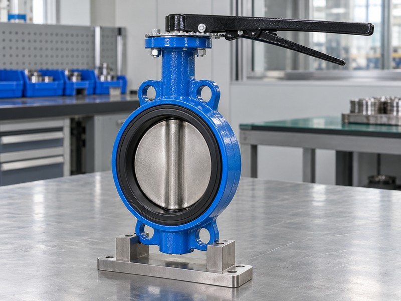
A soft seated butterfly valve connection must match the flange drilling, face-to-face space and disc opening clearance. A wafer valve normally uses through-bolts between two supporting flanges. A lug valve uses threaded body lugs with model-specific bolt engagement. Double-flanged valves have their own bolting and installation length. Equal DN values do not make these interfaces interchangeable.
How do you avoid a flange-bore clash?
Review the actual pipe bore, including lining and nearby reducers, against the disc opening envelope. Many thin wafer and lug bodies allow the disc to sweep beyond their faces. Compare the drawings. Follow the manual on extra gaskets, because additional compression can distort a liner designed to seal directly against the flange.
- Check flange standard, drilling, facing and the actual internal bore.
- Confirm the opening envelope against reducers, lining and adjacent fittings.
- Use the specified bolt length, engagement and tightening sequence.
Key takeaway: A dimensioned interface review prevents site rework more reliably than matching only DN and PN labels.
| Check | What you should confirm |
|---|---|
| Wafer | Through-bolts and two correctly aligned supporting flanges |
| Lug | Approved threads, bolt engagement and end-service rating |
| Double-flanged | Its own face-to-face drawing and flange bolt schedule |
6. How do you size a soft seated butterfly valve for flow?
Size a soft seated butterfly valve using the required flow, allowable pressure drop and the correct model flow coefficient. Nominal diameter alone does not predict performance. For single-phase liquids, density and viscosity influence the calculation. Gas duty needs its own method using absolute pressure and defined flow conditions, rather than an unchanged water calculation.
What does a flow calculation tell you?
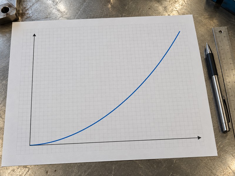
For an applicable single-phase-liquid calculation, Kv relates flow to pressure difference and relative density. A worked water estimate at 100 m³/h with Kv 300 gives about 0.111 bar pressure drop; this is not a guaranteed RUITO curve. Use the actual coefficient. Obtain the approved value at the selected opening and check the system pressure budget.
- Provide minimum, normal and maximum required flow rates.
- Use the approved coefficient for the actual valve size and opening.
- Check the complete system budget and any throttling restrictions.
Key takeaway: Keep a worked sizing estimate separate from the manufacturer’s guaranteed performance for the supplied configuration.
| Check | What you should confirm |
|---|---|
| Liquid flow | Apply the actual density and suitable viscosity treatment |
| Pressure drop | Use the coefficient at the selected operating position |
| Gas service | Use absolute pressure and the approved gas sizing method |
7. Which actuator suits a soft seated butterfly valve?
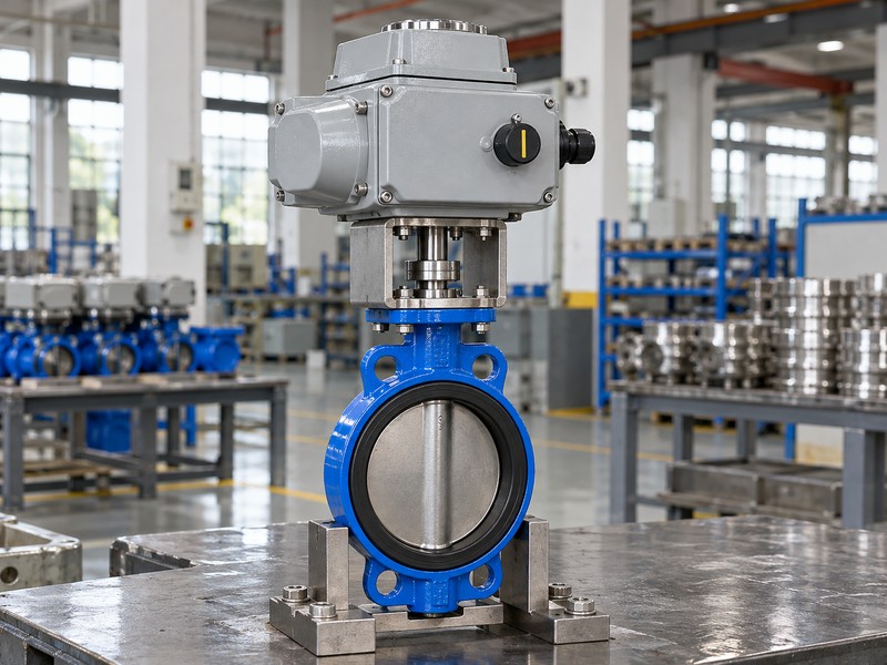
Select the drive for a soft seated butterfly valve against the maximum required valve torque and minimum available supply. Account for breakaway, running and seating torque. An actuator’s peak brochure output may not be available through its entire stroke. The mounting interface, coupling and shaft strength must also support the selected load.
What can cause an actuator to stall?
Temperature, pressure difference, seat interference and contamination can alter torque demand. Pneumatic sizing uses minimum available air pressure, including the required spring-return stroke; electric sizing uses the specified supply and operating duty. Check both directions. Record the margin, mounting arrangement, feedback and fail action in the assembly calculation.
- Use model torque values for the actual fluid and closing pressure.
- Calculate output at minimum air pressure or the specified electrical supply.
- Verify fail position, travel stops, feedback and mounting geometry.
Key takeaway: Accept the valve and actuator as a checked assembly, with an identified torque calculation and supply condition.
| Check | What you should confirm |
|---|---|
| Valve demand | Breakaway, running and seating torque at the stated duty |
| Drive output | Available output throughout travel at minimum supply |
| Assembly | Approved coupling, bracket, shaft load and feedback position |
8. How should you install a soft seated butterfly valve?
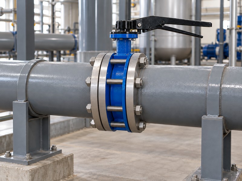
Install a soft seated butterfly valve between aligned, supported pipe ends using the approved procedure. Keep the disc position suitable for insertion and flange tightening, then confirm unobstructed travel before commissioning. Remove welding debris and protect the seat during installation. The valve body should not carry an unreviewed pipe bending load or correct a misaligned joint.
What should the installer verify on site?
Check the valve against the approved drawing and service sheet before insertion. Follow the manual’s tightening sequence and instructions for gaskets, lubrication and mating surfaces. Check before pressurizing. Confirm unobstructed disc movement and correctly indexed indication with the line safely prepared, then complete the project commissioning checks.
- Clean the mating surfaces and remove debris from the flow path.
- Support both pipe ends and tighten the joint in the approved sequence.
- Confirm free disc travel and truthful open-and-closed feedback.
Key takeaway: Commissioning begins with a clean, aligned joint and verified disc movement, before pressure exposes an installation fault.
| Check | What you should confirm |
|---|---|
| Pipe support | External supports maintain alignment and control bending loads |
| Joint assembly | Correct gaskets, fasteners and tightening procedure |
| Travel check | No disc contact with the pipe bore or adjacent fittings |
9. Which tests verify a soft seated butterfly valve?
Verify a soft seated butterfly valve with the pressure, closure, external-leakage and function tests specified for its configuration. A water test alone does not approve every gas service. Polymer-lined valves also need their defined liner inspections. Agree the governing method, direction, test conditions and acceptance criterion before the supplier starts the inspection programme.
Which evidence should accompany the result?
An applicable method such as ISO 5208 accompanies the product’s stated inspection requirements. Reports identify the valve, medium, pressure, duration, direction and calibrated instruments. Match the report to the valve. RUITO clean-gas configurations add their specified gas-tightness checks after hydraulic inspection, with delivered product IDs linked to the results.
- Agree the governing test method and any product-specific additions.
- Keep shell integrity, seat leakage and external leakage as separate results.
- Require product IDs, directions, test conditions and instrument records.
Key takeaway: Accept traceable results for the supplied configuration, rather than a generic certificate describing a valve family.
| Check | What you should confirm |
|---|---|
| Pressure boundary | The applicable shell and external-leakage inspection |
| Closure | The agreed seat-leakage criterion and pressure direction |
| Special duty | Additional gas, liner or temperature validation as required |
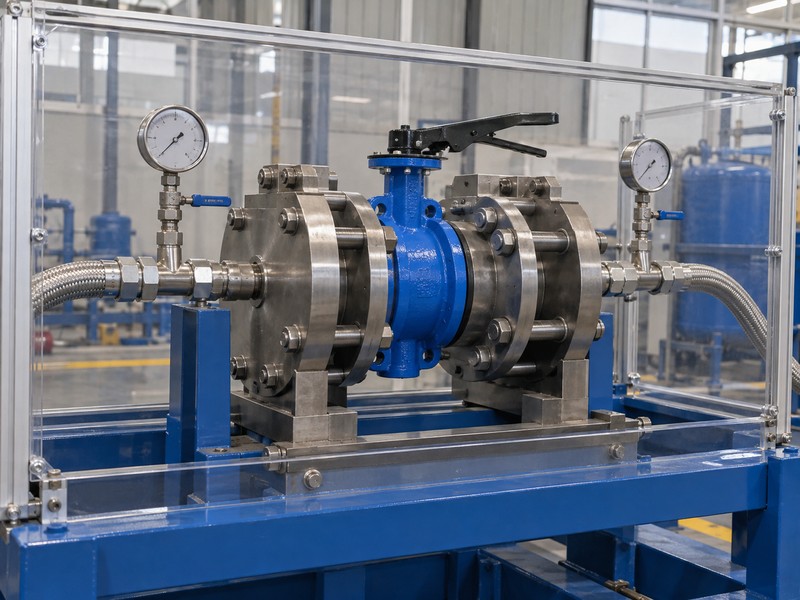
10. What records support a soft seated butterfly valve order?
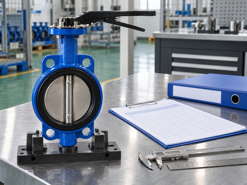
A soft seated butterfly valve order needs a controlled data sheet, drawing, material list, test plan and maintenance information. Record accepted deviations before manufacture. The same identification should connect the valve, inspection results, spare parts and packing list. That link lets you approve repeat supply without silently changing a seat compound, flange interface or actuator setting.
How do you protect repeat orders?
Retain the approved revision with the order and require notice before changing a critical material or dimension. Spare-part identification and inspection results should describe that same configuration. Freeze the approved version. RUITO can review the drawing, material scope and inspection requirements against the service inputs; purchasing retains the acceptance and replacement-part records.
- Freeze the approved drawing, material configuration and accepted deviations.
- Connect product IDs with test reports, packing and spare-part references.
- Define how substitutions and drawing revisions require written approval.
Key takeaway: A controlled order record gives maintenance and purchasing teams the same definition of the valve they must replace.
| Check | What you should confirm |
|---|---|
| Purchase record | The exact approved configuration and service conditions |
| Shipment record | Product identification linked to inspection and packing |
| Maintenance record | Correct spare parts and the current installation manual |
Send RUITO your fluid composition, operating and transient pressures, temperatures, flange drawing and drive requirements. We can review the configuration, identify unresolved technical inputs and prepare the matching quotation and document scope. Contact us with that package before you approve a replacement. RUITO quotes the defined duty and accepted configuration.
FAQ
Q1: Can I use an EPDM seat for mineral oil?
Do not assume it is suitable. Review an approved oil-service compound, such as the specified NBR configuration, against the actual oil and additives.
Q2: How do I know if a PN16 valve suits my temperature?
Check its model pressure-temperature curve. The permitted duty also depends on the seat, joint and fluid qualification.
Q3: Can I use a lug valve as an end closure?
Only with a declared end-service rating. The exact size, threads, bolts, differential pressure and test scope must match that use.
Q4: What’s the best evidence of tight shutoff?
A traceable closure-test report is the relevant evidence. It should identify the valve, direction, pressure, test method and acceptance criterion.
Q5: Can I size the actuator from pipe diameter?
No. Use the valve torque demand at the actual duty and the actuator output at minimum available supply.